Table of Contents
Advertisement
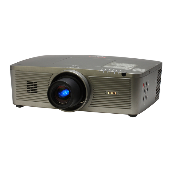
SERVICE MANUAL
LC-WUL100L
* Projection lens is optional.
For your convenience, all service parts, identified in this manual are available through Eiki's normal distribution chan-
nels.
In addition to service part number, the generic descriptions have been given, where possible, to allow your service
technicians to substitute equivalent components which might be available from other sources.
All orders for service parts will be honored. However, in instances where generic components are considered to be
available from several common sources, as would be the case with an industry standard fuse, resistor, or semicon-
ductor, it may be more economical and expeditious to purchase the part locally.
LC-WUL100
LC-WUL100L
1 122 555 01
1 122 555 21
(KH2B)
1 122 556 01
1 122 556 21
(LH2B)
1 122 556 06
1 122 556 26
(LH2G)
Multimedia Projector
FOREWORD
(KH2BL)
(LH2BL)
(LH2GL)
Model No. LC-WUL100
LC-WUL100L
U.S.A., Canada,
Europe, H.K
OrigiNaL VersiON
Chassis No. KH2-WUL10000
KH2-WUL100L00
Give complete "Chassis No." for parts
order or servicing, it is shown on the
rating sheet on the cabinet on the pro-
jector.
SM
SM
REFERENCE NO.
REFERENCE NO.
5111291-00
5111174-00
Advertisement
Table of Contents

Related Manuals for Eiki LC-WUL100


Summary of Contents for Eiki LC-WUL100
-
Page 1: Service Manual
* Projection lens is optional. FOREWORD For your convenience, all service parts, identified in this manual are available through Eiki’s normal distribution chan- nels. In addition to service part number, the generic descriptions have been given, where possible, to allow your service technicians to substitute equivalent components which might be available from other sources. -
Page 2: Table Of Contents
Contents SERVICE MANUAL ........... 1 Indicators and Projector Condition ......78 Contents ................ 2 Power failure detection system ........ 81 Safety Instructions ............3 Diagnosis of Power Failure with RS-232C port ..85 Safety Precautions ............. 3 Serial Control Interface ..........86 Product Safety Notice .......... -
Page 3: Safety Instructions
Safety Instructions Safety Precautions WARNING: The chassis of this projector is isolated (COLD) from AC line by using the converter transformer. Primary side of the converter and lamp power supply unit circuit is connected to the AC line and it is hot, which hot circuit is identified with the line ( ) in the schematic diagram. -
Page 4: Specifications
Dimensions (W x H x D) LC-WUL100L : 19.27'' x 6.46'' x 14.61'' (489.5 mm x 164.0 mm x 371.1 mm) LC-WUL100 : 19.27'' x 6.46'' x 17.12'' (489.5 mm x 164.0 mm x 434.8 mm) Net Weight LC-WUL100L : 19.8 lbs (9.0 kg) LC-WUL100 : 21.6 lbs (9.8 kg) -
Page 5: Circuit Protections
Circuit Protections This projector provides the following circuit protections to operate in safety. If the abnormality occurs inside the pro- jector, it will automatically turn off by operating one of the following protection circuits. Fuse A fuse is located inside of the projector. When the POWER indicator is not lighting, the fuse may be opened. -
Page 6: Mechanical Sensor Switches (Sw901, Sw1891)
Circuit Protections Mechanical sensor switches (SW901, SW1891) LeD indicators This projector provides 2 mechanical sensor switches, the one is for filter car- tridge switch (SW1891) and the other one is for lamp cover switch (SW901). The filter cartridge switch detects whether the filter cartridge is installed cor- rectly. -
Page 7: Temperature Sensors, Wind Sensors
Circuit Protections Temperature sensors, wind sensors The projector provides 2 temperature sensor ICs, 1 thermistor, and 1 wind sensor on the intake duct. These devices are monitoring the surrounding temperature of the lamp, panel and intake duct, and the wind sensor is monitoring airflow passed through the air filter in the intake duct. -
Page 8: Power Failure And Fan Lock Detection
Circuit Protections Power failure and fan lock detection The projector provides the detection circuits of the power failure and the fan lock. When the detection circuit detects an error at the power supply line or at the fan operation circuit, the projector will turn into the standby mode to protect the other circuits defective. -
Page 9: Maintenance
Maintenance Replacing the Filter Cartridge Filter prevents dust from accumulating on the optical elements inside the projector. Should the filter becomes clogged with dust particles, it will reduce cooling fans’ effectiveness and may result in internal heat buildup and adversely af- fect the life of the projector. -
Page 10: Resetting The Filter Counter
Maintenance Resetting the Filter Counter Be sure to reset the Filter counter after replacing the filter car- Filter counter tridge. Press the MENU button to display the On-Screen Menu. Use the Point ed buttons to select setting and then press the Point 8 or the SELECT button Use the Point ed buttons to select Filter counter and then press the SELECT button. -
Page 11: Lamp Replacement
CaUTiON Allow a projector to cool for at least 45 minutes before you open the Lamp cover. The inside of the projector can become very hot. New Lamp OrDer rePLaCeMeNT LaMP Model LC-WUL100, LC-WUL100L Type No. POa-LMP136 service Parts No. 610 346 9607 -11-... -
Page 12: How To Check Lamp Used Time
Maintenance How to check Lamp Used Time The LAMP REPLACE indicator will light yellow when the total lamp used time (Corresponding value) reaches 3,000 hours. This is to indicate that lamp replacement is required. The total lamp used time is calculated by using the below expression, Total lamp used time (Corresponding value) = eco + normal x 1.5... -
Page 13: Quick Maintenance
Maintenance Quick maintenance This projector provides a cabinet prism cover on the cabinet top to enhance the service maintenance. This enables service personnel to align the optical adjustment or replace the optical parts without disassembly the cabinet top. Loosen a screw-A on the lamp cover and slide it to open (Fig. -
Page 14: Lens Installation
Maintenance Lens Installation When replacing the lens or using an optional lens, install the lens by following the instructions below. removing the lens Shift the lens to the center position by using the Lens Release button Lens shift function. Turn off the projector and unplug the AC power cord. -
Page 15: Using The Lens Antitheft Screw
Maintenance Using the Lens Antitheft screw This projector provides a Lens antitheft screw to protect the projection lens stolen from a suspicious person. Mount the Lens antitheft screw by following the instructions below. Mounting the Lens antitheft screw Loosen a screw-A on the lamp cover and slide it to Lamp cover open (Fig. -
Page 16: Cleaning
Maintenance Cleaning After long periods of use, dust and other particles will accumulate on the LCD panel, prism, mirror, polarized glass, lens, etc., causing the picture to darken or color to blur. If this occurs, clean the inside of optical unit. Remove dust and other particles using air spray. -
Page 17: Security Function Notice
Security Function Notice This projector provides security functions such as "Key lock", "PIN code lock" and "Logo PIN code lock". When the projector has set these security function on, you are required to enter correct PIN code to use the projector. If you do not know the correct PIN code to the projector, the projector can no longer be operated or started. -
Page 18: Mechanical Disassembly
Mechanical Disassembly Mechanical disassembly flow chart Mechanical disassembly should be made by following procedures chart. Screws Expression Following steps show the basic procedures, therefore unnecessary step may (Type ) mm Diameter x Length be ignored. T type M Type Caution: The parts and screws, and the wiring method of the leads and ferrite cores should be placed exactly the same position as the original otherwise it may cause loss of performance and product safety. -
Page 19: Cabinet Top Removal
Mechanical Disassembly Mechanical disassembly 1. Lamp cover and Prism cover removal 1. Loosen 1 screw-A and remove the Lamp cover upward off. 2. Loosen 1 screw-B and remove the Prism cover by sliding it in the arrow direction. Lamp cover Prism cover 1-1. - Page 20 Mechanical Disassembly 2. Fan (FN905) and Main board removal 1. Remove 1 screw-A (M3x8) and 3 screws-B (T3x8) to take the Fan (FN905) upward off. 2. Remove 12 sccrews-C(M3x8) to take the Main board shield top off. 3. Remove 2 screws-D(M3x8), 8 hex-screws-E and 3 screws-F(M3x8) and then remove the main board.
- Page 21 Mechanical Disassembly 4. Shutter, Net Joint and Sensor C board removal 1. Loosen 1 screw-A and pull the shutter assy upward. 2. Remove 1 screw-B (T3x6) to take the Sensor C board off. 3. Remove 1 screw-C (T3x8) to take the Lamp Cover Switch (SW901) off. 4.
-
Page 22: Projection Lens Removal
Mechanical Disassembly 6. Projection Lens removal 1. Press and hold the Lens release button and turn the Projection Lens coun- terclockwise until it stops and put it out slowly. Projection lens Lens release button 7. Optical Unit removal 1. Remove 2 screws-A (T3x8) to take the Lens Cover Top upward off. 2. - Page 23 Mechanical Disassembly 7-1. Lens Shift assy and Iris assy removel 1. Remove 4 screws-A (M3x8) to take the Lens Shift assy off. 2. Remove 4 screws-B (M3x14) to take the Lens Mount off. 3. Remove 3 screws-C (T3x8) to take the Iris assy. Lens mount Lens shift assy Iris assy...
- Page 24 Mechanical Disassembly 8-1. Power Box disassembly and Fan (FN901) removal 1. Remove 1 screw-A (M4x8) and 3 screws-B(M3x8) and remove the Ballast shield top. 2. Remove 2 screws-C (M3x8) to take the Holder. Unhook the 4 hooks-D and take the Ballast board off. 3.
- Page 25 Mechanical Disassembly 10. Filter Assy removal 1. Remove the Filter Cover by pulling it outside. 2. Remove 4 screws-A (T3x8) and 1 screw-B (M3x8) and pull the Filter Box assy upward off. Filter cover Filter box assy T3x8 T3x8 T3x8 (T3x8)x2 Filter sensor...
- Page 26 Mechanical Disassembly 12. Fans (FN906, FN907, FN911) and Speaker removal 1. Remove 3 screws-A (T3x12) and remove fans(FN906, FN907 and FN911). 2. Remove 2 screw-B (T3x8) to take the Lens Cover Bottom upward. 3. Remove 2 screws-C (T3x8) to take the Speaker box off. Remove 2 screws- D to remove the speaker.
-
Page 27: Optical Parts Disassembly
Optical Parts Disassembly Before taking these procedures, remove the cabinet top, Main board assy, shutter assy referring to the chapter "Me- chanical Disassembly". 1. LCD Panel/Prism Assy removal 1. Open the Prism Cover. 2. Loosen 3 screws-D and pull the Panel/Prism assy upward. Panel/Prism assy * N ote on handling the LCD Panel/Prism assy LCD Panel, Polarized glasses are very sensitive parts. - Page 28 Optical Parts Disassembly 2. Polarized Glass-in removal 1. Remove 2 screws-E (M2.5x6) each on the Polarized glass assy and remove the stoppers, and pull the Polarized Glass assy upward. Polarized glass assy Point marker Polarized glass-in (R) Film attached side comes to this side Point marker Point marker...
- Page 29 Optical Parts Disassembly 3. PBS and Integrator Lens Assy removal 1. Remove 2 screws-A (M3x14) and pull the PBS and Integrator lens assy upward. M2.5x6 M2.5x6 Stopper Stopper PBS and Integrator lens assy Stopper Integrator lens-out Integrator lens-in Top view of PBs and integrator lens assy Cutting corner Rugged surface Integrator lens-out Rugged surface...
-
Page 30: Condenser Lens Assy Removal
Optical Parts Disassembly 4. Condenser Lens Assy removal 1. Remove 2 screws-A (M2.5x6) and pull the Condenser Lens Assy upward. Condenser lens Flat surface assy side M2.5x6 M2x4 Condenser M2x4 lens Stopper 5. Optical Parts in the Optical Unit removal 1. - Page 31 Optical Parts Disassembly 5-1. Mirror(B) Assy and Relay Lens(In) Assy removal 1. Remove 2 screws-A (M2.5x6) and pull the Mirror(B) assy upward off. 2. Remove 1 screw-B (M2.5x6) and 1 screw-C (M2x4), and pull the Relay lens(In) assy upward off. Relay lens(In) assy Mirror(B) assy...
- Page 32 Optical Parts Disassembly 5-2. Optical Parts in the Optical Unit When mounting or assembling the optical parts in the optical unit, the parts must be mounted in the specified location and direction as shown in the figure below. Marking behind the mirror Marking behind the mirror...
-
Page 33: Adjustments
Adjustments Adjustments after Parts Replacement ● : Adjustment necessary ❍ : Check necessary Disassembly / replaced Parts Condesner lens / LCD/ Polarized Fans relay lens Power Board Main Board Prism assy glass Wind sensor / integrator lens Optical axis adjustment ● Contrast adjustment ● ● Output voltage adjustment ● Fan voltage adjustment ●... -
Page 34: Service Adjustment Menu Operation
Adjustment Service Adjustment Menu Operation To enter the service mode To enter the “Service Mode”, press and hold the MeNU and seLeCT button for more than 3 seconds, or press and hold the MeNU button on the remote control for more than 20 seconds. The service menu appears on the screen as follows. -
Page 35: Optical Adjustment
Optical Adjustment WarNiNg : Use UV raDiaTiON eYe aND sKiN PrOTeCTiON DUriNg serViCiNg CaUTiON: To prevent suffer of UV radiation, those adjustments must be completed within 25 minutes. Before Adjustment E ach adjustment requires hex wrenches and slot screw- drivers. M ove the projection lens position to center by pressing the LENS button for more than 5 seconds. Mirror (B) adjust- When adjusting optical components adjustments, using ment Standard Zoom Lens is recommended. -
Page 36: Optical Axis Adjustment
Optical Adjustment 1. Optical axis adjustment Select the internal test pattern signal “All white” from the projector’s menu “Menu -> Setting -> Test pattern”. 1-1. Condenser lens adjustment-1 L oosen 2 screws and 1 screws M ove the condenser lens to display the color shading on the top/bottom and left/right of the screen. - Page 37 Optical Adjustment 1-2. Mirror (B) adjustment L oosen 1 screw and 1 screws M ove the Mirror-B to disappear the color band (Yellow/Magenta) on the top/bottom and left/roght of the screen. 1) Insert a slot driver into the slot and turn it to move the image vertically as shown in Fig.1-4.
- Page 38 Optical Adjustment 1-3. relay lens (r) adjustment L oosen 1 screw and 1 screw M ove the Relay lens (R) so that the color shading appeared on the top/bot- tom and left/right of the screen becomes the same width. 1) Insert a slot driver into the slot and turn it to move the image horizon- tally as shown in Fig.1-5, 2) Insert a slot driver into the slot...
- Page 39 Optical Adjustment 1-4. Condenser lens adjustment-2 M ove the condenser lens to remove the color shading on the top/bottom or left/right of the screen. 1) Insert a slot driver into the slot and turn it to move the image horizon- tally as shown in Fig.1-7. 2) Insert a slot driver into the slot and turn it to move the image vertically as shown in Fig.1-8.
-
Page 40: Contrast Adjustment
Optical Adjustment 2. Contrast adjustment Select the internal test pattern signal “All black” from the projector’s menu “Menu -> Setting -> Test pattern”. Turn the lever of polarized glass to obtain the darkest brightness and proper black color uniformity on the screen. * This adjustment should be taken in order of G-panel, R-panel and B-panel. -
Page 41: Electrical Adjustments
Electrical Adjustments Circuit Adjustments CAUTION: The each circuit has been made by the fine adjustment at factory. Do not attempt to adjust the following adjustments except requiring the readjustments in servicing otherwise it may cause loss of performance and product safety. Before taking these adjustments, turn the projector for more than 10 minutes to sta- bilize the operation. -
Page 42: Output Voltage Adjustment
Electrical Adjustment z Output Voltage adjustment 5. Select Group "260", No. "0" and set data value "0" After replacing the Power Board, perform the Output to "1". voltage adjustment as follows. The projector begins auto-calibration for SUB and then "OK" will appear on the screen. 1. - Page 43 Electrical Adjustment PC, Video, Component Manual adjustment When the PC, Video or Component Auto Calibration 4. Adjust the data values listed in the table below as the fails, take the following manual adjustment instead of 100% white parts on the screen becomes the darkest auto calibration.
-
Page 44: White Balance Adjustment
Electrical Adjustment . White Balance adjustment n Common Voltage adjustment Input mode Computer mode (Input 1 RGB) Input mode Computer mode (Input 1 RGB) Input signal 50%-RGB pattern computer signals Input signal 16-step gray scale computer signal or 16-step gray scale computer sig- 1. -
Page 45: Test Points And Locations
Electrical Adjustment Test Points and Locations MaiN BOarD TP561 TPFN2 TPFN11 TPFN3 TPFN4 K551 TP531 TPFN6 IC2301 IC301 IC401 TPFN1 TPFN5 POWer BOarD IC651 T601 VR601 VR601 T652 -45-... -
Page 46: Service Adjustment Data Table
Electrical Adjustment Service Adjustment Data Table These initial values are the reference data written from the CPU ROM to memory IC when replaced new memory IC. The adjustment items indicated with “✻” are required to readjust fol- lowing to the “Electrical adjustments”. Other items should be used with the initial data value. -
Page 47: Electrical Adjustment
Electrical Adjustment Grp / Item Function Range Initial Note Noise Region 1 <NSREGIONY1> / <NSREGIONUV1> 0 - 1023 Noise Region 2 <NSREGIONY2> / <NSREGIONUV2> 0 - 1023 Noise Gain Level <NSFILTERY**> / <NSFILTERUV**> 0 - 255 Noise Reduction (time) Noise Pixel Range <NSRANGEY>... - Page 48 Electrical Adjustment Grp / Item Function Range Initial Note 512/512/512/512/512/512 Center BB Green 0 - 1023 /512/512/512/512/512 Group 512/512/512/512/512/512 Center BB Blue 0 - 1023 Composite / S-Video / Component / Digital /D-RGB-Video /512/512/512/512/512 /AnalogRGB / RGB-Video / HDCP-PC /HDCP-AV /SCART/ PJ- Alpha Contrast 0 - 1000 60/60/60/60/60/60/ 60/60/60/60/60...
- Page 49 Electrical Adjustment Grp / Item Function Range Initial Note CXD3550_TG SHP_R 0 - 127 SHP_G 0 - 127 SHP_B 0 - 127 SCANM 0 - 3 * Common voltage FRPM 0 - 2 adjustment HST_R_PC 0 - 127 HST_G_PC 0 - 127 HST_B_PC 0 - 127 HST_R_PF...
- Page 50 Electrical Adjustment Grp / Item Function Range Initial Note WC_R_GAIN[9:8] 0 - 1023 432/432 WC_G_GAIN[9:8] 0 - 1023 432/432 WC_B_GAIN[9:8] 0 - 1023 298/298 Setting value of Group: Type L/ Type R WC_R_BRIGHT[12:8] 0 - 8191 WC_G_BRIGHT[12:8] 0 - 8191 WC_B_BRIGHT[12:8] 0 - 8191 CXD3550_VXT...
- Page 51 Electrical Adjustment Grp / Item Function Range Initial Note CXD3550_DIZ DIZ_ON 0 - 1 DIZ_EID_EN 0 - 1 DIZ_SYNCSEL 0 - 1 DIZ_FRCON 0 - 1 DIZ_MODE 0 - 3 DIZ_TEST 0 - 3 DIZ_REV 0 - 1 CXD3550_GhostFeedBack Ghost Feed Back Exe Begin Ghost Feed Back Exe 0 - 10 when Data is set to 10...
- Page 52 Electrical Adjustment Grp / Item Function Range Initial Note Lamp Control Dimmer SW 0:Auto 1:Manual 0 - 1 Lamp Power Manual Control (DIMMER_CTRL_LEVEL 0(Dark)- Manual Control 0 - 15 15(Bright)) DIMMER_CTRL_LEVEL1 Y Level1 Data for Dimmer 0 - 255 DIMMER_CTRL_LEVEL2 Y Level2 Data for Dimmer 0 - 255 DIMMER_CTRL_LEVEL3...
- Page 53 Electrical Adjustment Grp / Item Function Range Initial Note OUT_DLY_TRM Output Term 0 - 32767 15000 CMP_CHK_CNT Count of Information Sync 0 - 15 OPEN_DLY Open Output Delay 0 - 63 CLOSE_DLY Close Output Delay 0 - 63 Position Check Time Position Check Time 1 - 255 Enable Close Cmd...
- Page 54 Electrical Adjustment Grp / Item Function Range Initial Note Flow Inlet Err Threshold2 Flow Sensor Inlet Err Threshold No.2[ADC] 0 - 1023 Flow Inlet Err Threshold3 Flow Sensor Inlet Err Threshold No.3[ADC] 0 - 1023 Flow Inlet Err Threshold4 Flow Sensor Inlet Err Threshold No.4[ADC] 0 - 1023 Flow Inlet Err Threshold5 Flow Sensor Inlet Err Threshold No.5[ADC]...
- Page 55 Electrical Adjustment Grp / Item Function Range Initial Note Filter 1st Cartridge Scroll Factor 1 0 - 255 Filter 1st Cartridge Scroll Factor 2 0 - 255 Filter 1st Cartridge Scroll Factor 3 0 - 255 1st Filter Cartridge Scrolling Factor at N times Scrolling (N:1-10) Filter 1st Cartridge Scroll Factor 4 0 - 255 0: Manual Scrolling with OSD Menu...
- Page 56 Electrical Adjustment Grp / Item Function Range Initial Note Fan Temp Error Setting (Memorized) Normal Ceiling Bottom Temp A Warning (Normal) Temp A (Room) to judge the Temp Error at Normal 30-100 Temp B Warning (Normal) Temp B (Lamp) to judge the Temp Error at Normal 30-100 Temp C Warning (Normal) Temp C (Panel) to judge the Temp Error at Normal...
- Page 57 Electrical Adjustment Grp / Item Function Range Initial Note Fan1 Initial Volt 0-145 Fan2 Initial Volt 0-145 Fan3 Initial Volt 0-145 Fan4 Initial Volt Fan Start Voltage (0.1V) 0-145 Fan5 Initial Volt 0-145 Fan6 Initial Volt 0-145 Fan7 Initial Volt 0-145 Cooling Time Coolong Time Setting (x30 sec.) 1: 30 3: 90 15: 450...
- Page 58 Electrical Adjustment Grp / Item Function Range Initial Note Image AREA H WIDTH Black/White Level Area Width 0 - 4095 Image AREA V HEIGHT Black/White Level Area Height 0 - 4095 OFFSET Target Black Level Adj target 0 - 1023 OFFSET Tolerance Black Level Adj telerance 1 - 1023...
- Page 59 Electrical Adjustment Grp / Item Function Range Initial Note Composite (PAL) Composite / S-Video Disp Dots 0 - 4095 H Back Porch 0 - 4095 V Back Porch 0 - 4095 Disp Line 0 - 4095 Composite (SECAM) Composite / S-Video Disp Dots 0 - 4095 H Back Porch...
- Page 60 Electrical Adjustment Grp / Item Function Range Initial Note Total Dots 0 - 4095 1728 Disp Dots 0 - 4095 1360 H Back Porch 0 - 4095 V Back Porch 0 - 4095 Disp Line 0 - 4095 Clamp 0 - 4095 Clamp Width 0 - 4095 (SUB)H Back Porch...
- Page 61 Electrical Adjustment Grp / Item Function Range Initial Note Clamp 0 - 4095 Clamp Width 0 - 4095 (SUB)H Back Porch 0 - 4095 (SUB)V Back Porch 0 - 4095 (SUB)Clamp 0 - 4095 (SUB)Clamp Width 0 - 4095 YCbCr (1080P-60) Total Dots 0 - 4095 1100...
- Page 62 Electrical Adjustment Grp / Item Function Range Initial Note (SUB)Clamp 0 - 4095 (SUB)Clamp Width 0 - 4095 YCbCr (1080PSF-30) Total Dots 0 - 4095 2200 Disp Dots 0 - 4095 1875 H Back Porch 0 - 4095 V Back Porch 0 - 4095 Disp Line 0 - 4095...
- Page 63 Electrical Adjustment Grp / Item Function Range Initial Note Total Dots 0 - 4095 1716 Disp Dots 0 - 4095 1368 H Back Porch 0 - 4095 V Back Porch 0 - 4095 Disp Line 0 - 4095 Clamp 0 - 4095 Clamp Width 0 - 4095 (SUB)H Back Porch...
- Page 64 Electrical Adjustment Grp / Item Function Range Initial Note Disp Line 0 - 4095 1052 Clamp 0 - 4095 Clamp Width 0 - 4095 (SUB)H Back Porch 0 - 4095 (SUB)V Back Porch 0 - 4095 (SUB)Clamp 0 - 4095 (SUB)Clamp Width 0 - 4095 RGB Video (1035i)
- Page 65 Electrical Adjustment Grp / Item Function Range Initial Note (SUB)V Back Porch 0 - 4095 (SUB)Clamp 0 - 4095 (SUB)Clamp Width 0 - 4095 RGB Video (1080P - 24) Total Dots (Read only) 0 - 4095 2750 Disp Dots 0 - 4095 1874 H Back Porch 0 - 4095...
-
Page 66: Troubleshooting
Troubleshooting Chassis over view -66-... -
Page 67: No Power
Troubleshooting No Power The POWER and LAMP indicators do not light The LAMP indicator lights and LAMP REPLACE indicator is flashing If the POWER and LAMP indicators are not lighting, check the Fuse (F601) and Thermal switch (SW902) in the primary circuit If the LAMP_SWIN signal is not supplied to the Lamp Ballast, the and SB_5V of standby power supply circuit. -
Page 68: No Power (Power Supply)
Troubleshooting No Power (Power supply) SW902 THERMAL PROTECTOR F601 FUSE LF601 LOW POWERED SB_6V SB_5V STANDBY CIRCUIT Q613 Network Standby: H Eco Standby: L RL601 Q612 IC9885 POWER_SW SUB-MICOM <LC87F2G> S16V POWER CONTROL DRIVE CIRCUIT CIRCUIT IC601 IC651 S-6V PC601 CONTROL Power-on: H IC301... -
Page 69: No Power (Power Supply)
IC5842 IC5851 S2.6VPW S1.3VREF S3.3VPW PW, 2.6V, MEMORY S3.3V_V33PH S3.3VPWA D2385 Troubleshooting PF_3.3V_KS IC2391 3.3V_KS KEYSTONE, 3.3V No Power (Power supply) S3.3VAA_KS SW_3.3V_KS S3.3VAB_KS R2380 PF_1.8V_KS IC2371 1.8V_KS S1.8VSK_KS KEYSTONE, 1.8V SW_1.8V_KS S1.8VAA_KS D2381 PF_2.5V_KS IC1391 2.5V_KS KEYSTONE, 2.5V S2.5VAA_KS K31A S2.5VAB_KS SW_2.5V_KS... -
Page 70: No Power (Fan Control)
Troubleshooting No Power (Fan control) Check that the Fan voltage is correct on S16V each fan. TPFN6 Q7721 L7721 K78F FN906 (PANEL) Q7782 IC7721 FAN_ENB1 K78G Q7722 FN907 (PANEL) FAN_CONT2 K78H FN908 (PANEL) PF_FN906 Q7792 TPFN11 Q7701 L7701 K78L FN911 (PANEL) Q7783 IC7701... -
Page 71: No Power (Lamp Control)
Troubleshooting No Power (Lamp control) SW902 THERMAL PROTECTOR A901 LF601 A902 LAMP LAMP POWER LP900 BALLAST COVER SW. SW901 LAMP COVER-SW Check that the LAMP_DC_ON signal is correct. Power: High Q1861 POWER-ON:H LAMP_DC_ON POWER-ON:H IC1854 PF_FAN Q7796 IC301 LAMP_SWIN IC1853 SYSTEM INVERTER PW_MASTER_SDI... -
Page 72: Temperature Abnormality
Troubleshooting Temperature Abnormality Temperature monitor operation ● To shut down the projector urgently. The temperature monitor system is provided to prevents The CPU checks surrounding temperature of LCD damage of optical components inside a projector from panel (IC1814), Lamp (IC1816) and intake air (IC1692). overheat. Two protection systems are provided. Each If each part temperature reaches abnormal tempera- system operation as follows : ture, the CPU will turn off the projector, and will blink... -
Page 73: No Picture
Troubleshooting No Picture -73-... -
Page 74: No Sound
Troubleshooting No Sound -74-... -
Page 75: Motor Control Problems
Troubleshooting Motor control problems FOCUS FOCUS+ FOCUS+_EX IC5501 FOCUS DRIVE <BA6287> FOCUS- FOCUS-_EX IC5502 BUFFER <74LVC14> ZOOM ZOOM+ ZOOM+_EX IC5521 ZOOM DRIVE <BA6287> ZOOM- ZOOM-_EX IC6501 LENS SHIFT <TC7W53> UP/DOWN LENS_UD_PWM LENS_DOWN IC6502 UP/DOWN DRIVE <BA6920> LENS_UD_SW LENS_UP IC6551 INVERTER LENS SHIFT IC4801 <TC74ACT>... -
Page 76: Bus Control
Troubleshooting Bus control DSub15 -76-... -
Page 77: Led Drive & Rc Control
Troubleshooting LED drive & RC control -77-... -
Page 78: Indicators And Projector Condition
Troubleshooting Indicators and Projector Condition Check the indicators for the projector condition. The projector is operating normally. indicators Projector Condition WARNING WARNING LAMP POWER LAMP SHUTTER TEMP. FILTER REPLACE green blue orange orange The projector is off. (The AC power cord is unplugged.) The projector is in stand-by mode. Press the ON/ ❖... - Page 79 Troubleshooting The projector is detecting abnormal condition. indicators Projector Condition WARNING WARNING LAMP POWER LAMP SHUTTER TEMP. FILTER REPLACE green blue orange orange The temperature inside the projector is elevated close to the ❖ abnormally high level. The temperature inside the projector is abnormally high. The projector cannot be turned on.
- Page 80 Troubleshooting The projector is detecting abnormal condition. indicators Projector Condition WARNING WARNING LAMP POWER LAMP SHUTTER TEMP. FILTER REPLACE green blue orange orange If the Filter counter reached a time set in the timer setting, a Filter replacement icon (Fig.2) appears on the screen and the WARNING FILTER indicator on the top panel lights up. Replace the filter as soon as possible.
-
Page 81: Power Failure Detection System
Troubleshooting Power failure detection system Detection of Power failure Projector provides a protection circuit to prevent the secondary failure when the power failure, fans failure or tem- perature failure occurs on the projector. The power failure detection lines "PF_3.3V_AD", "PF_3.3V_KS", etc. are connected to the main power supplies. When the failure occurs, IC301<SYSTEM CONTROL> receives an error infor- mation through IC5201<FPGA>, IC4801 <I/O Expander>... -
Page 82: Power Failure Detection Tree
Troubleshooting Power failure detection tree DETECTION SUPPLIED CIRCUIT LINE NAME ERROR INFO. D5532 FILTER, PF_12V_FILTER S16V IC5532 AUDIO I/O ON_12V D592 IC3531/ PF_15.5V_GAM GAMMA, 15.5V IC3511/ IC3551 15V_SHR/G/B PANEL, S/H SH 15V_ON D5545 IC5542 S12V FILTER S3.3V D6604 LENS, PF_15V_LNS LENS SHIFT Q6612 15V_LNS... - Page 83 Troubleshooting Sensor & detection switches DETECTION LINE NAME ERROR INFO. Q2043 S-6V S-6V PF_S-6V NETWORK JOINT PF_5V_PJ PJNET, S3.3V FAN CONTROL S16V VOLTAGES FN901 FN901, PF_FN901 PF_FN902 FN902, FN902 PF_FN903 FN903, PF_FN904 FN904, FN905 PF_FN905 FN905, FN906 FN907 FN906&7&8, 13V PF_FN906 FN908 FN909...
-
Page 84: Error Log
Troubleshooting Error Log This projector provides the error history log function. To Item Data Group (Error Code) check the logs, you need to enter the service mode and <- Latest Error ✻ select Group No. "220" and Item No. "0" to "49". The error ✻... -
Page 85: Diagnosis Of Power Failure With Rs-232C Port
Troubleshooting Diagnosis of Power Failure with RS-232C port This projector provides a function to get the error information of the projector by using the RS-232C serial port for the power failure diagnosis. The further error information of the power failure and fan failure can be found out by using this function. Diagnosis procedure Connect a RS-232C serial cross cable to CONTROL PORT on the projector and serial port on the PC. -
Page 86: Serial Control Interface
Troubleshooting Serial Control Interface This projector provides a function to control and monitor the projector's operations by using the RS-232C serial port. Operation Connect a RS-232C serial cross cable to CONTROL PORT on the projector and serial port on the PC. Launch a communication software "Hyper terminal"... - Page 87 Troubleshooting status read Command Format The command is sent from PC to the projector with the format below; 'CR' [Command] 'CR' Command: one character (refer to the command table below. The projector decodes the command and returns the 'Character string' with the format below; Projector Command Function...
-
Page 88: Control Port Functions
Control Port Functions System Control I/O Port Functions (PW392, IC301) PORT SIGNAL FUNCTION NOTE HSOUT Horiz. Sync Signal Input LENS_L_POSI_EX Lens Shift Position L Detection Input PW_SDA3 IIC Bus SDA3 KEY11 Key Control Input 11 KEY31 Key Control Input 31 KEY03 Key Control Input 03 IN0HS... - Page 89 Control Port Functions PORT SIGNAL FUNCTION NOTE CB_IN_PW CB Signal Input CR_IN_PW CR Signal Input HS2_PW Horiz. Sync Signal Input 2 ON_5V ON_5V Drive Signal Output VS2_PW Vert. Sync Signal Input 2 AG10 FILTER_COUNT Filter Scroll Count Input AG11 PW_R/C_FRONT RC Input Front AG12 EX_PW_UART...
- Page 90 Control Port Functions FPGA (XC3S50A, IC5201) PORT SIGNAL FUNCTION NOTE PW_SCL0 IIC Bus SCL0 PW_SDA0 IIC Bus SDA0 CG_HSYNC Horiz. Sync Signal Input PF_S3.3V Power Failure Detection Input S3.3V PF_3.3V_AD Power Failure Detection Input 3.3V AD SW_PF3.3V PF_3.3V Switch CG_VSYNC Vert.
-
Page 91: Ic Block Diagrams
IC Block Diagrams ● FA5502 <P.F. Control, IC601> ● LV49152V<Audio Output, IC001> -91-... - Page 92 IC Block Diagrams ● BA6287 <Motor Drive Focus, Zoom, Shutter IC5501, IC5521> ● BA6920 <Motor Drive Lens Shift Up/Down, Left/Right, IC6502, IC6521> -92-...
- Page 93 IC Block Diagrams ● BA7078 <Sync Separator, IC1011> ● CXA7010 <S&H, IC1501, IC501, IC2501> ADJ DAC ADJ DAC -93-...
- Page 94 IC Block Diagrams ● ISL51002 <A/D Converter, IC201> ● M62393 <DAC,IC7801> -94-...
- Page 95 IC Block Diagrams ● NJW1156 <Audio Selector, IC5001> ● NJM2671 <Motor Controller, IC5541> -95-...
- Page 96 IC Block Diagrams ● PIC18F67 <PIC, IC8801> ● PW392 <Scaler, IC301> -96-...
- Page 97 IC Block Diagrams ● PW610 <Keystone, IC2301> ● STR-A6079 <Power switching, IC603> -97-...
- Page 98 IC Block Diagrams ● STR-Z2156 <Power switching, IC651> ● TE7783<I/O Expander, IC4801> -98-...
- Page 99 IC Block Diagrams ● THS7347<3-CH Analog SW, IC5231,IC5251, IC5271> ● LIS331<360 G-Sensor, IC3850> -99-...
- Page 100 IC Block Diagrams ● TB6608<IRIS Driver, IC601> -100-...
-
Page 101: Parts Location Diagrams
Parts Location Diagrams KH2-WUL10000, KH2-WUL100L00 Cabinet top assembly C04-1 A6800 F/T RC+LED BOARD Cabinet bottom -1 assembly SP901 A6870 CONTROL BOARD FN905 -101-... - Page 102 KH2-WUL10000, KH2-WUL100L00 Parts Location Diagrams Cabinet bottom-2 assembly FN902 SW902 SW901 FN909 FN910 FN908 FN903 FN907 FN911 FN906 FN904 A1800 SENSOR A BOARD LP900 C05-1 A6880 ID CONNECT BOARD Main, A/V and Net Joint board assembly A1000 MAIN BOARD A3600 NET JOINT BOARD A2000 K11A1-A2...
- Page 103 KH2-WUL10000, KH2-WUL100L00 Parts Location Diagrams Filter box assembly S901 M901 A8740 AMF SENSOR BOARD A8730 FILTER SW BOARD Power box assembly A901 BALLAST BOARD FN901 AA600 POWER BOARD -103-...
- Page 104 KH2-WUL10000, KH2-WUL100L00 Parts Location Diagrams Projection lens, Optical unit and IRIS assy A1600 SENSOR C BOARD LCD Panel/Prism assembly L01L(TypeL) L01R(TypeR) -104-...
- Page 105 KH2-WUL10000, KH2-WUL100L00 Parts Location Diagrams Polarized glasses (in) assembly (Red) L02-R L02-B L02-G (Blue) (Green) PBS and Integrator lens assembly -105-...
- Page 106 KH2-WUL10000, KH2-WUL100L00 Parts Location Diagrams Condenser lens assembly Relay lens (In) assembly -106-...
- Page 107 KH2-WUL10000, KH2-WUL100L00 Parts Location Diagrams Mirror (B) assembly -107-...
- Page 108 KH2-WUL10000, KH2-WUL100L00 Parts Location Diagrams ● In the optical unit CAUTION: Part must be placed in specified direction when replacing the optical parts. Please see “Optical Parts Disassembly” for further instructions. -108-...
- Page 109 KH2-WUL10000, KH2-WUL100L00 Parts Location Diagrams ● Accessories (see accessories parts list) REMOTE CONTROL MANUALs CD-ROMs VGA CABLE AC CORD S11 ANTI-THEFT SCREW -109-...
-
Page 110: Mechanical Parts List
POLARIZED GLASS(IN/R) 610 346 8549 SPRING BUTTON LNS-KA8AL L02-G 645 101 6041 POLARIZED GLASS(IN/G) 610 352 5730 CAP LENS(A)-KA8AL L02-B 645 103 0672 POLARIZED GLASS(IN/B) (For LC-WUL100 only) 645 102 7047 LENS,INTEGRATOR(IN) 645 102 7054 LENS,INTEGRATOR(OUT) 645 101 1596 LENS,CONDENSER(OUT) -110-... - Page 111 645 101 8137 DICHROIC MIRROR (G) 645 101 1053 ASSY,LENS,PROJECTION (For LC-WUL100) * There are 2 type of LCD Panel/Prism Assy. Check which type of LCD Panel/Prism Assy is used. How to check the type, see the item "Optical PartsDisassembly".
-
Page 112: Electrical Parts List
Electrical Parts List KH2-WUL10000, KH2-WUL100L00 Product safety should be considered when a component replacement is made in any area of a projector. Components indicated by a mark in this parts list and the circuit diagram show components whose value have special significance to product safety. - Page 113 KH2-WUL10000, KH2-WUL100L00 Electrical Parts List Key No. Part No. Description Key No. Part No. Description 305 173 9816 TR 2SC3928A1R 305 173 9915 TR 2SC3928A1S ASSEMBLED BOARDS Q613 305 134 5928 TR 2SA1037AK-T146-R 305 147 2218 TR 2SA1037AK-S-T146 !AA600 655 003 8036 ASSY,PWB,POWER KK8A 305 173 9618 TR 2SA1235A1E !A1600 655 003 9767...
- Page 114 KH2-WUL10000, KH2-WUL100L00 Electrical Parts List Key No. Part No. Description Key No. Part No. Description !C610 R621 301 255 8715 MT-GLAZE 22 JA 1/10W 304 073 4508 CERAMIC 2200P M 250V R622 301 264 9413 MT-GLAZE 33K FA 1/10W !C611 303 371 8518 MT-POLYEST 1U K 400V R623...
- Page 115 KH2-WUL10000, KH2-WUL100L00 Electrical Parts List Key No. Part No. Description Key No. Part No. Description !T652 FB601 910 229 3532 CORE 652 003 0572 TRANS,POWER,PULSE FB602 910 229 3532 CORE COIL FB605 910 229 3532 CORE !L601 945 061 3990 LINE FILTER FB609 910 229 3532 CORE 652 003 1913 LINE FILTER...
- Page 116 KH2-WUL10000, KH2-WUL100L00 Electrical Parts List Key No. Part No. Description Key No. Part No. Description Q1004 406 021 7804 TR 2SC4617 Q501 305 158 9213 TR IMZ4-T108 Q1008 406 021 7804 TR 2SC4617 Q502 305 158 9213 TR IMZ4-T108 Q1009 305 134 5928 TR 2SA1037AK-T146-R Q5034 406 021 7804 TR 2SC4617...
- Page 117 KH2-WUL10000, KH2-WUL100L00 Electrical Parts List Key No. Part No. Description Key No. Part No. Description Q7796 406 021 7804 TR 2SC4617 305 173 9618 TR 2SA1235A1E Q7797 305 134 5928 TR 2SA1037AK-T146-R 305 173 9717 TR 2SA1235A1F 305 147 2218 TR 2SA1037AK-S-T146 405 220 3115 TR ISA1235AC1E 305 173 9618 TR 2SA1235A1E...
- Page 118 KH2-WUL10000, KH2-WUL100L00 Electrical Parts List Key No. Part No. Description Key No. Part No. Description IC6501 309 400 7118 IC TC7W53FU-(TE12L) C038 403 455 1012 CERAMIC 1U K IC6502 309 537 6213 IC BA6920FP-YE2 303 433 1112 CERAMIC 1U K IC6521 309 537 6213 IC BA6920FP-YE2 C039 403 455 1012...
- Page 119 KH2-WUL10000, KH2-WUL100L00 Electrical Parts List Key No. Part No. Description Key No. Part No. Description 303 453 8610 CERAMIC 0.1U K 303 453 8610 CERAMIC 0.1U K 303 409 3426 CERAMIC 0.1U K 303 409 3426 CERAMIC 0.1U K C1050 303 396 9514 CERAMIC 2.2U K C1326 303 453 8917...
- Page 120 KH2-WUL10000, KH2-WUL100L00 Electrical Parts List Key No. Part No. Description Key No. Part No. Description 303 433 1112 CERAMIC 1U K 303 409 3426 CERAMIC 0.1U K C1392 403 455 1012 CERAMIC 1U K C1429 303 453 8511 CERAMIC 1000P K 303 433 1112 CERAMIC 1U K 303 454 1214...
- Page 121 KH2-WUL10000, KH2-WUL100L00 Electrical Parts List Key No. Part No. Description Key No. Part No. Description 303 454 1214 CERAMIC 1000P K 303 454 1214 CERAMIC 1000P K 303 276 1317 CERAMIC 1000P K 303 276 1317 CERAMIC 1000P K C1459 403 456 4616 CERAMIC 27P J C1492 303 453 8917...
- Page 122 KH2-WUL10000, KH2-WUL100L00 Electrical Parts List Key No. Part No. Description Key No. Part No. Description 303 454 1214 CERAMIC 1000P K 303 409 3426 CERAMIC 0.1U K 303 276 1317 CERAMIC 1000P K C2108 303 453 8917 CERAMIC 0.1U K C1541 303 367 0410 CERAMIC 0.1U K 303 453 8610...
- Page 123 KH2-WUL10000, KH2-WUL100L00 Electrical Parts List Key No. Part No. Description Key No. Part No. Description 303 409 3426 CERAMIC 0.1U K C2333 303 453 8917 CERAMIC 0.1U K C231 303 453 8917 CERAMIC 0.1U K 303 453 8610 CERAMIC 0.1U K 303 453 8610 CERAMIC 0.1U K 303 409 3426...
- Page 124 KH2-WUL10000, KH2-WUL100L00 Electrical Parts List Key No. Part No. Description Key No. Part No. Description 303 453 8610 CERAMIC 0.1U K 303 368 7319 CERAMIC 10U K 6.3V 303 409 3426 CERAMIC 0.1U K C2389 303 324 6417 CERAMIC 0.022U K C2358 303 453 8917 CERAMIC 0.1U K C239...
- Page 125 KH2-WUL10000, KH2-WUL100L00 Electrical Parts List Key No. Part No. Description Key No. Part No. Description 303 409 3426 CERAMIC 0.1U K C2449 303 453 8917 CERAMIC 0.1U K C2422 303 453 8511 CERAMIC 1000P K 303 453 8610 CERAMIC 0.1U K 303 454 1214 CERAMIC 1000P K 303 409 3426...
- Page 126 KH2-WUL10000, KH2-WUL100L00 Electrical Parts List Key No. Part No. Description Key No. Part No. Description 303 453 8610 CERAMIC 0.1U K C2506 303 453 8511 CERAMIC 1000P K 303 409 3426 CERAMIC 0.1U K 303 454 1214 CERAMIC 1000P K C2478 303 453 8917 CERAMIC 0.1U K 303 276 1317...
- Page 127 KH2-WUL10000, KH2-WUL100L00 Electrical Parts List Key No. Part No. Description Key No. Part No. Description C2552 303 398 5415 ELECT 47U M 303 235 1013 CERAMIC 220P J 303 387 7314 ELECT 47U M C283 303 358 3215 CERAMIC 10U K 6.3V C2553 303 367 0410 CERAMIC 0.1U K 303 368 7319...
- Page 128 KH2-WUL10000, KH2-WUL100L00 Electrical Parts List Key No. Part No. Description Key No. Part No. Description 303 453 8610 CERAMIC 0.1U K C3551 303 367 0410 CERAMIC 0.1U K 303 409 3426 CERAMIC 0.1U K C3553 303 376 3112 ELECT 100U M C334 303 453 8917 CERAMIC 0.1U K 303 374 7815...
- Page 129 KH2-WUL10000, KH2-WUL100L00 Electrical Parts List Key No. Part No. Description Key No. Part No. Description C362 403 455 1012 CERAMIC 1U K C388 303 453 8917 CERAMIC 0.1U K 303 433 1112 CERAMIC 1U K 303 453 8610 CERAMIC 0.1U K C363 303 453 8917 CERAMIC 0.1U K 303 409 3426...
- Page 130 KH2-WUL10000, KH2-WUL100L00 Electrical Parts List Key No. Part No. Description Key No. Part No. Description C413 303 453 8917 CERAMIC 0.1U K C436 303 453 8917 CERAMIC 0.1U K 303 453 8610 CERAMIC 0.1U K 303 453 8610 CERAMIC 0.1U K 303 409 3426 CERAMIC 0.1U K 303 409 3426...
- Page 131 KH2-WUL10000, KH2-WUL100L00 Electrical Parts List Key No. Part No. Description Key No. Part No. Description 303 454 1214 CERAMIC 1000P K C479 303 453 8511 CERAMIC 1000P K 303 276 1317 CERAMIC 1000P K 303 454 1214 CERAMIC 1000P K C458 303 453 8917 CERAMIC 0.1U K 303 276 1317...
- Page 132 KH2-WUL10000, KH2-WUL100L00 Electrical Parts List Key No. Part No. Description Key No. Part No. Description 303 454 1214 CERAMIC 1000P K C509 303 453 8511 CERAMIC 1000P K 303 276 1317 CERAMIC 1000P K 303 454 1214 CERAMIC 1000P K C485 303 358 3215 CERAMIC 10U K 6.3V...
- Page 133 KH2-WUL10000, KH2-WUL100L00 Electrical Parts List Key No. Part No. Description Key No. Part No. Description 303 453 8610 CERAMIC 0.1U K C5242 303 453 8917 CERAMIC 0.1U K 303 409 3426 CERAMIC 0.1U K 303 453 8610 CERAMIC 0.1U K C5221 303 453 8917 CERAMIC 0.1U K 303 409 3426...
- Page 134 KH2-WUL10000, KH2-WUL100L00 Electrical Parts List Key No. Part No. Description Key No. Part No. Description C5283 303 453 8917 CERAMIC 0.1U K 303 453 8610 CERAMIC 0.1U K 303 453 8610 CERAMIC 0.1U K 303 409 3426 CERAMIC 0.1U K 303 409 3426 CERAMIC 0.1U K C5547 303 453 8917...
- Page 135 KH2-WUL10000, KH2-WUL100L00 Electrical Parts List Key No. Part No. Description Key No. Part No. Description C5637 303 453 8917 CERAMIC 0.1U K 303 433 1112 CERAMIC 1U K 303 453 8610 CERAMIC 0.1U K C5854 303 381 5613 ELECT 220U M 303 409 3426 CERAMIC 0.1U K 303 423 8916...
- Page 136 KH2-WUL10000, KH2-WUL100L00 Electrical Parts List Key No. Part No. Description Key No. Part No. Description 303 453 8610 CERAMIC 0.1U K C6687 303 381 5613 ELECT 220U M 303 409 3426 CERAMIC 0.1U K 303 423 8916 ELECT 220U M C6501 303 453 8917 CERAMIC 0.1U K 403 458 4812...
- Page 137 KH2-WUL10000, KH2-WUL100L00 Electrical Parts List Key No. Part No. Description Key No. Part No. Description 403 458 4812 ELECT 220U M C7793 303 453 8917 CERAMIC 0.1U K C7728 303 336 3510 CERAMIC 0.47U K 303 453 8610 CERAMIC 0.1U K C7729 303 336 3510 CERAMIC 0.47U K 303 409 3426...
- Page 138 KH2-WUL10000, KH2-WUL100L00 Electrical Parts List Key No. Part No. Description Key No. Part No. Description 303 369 3211 ELECT 100U M 303 441 9810 CERAMIC 0.01U K 403 458 7615 ELECT 100U M C7925 303 381 5316 ELECT 100U M C7851 303 453 8917 CERAMIC 0.1U K 303 369 3211...
- Page 139 KH2-WUL10000, KH2-WUL100L00 Electrical Parts List Key No. Part No. Description Key No. Part No. Description C8029 303 453 8917 CERAMIC 0.1U K 303 427 9315 ELECT 100U M 6.3V 303 453 8610 CERAMIC 0.1U K C8092 303 453 8917 CERAMIC 0.1U K 303 409 3426 CERAMIC 0.1U K 303 453 8610...
- Page 140 KH2-WUL10000, KH2-WUL100L00 Electrical Parts List Key No. Part No. Description Key No. Part No. Description 303 453 8610 CERAMIC 0.1U K 303 175 7212 ELECT 10U M 303 409 3426 CERAMIC 0.1U K C8303 303 453 8917 CERAMIC 0.1U K C8232 303 453 8917 CERAMIC 0.1U K 303 453 8610...
- Page 141 KH2-WUL10000, KH2-WUL100L00 Electrical Parts List Key No. Part No. Description Key No. Part No. Description 303 441 9810 CERAMIC 0.01U K R1032 301 225 3818 MT-GLAZE 1.5K JA 1/16W C8885 303 453 8511 CERAMIC 1000P K R1033 301 226 1516 MT-GLAZE 0.000 ZA 1/16W 303 454 1214 CERAMIC 1000P K...
- Page 142 KH2-WUL10000, KH2-WUL100L00 Electrical Parts List Key No. Part No. Description Key No. Part No. Description R1311 301 304 3616 MT-GLAZE 1K DA 1/16W R1402 401 344 1914 MT-GLAZE 10K DA 1/16W R1312 301 304 3616 MT-GLAZE 1K DA 1/16W R1403 301 225 7915 MT-GLAZE 220 JA 1/16W R1314 301 226 1516...
- Page 143 KH2-WUL10000, KH2-WUL100L00 Electrical Parts List Key No. Part No. Description Key No. Part No. Description R1583 301 294 3016 MT-GLAZE 10K FA 1/16W R2339 301 224 9712 MT-GLAZE 22 JA 1/16W R1584 301 298 5412 MT-GLAZE 39K FA 1/16W R234 301 224 9712 MT-GLAZE 22 JA 1/16W R1817 301 224 9019...
- Page 144 KH2-WUL10000, KH2-WUL100L00 Electrical Parts List Key No. Part No. Description Key No. Part No. Description R2514 301 224 9316 MT-GLAZE 1K JA 1/16W R288 301 294 3016 MT-GLAZE 10K FA 1/16W R2515 301 150 6014 MT-GLAZE 0.000 ZA 1/10W R289 301 224 9316 MT-GLAZE 1K JA 1/16W R2516 301 226 1516...
- Page 145 KH2-WUL10000, KH2-WUL100L00 Electrical Parts List Key No. Part No. Description Key No. Part No. Description R367 301 226 1516 MT-GLAZE 0.000 ZA 1/16W R4502 301 224 8814 MT-GLAZE 100 JA 1/16W R371 301 224 9019 MT-GLAZE 10K JA 1/16W R4503 301 224 8814 MT-GLAZE 100 JA 1/16W R372 301 224 9019...
- Page 146 KH2-WUL10000, KH2-WUL100L00 Electrical Parts List Key No. Part No. Description Key No. Part No. Description R4839 301 226 1516 MT-GLAZE 0.000 ZA 1/16W R5217 301 224 9019 MT-GLAZE 10K JA 1/16W R484 301 225 0213 MT-GLAZE 3.3K JA 1/16W R5218 301 225 8110 MT-GLAZE 10 JA 1/16W R4842 301 224 9019...
- Page 147 KH2-WUL10000, KH2-WUL100L00 Electrical Parts List Key No. Part No. Description Key No. Part No. Description R5323 301 226 1516 MT-GLAZE 0.000 ZA 1/16W R5575 301 225 8110 MT-GLAZE 10 JA 1/16W R5324 301 226 1516 MT-GLAZE 0.000 ZA 1/16W R5576 301 225 8110 MT-GLAZE 10 JA 1/16W R5325 301 294 2613...
- Page 148 KH2-WUL10000, KH2-WUL100L00 Electrical Parts List Key No. Part No. Description Key No. Part No. Description R5874 301 225 1319 MT-GLAZE 470 JA 1/16W R664 301 225 1210 MT-GLAZE 4.7K JA 1/16W R5882 301 224 9316 MT-GLAZE 1K JA 1/16W R6640 301 301 7211 MT-GLAZE 3.6K JA 1/16W R5893 301 224 9019...
- Page 149 KH2-WUL10000, KH2-WUL100L00 Electrical Parts List Key No. Part No. Description Key No. Part No. Description R7735 301 299 5312 MT-GLAZE 12K FA 1/16W R7871 301 336 8818 MT-GLAZE 6.8K FA 1/16W R7737 301 224 9019 MT-GLAZE 10K JA 1/16W R7872 301 301 3718 MT-GLAZE 2K FA 1/16W R7738 301 224 9316...
- Page 150 KH2-WUL10000, KH2-WUL100L00 Electrical Parts List Key No. Part No. Description Key No. Part No. Description R8043 301 224 9712 MT-GLAZE 22 JA 1/16W R8213 301 226 5514 MT-GLAZE 120 JA 1/16W R8044 301 224 9712 MT-GLAZE 22 JA 1/16W R8214 301 226 5514 MT-GLAZE 120 JA 1/16W R8046 301 224 9712...
- Page 151 KH2-WUL10000, KH2-WUL100L00 Electrical Parts List Key No. Part No. Description Key No. Part No. Description R8840 301 226 1516 MT-GLAZE 0.000 ZA 1/16W RB1412 945 037 4372 R-NETWORK 220X4 1/16W R8841 301 224 9019 MT-GLAZE 10K JA 1/16W RB1501 945 036 3529 R-NETWORK 0X4 1/32W R8842 301 226 1516 MT-GLAZE...
- Page 152 KH2-WUL10000, KH2-WUL100L00 Electrical Parts List Key No. Part No. Description Key No. Part No. Description RB2366 945 029 5790 R-NETWORK 1KX4 1/32W 945 049 0690 R-NETWORK 33X4 1/16W 945 028 0703 R-NETWORK 1KX4 1/16W RB402 645 049 0675 R-NETWORK 33X4 1/32W RB2367 945 029 5790 R-NETWORK 1KX4 1/32W 945 049 0690 R-NETWORK 33X4 1/16W...
- Page 153 KH2-WUL10000, KH2-WUL100L00 Electrical Parts List Key No. Part No. Description Key No. Part No. Description RB442 945 034 5051 R-NETWORK 22X4 1/32W RB834 945 036 0979 R-NETWORK 10KX4 1/32W 945 037 0824 R-NETWORK 22X4 1/16W 945 028 0710 R-NETWORK 10KX4 1/16W RB443 945 034 5051 R-NETWORK 22X4 1/32W RB835 945 036 0979...
- Page 154 KH2-WUL10000, KH2-WUL100L00 Electrical Parts List Key No. Part No. Description Key No. Part No. Description L3511 301 035 4111 MT-GLAZE 0.000 ZA 1/8W L5231 945 041 1978 INDUCTOR,330 OHM L3512 301 035 4111 MT-GLAZE 0.000 ZA 1/8W L5232 945 041 1978 INDUCTOR,330 OHM L3531 301 035 4111 MT-GLAZE 0.000 ZA...
- Page 155 KH2-WUL10000, KH2-WUL100L00 Electrical Parts List Key No. Part No. Description Key No. Part No. Description L822 645 092 3616 IMPEDANCE,22 OHM P 307 149 0810 DIODE 1SS355-TE-17 L823 645 092 3616 IMPEDANCE,22 OHM P 408 062 7201 DIODE 1SS35 L824 645 092 3616 IMPEDANCE,22 OHM P D3513 307 163 0414 DIODE 1SS352-(TPH3)
- Page 156 KH2-WUL10000, KH2-WUL100L00 Electrical Parts List Key No. Part No. Description Key No. Part No. Description 307 209 1214 ZD UDZS-TE-176.2B 408 062 7201 DIODE 1SS35 408 063 7507 ZENER DIODE MM3Z6V2B D7827 307 163 0414 DIODE 1SS352-(TPH3) D5851 307 223 1115 ZENER DIODE 02DZ6.2Y(TPH3 307 149 0810 DIODE 1SS355-TE-17 307 209 1214...
- Page 157 KH2-WUL10000, KH2-WUL100L00 Electrical Parts List Key No. Part No. Description Key No. Part No. Description D852 307 223 1115 ZENER DIODE 02DZ6.2Y(TPH3 X9885 945 060 9900 OSC,CERAMIC 8.00MHZ 307 209 1214 ZD UDZS-TE-176.2B 408 063 7507 ZENER DIODE MM3Z6V2B A2000 655 003 9835 ASSY,PWB,A/V KH2AL D853 307 223 1115 ZENER DIODE 02DZ6.2Y(TPH3 307 209 1214 ZD UDZS-TE-176.2B...
- Page 158 KH2-WUL10000, KH2-WUL100L00 Electrical Parts List Key No. Part No. Description Key No. Part No. Description C3803 403 455 1012 CERAMIC 1U K R2010 301 260 4016 MT-GLAZE 68 JA 1/3W 303 433 1112 CERAMIC 1U K R2011 301 260 4016 MT-GLAZE 68 JA 1/3W C3804 403 455 1012 CERAMIC...
- Page 159 KH2-WUL10000, KH2-WUL100L00 Electrical Parts List Key No. Part No. Description Key No. Part No. Description R5202 301 225 8110 MT-GLAZE 10 JA 1/16W K40C 645 095 2647 SOCKET,USB 4P R5208 301 226 1516 MT-GLAZE 0.000 ZA 1/16W SC1007 945 076 3503 SURGE-ABSORBER R5209 301 226 1516 MT-GLAZE 0.000 ZA 1/16W SC1008...
- Page 160 KH2-WUL10000, KH2-WUL100L00 Electrical Parts List Key No. Part No. Description Key No. Part No. Description 303 453 8610 CERAMIC 0.1U K C2852 303 157 6615 CERAMIC 470P K 303 409 3426 CERAMIC 0.1U K 303 235 4915 CERAMIC 470P K C3619 303 381 5316 ELECT 100U M C2853...
- Page 161 KH2-WUL10000, KH2-WUL100L00 Electrical Parts List Key No. Part No. Description Key No. Part No. Description 307 149 0810 DIODE 1SS355-TE-17 408 062 7201 DIODE 1SS35 D6875 307 222 5916 ZENER DIODE UDZS3.6B-TE-17 408 063 4209 ZENER DIODE MM3Z3V6B D6876 307 163 0414 DIODE 1SS352-(TPH3) 307 149 0810 DIODE 1SS355-TE-17 408 062 7201...
- Page 162 A-key to better communications © 2010 Eiki Internatinal Inc, (KH2B, KH2BL) December 2010 Printed in Japan...
Need help?
Do you have a question about the LC-WUL100 and is the answer not in the manual?
Questions and answers