Table of Contents
Advertisement
Quick Links
WWW.SEAGULLMODELS.COM
A S S E M B L Y M A N UA L
" Graphics and specifications may change without notice " .
MS: 230B
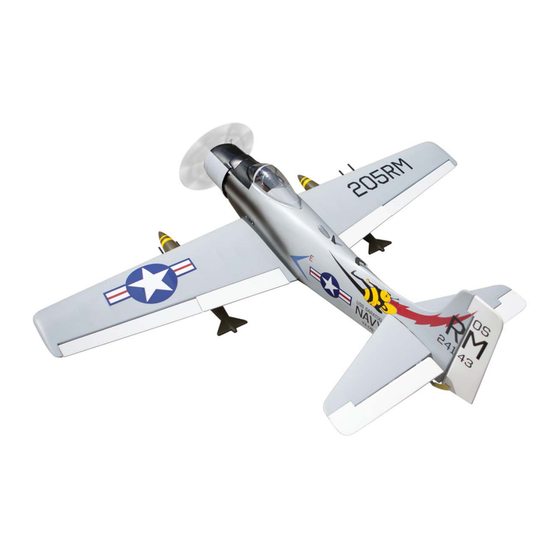
Specifications:
Wingspan---------------63.0 in (160 cm).
Wing area---------------637.1 sq.in (41.1 sq.dm).
( BEE VERSION )
Weight-------------------8.6lbs (3.9 kg).
Length-------------------47.8 in (121.5cm).
Engine-------------------10cc - 15cc
A
R
F
LMOST
EADY TO
LY
Radio---------------------6 channels with 7 servos.
Electric conversion: Optional.
www.seagullmodels.com
1
Advertisement
Table of Contents

Related Manuals for Seagull Models SEA230B


Summary of Contents for Seagull Models SEA230B
- Page 1 WWW.SEAGULLMODELS.COM A S S E M B L Y M A N UA L “ Graphics and specifications may change without notice “ . MS: 230B Specifications: Wingspan---------------63.0 in (160 cm). Wing area---------------637.1 sq.in (41.1 sq.dm). ( BEE VERSION ) Weight-------------------8.6lbs (3.9 kg).
-
Page 2: Kit Contents
WARBIRD 10cc-15cc INTRODUCTION. Thank you for choosing the Skyraider WARBIRD 10cc-15cc ARTF by SEAGULL MODELS COMPANY LTD,. The Skyraider WARBIRD 10cc-15cc was designed with the intermedi- ate/advanced sport flyer in mind. It is a semi scale airplane which is easy to fly and quick to assemble. -
Page 3: Additional Items Required
WWW.SEAGULLMODELS.COM HINGING THE FLAP. KIT CONTENTS. Skyraider SEA230 WARBIRD 10cc-15cc SEA23001 Fuselage SEA23002 Wing set SEA23003 Tail set SEA23004 Canopy SEA23005 Pilot SEA23006 Cowling SEA23007 Aluminium tube ADDITIONAL ITEMS REQUIRED. M2x10mm 10cc-15cc gasoline engine. Computer radio with 7 servos. Glow plug to suit engine. Propeller to suit engine. -
Page 4: Hinging The Aileron
Skyraider Instruction Manual. WARBIRD 10cc-15cc Hinge. 3) Slide the wing panel on the aileron until there is only a slight gap. The hinge is now centered on the wing panel and aileron. Re- move the T-pins and snug the aileron against the wing panel. -
Page 5: Hinging The Rudder
WWW.SEAGULLMODELS.COM 5) Turn the wing panel over and deflect the HINGING THE RUDDER. aileron in the opposite direction from the opposite side. Apply thin C/A glue to each Glue the rudder hinges in place using hinge, making sure that the C/A penetrates the same techniques used to hinge the ai- into both the aileron and wing panel. - Page 6 Skyraider Instruction Manual. WARBIRD 10cc-15cc INSTALL FLAP CONTROL HORN. Install the flap control horn using the same method as same as the aileron con- trol horns. Epoxy. Elevator fiberglass control horn. Fiberglass control horn. INSTALL RUDDER CONTROL HORN. Repeat steps to install the rudder control horn as same as steps done for ailerons.
- Page 7 WWW.SEAGULLMODELS.COM 1) Install the rubber grommets and brass INSTALLING THE SWITCH RECEIVER. collets onto the throttle servo. Test fit the servo into the aileron servo mount. Install the switch into the precut hole in the side, in the fuselage. 2) Secure the servos with the screws pro- vided with your radio system.
-
Page 8: Installing The Stopper Assembly
Skyraider Instruction Manual. WARBIRD 10cc-15cc Vent tube. Fuel pick up Switch. INSTALLING THE STOPPER Fuel fill tube. ASSEMBLY. 3) Carefully bend the second nylon tube up 1) Using a modeling knife, carefully cut at a 45º angle. This tube is the vent tube. off the rear portion of one of the 3 nylon tubes leaving 1/2”... -
Page 9: Engine Mount Installation
WWW.SEAGULLMODELS.COM 7) Slide the fuel tank into the fuselage. Guide the lines from the tank through the hole in the firewall. Vent tube. 8) Use plywood template to hold in place the fuel tank with C/A glue to secure the fuel tank inside the fuselage. - Page 10 Skyraider Instruction Manual. WARBIRD 10cc-15cc 2) Use four 4x30mm head bolts and four 3) Use a drill to drill the four holes in the 4mm washers to attach the engine mount engine mount rails. rails to the firewall. Tighten the screws . Make sure to use threadlock on the screws to help prevent them from vibrating loose.
- Page 11 WWW.SEAGULLMODELS.COM 9) Move the throttle stick to the closed po- Pushrod wire. sition and move the carburetor to closed. Use a 2.5mm hex wrench to tighten the screw that secures the throttle pushrod wire. Make sure to use threadlock on the screw so it does not vibrate loose.
- Page 12 Skyraider Instruction Manual. WARBIRD 10cc-15cc Drill hole C/A glue Cut. Knife. Epoxy.
- Page 13 WWW.SEAGULLMODELS.COM 1) Slide the fiberglass cowl over the en- gine and line up the back edge of the cowl with the marks you made on the fuselage then trim and cut as shown. Because of the size of the cowl, it may be nec- essary to use a needle valve extension for the high speed needle valve.
- Page 14 Skyraider Instruction Manual. WARBIRD 10cc-15cc - Model size: .75-.90 size models - Motor: 50mm 310 rev per volt - Propeller: 14x10 ~ 15x10 - ESC: 60A - Lipo Batteries: 8 cell 3200mA 3) Attach the electric motor box to the firewall suitable with the cross lines drawn on the electric motor box and fire- wall.
- Page 15 WWW.SEAGULLMODELS.COM Epoxy 4 mm 145 mm Balsa stick. 4 mm Epoxy 6) Attach the speed control to the side of the motor box using two-sided tape and tie wraps. Connect the appropriate leads from the speed control to the mo- tor.
-
Page 16: Installing The Aileron Servos
Skyraider Instruction Manual. WARBIRD 10cc-15cc Tie wraps. INSTALLING THE AILERON SERVOS. 3x15mm INSTALLING THE PROPELLER. Servos Small weight Thread Because the size of servos differ, you may need to adjust the size of the precut opening in the mount. The notch in the The propeller should not touch any sides of the mount allow the servo lead to part of the spinner cone. - Page 17 WWW.SEAGULLMODELS.COM 3) A string has been provided in the wing to pull the aileron lead through to the wing root. Remove the string from the wing at the servo location and use the tape to attach it to the servo extension lead.
-
Page 18: Installation
Skyraider Instruction Manual. WARBIRD 10cc-15cc INSTALLING THE FLAP SERVO. Bend at the mark Repeat the procedure for the aileron servo. M2 lock nut. Metal clevis. Snap keeper. Servo arm. Snap keeper. AILERON PU SHROD HORN INSTALLATION. Please see below pictures. Nylon Snap keeper. - Page 19 WWW.SEAGULLMODELS.COM INSTALLING WIRE LANDING GEAR. Please see these below pictures. 3x15mm Mark. Epoxy. Drill.
- Page 20 Skyraider Instruction Manual. WARBIRD 10cc-15cc Collar. INSTALLING THE BOMB ONTO THE WINGS. Collar.
-
Page 21: Optional Retractable Landing Gear
WWW.SEAGULLMODELS.COM OPTIONAL RETRACTABLE LANDING GEAR. Retractable landing gear is not included in this kit, however itis a very popular add-on option. If you want to use retracts in your Skyrasider, we recommend that you buy a good set of electric ratating retracts rated for 30-120 size airplanes - such as the E-Flite 60-120 95 degree Elec- tric Rotating Retract EFLG520 shown... - Page 22 Skyraider Instruction Manual. WARBIRD 10cc-15cc Cut. Epoxy. Cut. Epoxy. Epoxy.
-
Page 23: Installing The Tail
WWW.SEAGULLMODELS.COM INSTALLING THE TAIL. Epoxy. Slide the vertical stabilizer back inplace. Using a triangle, check to ensure that the vertical stabilizer is aligned 90º to the horizontal stabilizer. - Page 24 Skyraider Instruction Manual. WARBIRD 10cc-15cc ELEVATOR PU SHROD HORN INSTALLATION. Vertical Stabilizer. 1) Locate items necessaryto install rud- Horizontal 90º Stabilizer. der pushrod. 2) Install the elevator control horn using the same method as with the aileron con- trol horns. 3) Position the elevator control horn on the both side of elevator.
- Page 25 WWW.SEAGULLMODELS.COM RUDDER PUSHROD HORN INSTALLATION. 1) Locate items necessaryto install rud- der pushrod. Cut. M2 clevis. M2 lock nut. Elevator control horn. Rudder control horn. Rudder pushrod.
-
Page 26: Mounting The Tail Wheel
Skyraider Instruction Manual. WARBIRD 10cc-15cc Screw. M2 clevis. Fuel tubing. MOUNTING THE TAIL WHEEL. 1) Locate the items necessary to install tail gear. - Page 27 WWW.SEAGULLMODELS.COM INSTALLATION PILOT AND CANOPY. 1) Locate items necessary to install pilot, seats. 2) A scale pilot is included with this ARF. The Seagull Pilot included fitting well to the cockpit. (or you can order others scale pilot figures made by Seagull factory. They are available at Seagull distributors.) If you are going to install a pilot figure, please use a sanding bar to sand the base...
-
Page 28: Apply The Decals
Skyraider Instruction Manual. WARBIRD 10cc-15cc Epoxy. Epoxy. 4) Position the canopy onto the fuselage. Trace around the canopy and onto the fu- APPLY THE DECALS. selage using a felt-tipped pen. 1) If all the decals are precut and ready to stick. - Page 29 WWW.SEAGULLMODELS.COM 2) Wrap the receiver and battery pack in 3) Tighten the antenna to the fuselage. the protective foam rubber to protect The antenna is removeable so you can in- them from vibration. stall it at the flying field to prevent dam- age in transporting.
- Page 30 Skyraider Instruction Manual. WARBIRD 10cc-15cc Wing bolt. ATTACHMENT WING- FUSELAGE. Attach the aluminium tube into fuselage. Wing tube. Insert two wing panels as pictures below.
-
Page 31: Control Throws
WWW.SEAGULLMODELS.COM With the wing attached to the fuselage, BALANCING. all parts of the model installed ( ready to fly), and empty fuel tanks, hold the model 1) It is critical that your airplane be at the marked balance point with the sta- balanced correctly. - Page 32 Skyraider Instruction Manual. WARBIRD 10cc-15cc...
-
Page 33: Flight Preparation
WWW.SEAGULLMODELS.COM FLIGHT PREPARATION. PREFLIGHT CHECK. Check the operation and direction 1) Completely charge your trans- of the elevator, rudder, ailerons and mitter and receiver batteries before throttle. your first day of flying. A) Plug in your radio system per the 2) Check every bolt and every manufacturer’s instructions and turn Skyraider...
Need help?
Do you have a question about the SEA230B and is the answer not in the manual?
Questions and answers