Advertisement
EC70A-SU Installation Guide
• 1 EC70A-SU system unit
• Mounting screws for SATA drive
• Mounting screws for Mini PCIe module
• 1 Quick Installation Guide
• 1 CD disk includes:
- Drivers / Manual
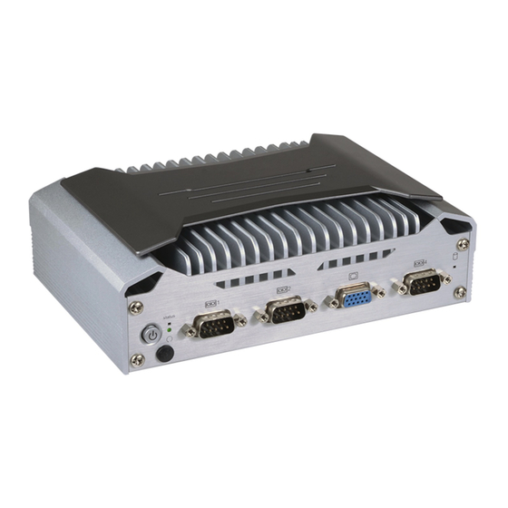
Front View
Rear View
DFI reserves the right to change the specifi cations at any time prior to the product's release. For the latest revision and details of the
installation process, please refer to the user's manual.
Package Contents
Panel
Status LED
(blue)
Power
(green)
Reset
COM 1
COM 2
HDMI
USB 3.0
COM 3
Line-out
Antenna
Switch
hole
1
www.dfi .com
HDD LED
(blue)
VGA
COM 4/ 8-bit DIO
Mic-in
USB 3.0
Antenna
LAN 1~2 DC-in
hole
Advertisement
Table of Contents

Related Manuals for DFI EC70A-SU


Summary of Contents for DFI EC70A-SU
- Page 1 LAN 1~2 DC-in hole hole DFI reserves the right to change the specifi cations at any time prior to the product's release. For the latest revision and details of the installation process, please refer to the user's manual. www.dfi .com...
- Page 2 Installing a 2.5" SATA Drive 1. Remove the two screws securing the chassis cover and lift the cover to open the system. Chassis screw 2. Locate the SATA drive bay on the system board. Remove 4 mounting screws that secure the drive bay to the system board.
- Page 3 4. Place the SATA with the attached drive bay to the system and connect the SATA cable to the SATA connectors on the system board. SATA power connector SATA data connector SATA cable Mounting screw 5. Secure the SATA drive bay with the mounting screws you removed in step 1. Mounting screw...
- Page 4 Installing a Mini PCIe Card The system board is equipped with 2 Mini PCIe slots: one full-size and one half-size slot. Here we will demonstrate the installation of a full-size Mini PCIe card. Grasp the Mini PCIe card by its edges and align the notch in the connector of the PCIe card with the notch in the connector on the system board.
- Page 5 Board Layout and Jumper Settings COM 3 LAN 2 LAN 1 SATA 2 SATA Power USB 4 USB 2 USB 3 USB 1 DC-in LINE-out MIC-in USB 3.0 USB 3.0 Realtek ALC888 SATA 3.0 Intel WGI210AT DDR4 DDR4 DDR4 DDR4 Battery SPI Flash Auto PWR ON...
Need help?
Do you have a question about the EC70A-SU and is the answer not in the manual?
Questions and answers