Table of Contents
Advertisement
Quick Links
724 Robbins Road, Grand Haven, MI 49417 Phone: 616-842-7110 800-937-3253
Fax: 616-842-0859 800-846-3253
Web:
www.dakecorp.com
E-mail:
customerservice@dakecorp.com
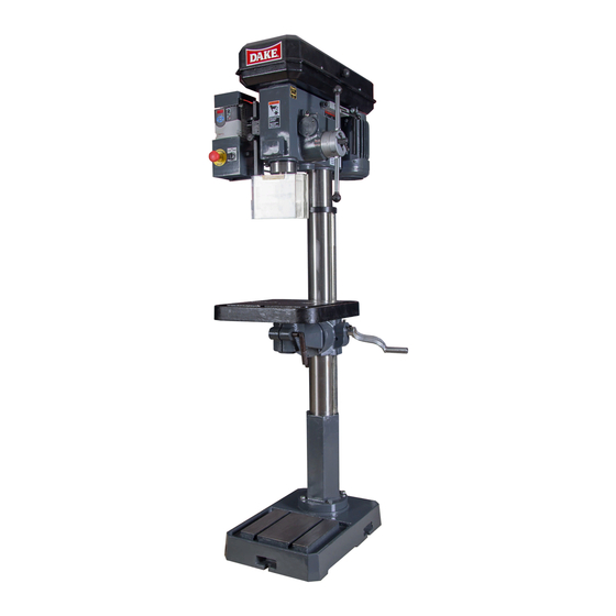
SB-250V Drill Press
OWNERS MANUAL
FOR YOUR OWN SAFETY AND
OPTIMUM OPERATION READ
INSTRUCTION MANUAL BEFORE
OPERATING DRILL PRESS
RETAIN THIS MANUAL FOR
FURTHER REFERENCE.
Model: SB-250V
4/1/14
Advertisement
Table of Contents

Related Manuals for Dake SB-250V


Summary of Contents for Dake SB-250V
- Page 1 724 Robbins Road, Grand Haven, MI 49417 Phone: 616-842-7110 800-937-3253 Fax: 616-842-0859 800-846-3253 Web: www.dakecorp.com E-mail: customerservice@dakecorp.com SB-250V Drill Press OWNERS MANUAL FOR YOUR OWN SAFETY AND OPTIMUM OPERATION READ INSTRUCTION MANUAL BEFORE OPERATING DRILL PRESS RETAIN THIS MANUAL FOR FURTHER REFERENCE.
- Page 2 Distributed by: Trick-Tools 75 Truman Road Pella, IA 50219 Phone:1-877-VAN-SANT E-mail: sales@trick-tools.com Here at Trick Tools we believe that our customers deserve the best value in their tool and equipment purchases. We are constantly at work searching out a variety of high quality, high performance tools to offer at the best prices possible.
-
Page 3: Table Of Contents
TABLE OF CONTENTS • Model specifications, uncrating and installation page 2 • Safety Precautions page 3 - 4 • Controls page 5 • Basic tapping instructions and tips page 6 • Operation instructions basic page 7 • Tool removal page 8 •... -
Page 4: Model Specifications, Uncrating And Installation
MODEL AND SPECIFICATIONS Machine Specifications: Model SB-250V Drill Type Floor Max. Tap Capacity Max. Drill Capacity 1” Spindle Taper Spindle Travel 5” Max. Work Diameter 18” Speeds (Step Pulley) Spindle Speed Range 68-1381 Column Diameter 3-5/8” Table 14 x 14”... -
Page 5: Safety Precautions
properly and perform its intended function. Check for alignment of moving parts, binding of moving parts. Breakage of parts or mountings and any other conditions that affect its operation. SAFETY Keep guards in place and in working order. Remove adjusting key and wrenches. Be in the habit of checking to see that keys and adjusting wrenches are removed from tool before turning it on. - Page 6 Do not open any cover or remove any guard without proper lockout of equipment. Only a qualified electrician with proper PPE should perform electrical work on this equipment. Some components in this equipment may store electricity. BEFORE USE, ALL SAFETY POINTS MUST BE READ AND UNDERSTOOD! Operation of the drill press incorrectly, or in a dangerous fashion can result in serious injury or death.
-
Page 7: Controls
Familiarize yourself with the controls before operating. Emergency stop button When this is pressed the power to the motor and controls is disconnected. The frequency drive stores energy this will remain lit for about 20 seconds. Spindle direction Turn the spindle direction switch to the desired direction forward, reverse or stop. If the emergency stop button is pushed or if the power is lost you will have to move this to stop (TO RESET) then to desired spindle direction. -
Page 8: Basic Tapping Instructions And Tips
Tapping operations using the reverse feature Drill the initial hole on the drill press for accuracy of diameter. If the diameter is 1/2 inch or larger, drill a pilot hole about half that diameter first. Make sure the hole has a large enough chamfer. If the chamfer is too small the tap will work a little hard when starting the tapping operation. -
Page 9: Operation Instructions Basic
1. BASIC OPERATION (PROCEDURE) Drill / Chuck Installation: To show greater detail Chuck guard is in the open position in POWER MUST BE OFF BEFORE photos. CHUCK GUARD MUST IN MAKING ANY ADJUSTMENTS! PLACE DURING OPERATION! TURN POWER OFF! Before inserting drill bits, chucks or arbors, always clean out spindle hole and taper hole with a clean cloth. -
Page 10: Tool Removal
Note: • Always use sharp, straight bits. • Never use bits with turned down shafts. • Never exceed the maximum diameter bit size for the machine. • Always wear appropriate clothing while operating the drill press. • All guards and interlocks must be in place when operating the machine. - Page 11 Table lock Table height adjustment: Table height adjustment is accomplished by loosening the clamp Bolt, then adjusting the table with the bracket handle to desired height. After table is at working height, retighten the clamp bolt securely. Note: Keep table adjustment rack clean from debris.
-
Page 12: Spindle Depth And Feed Operation
SPINDLE DEPTH AND FEED OPERATION DEPTH LOCKING HANDLE DEPTH LOCKING GAUGE ZERO POINTS AUTO FEED HANDLE POSITION MANUAL FEED HANDLE POSITION Depth setting Loosen the depth locking handle by turning it counter clockwise. When this is loose you can turn the depth gauge to the desired depth. Zigzag line is for auto feed depth operations Straight line is for manual depth feed operations After setting depth tighten the depth locking handle. -
Page 13: Proper Drill Speeds For Materials And Bit Diameter
The proper drill speed for a given drill bit size is as on following table: Material Cast Tool Steel Cast Iron Mild Steel Alum. & Type Steel Copper SURFACE FEET PER MINUTE s.f.m. s.f.m. s.f.m. s.f.m. s.f.m. Drill Dia. Inch REVOLUTIONS PER MINUTE 1/16 2,445... -
Page 14: Rapid Range Change Rpm Chart
With the motor running (NOT ON THE HIGHEST SPEED), push or pull the range change handle and at the same time change the adjustment handle to the desired range. See chart below for ranges. SB-250V RPM Chart High Low speed... -
Page 15: Machine Maintenance
2. MAINTENANCE OF MACHINE MAINTENANCE 1. On a regular basis blow out any dust that may accumulate inside the motor. (Frequency depends on environment the machine is 2. A coat of automotive wax applied to the table and column will help to keep the surface clean. -
Page 16: Parts Diagram And Parts List
See page 18... - Page 17 PARTS LIST for SB-250V Item Description SB-250V Qty. Description SB-250V Qty. Item No. Spring Spindle Pulley 301088 Clutch Claw Insert Pulley 302218 Clutch Claw Base Shaft C-Ring Ring Gear- Clutch Bearing 6203Z 300987 Pinion Shaft Ring Spring Cap Base Bearing Spring &...
- Page 18 Item Description SB-250V Qty. Description SB-250V Qty. Item No. Worm shaft vertical Worm Shaft Base Screw Bearing Cover Pulley holder Bolt Spring Bolt Bolt Washer Pulley 301089 37, 38, Lock handle Bearing Knob Spacer Bearing Handle Handle Base Handle washer...
- Page 19 PEDISTEL PARTS BREAKDOWN Description SB-250V Description SB-250V Item No. Item No. Base 301040 Clamp Bolt 301049 Flange 301042 Clamp Bolt 301051 Spring Washer (4x) 13 mm Table Arm 301052 Table Screw 300999 301055 Bracket Column 301044 Worm 301056 Rack 301047...
- Page 20 ADDITIONAL PARTS LIST Parts list Item # Part name Part # Qty. Top cover 87377 Drive unit 302704 Name plate emergency stop 301904 Emergency stop button 716538 Back mounting plate 87378 Bracket 87382 Name plate reverse stop forward 302746 Selector Switch 302730 Switch mounting box 87379...
-
Page 21: Troubleshooting Matrix
TROUBLESHOOTING GUIDE Problem Possible Cause Remedy Machine does not turn on Not plugged in Plug into proper receptacle Frequency drive has error Clear error by turning off then back on Too long or not correct extension Remove extension cord and plug directly cord into receptacle Emergency stop button is activated... -
Page 22: Electrical Warning
ELECTRICAL WARNING 1. In the event of a malfunction or breakdown, grounding provides a path of least resistance for electric current to reduce the risk of electric shock. This machine is equipped with an electric cord having an equipment grounding conductor. The proper plug must be used that is properly installed and grounded in accordance with all local codes and ordinances. -
Page 23: Electrical Diagram
ELECTRICAL DIAGRAM...
Need help?
Do you have a question about the SB-250V and is the answer not in the manual?
Questions and answers