Advertisement
Quick Links
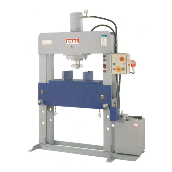
FORCE 40, 70, 100 & 150 Ton
Use and Maintenance Manual
Model No: _________________
Serial No: _________________
Force 40 70 100 150 Ton
724 Robbins Road
Grand Haven, Michigan 49417
616-842-7110
616-842-0859
Web:
E-mail:
Dura Press Models
Dual voltage machines for 220 / 440 volts
Phone 800-937-3253
Fax 800-846-3253
www.dakecorp.com
customerservice@dakecorp.com
technicalsupport@dakecorp.com
1
Advertisement

Related Manuals for Dake FORCE 40


Summary of Contents for Dake FORCE 40
- Page 1 Fax 800-846-3253 Web: www.dakecorp.com E-mail: customerservice@dakecorp.com technicalsupport@dakecorp.com Dura Press Models FORCE 40, 70, 100 & 150 Ton Dual voltage machines for 220 / 440 volts Use and Maintenance Manual Model No: _________________ Serial No: _________________ Force 40 70 100 150 Ton...
- Page 2 Part number 300168 Part number 84935 Part number 84487 Part number 84399 If at any time these safety stickers need to be replaced or are missing lock out the machine and contact Dake immediately. Force 40 70 100 150 Ton...
- Page 3 All work requiring the piece to be pressed to be supported by the operator is forbidden. It is strictly forbidden to press, cut, draw and do anything else with pieces whose dimensions or physical nature may explode or produce splinters. Force 40 70 100 150 Ton...
-
Page 4: Safeguarding The Point Of Operation
ANSI B11.2 – Hydraulic Power Presses Safety Requirements for Construction, Care and Use It is important that Dake press users have a clear understanding of their responsibility involving the care and use of their Dake hydraulic press, including point-of-operation safe guards. Dake strongly recommends that Dake press users obtain a copy of the current American National Standard Institute (ANSI) B11.2 standard, for a more complete understanding of their... - Page 5 The press is fitted with a rating plate fixed in a visible manner on the front as shown in Fig. 1 item 1 on next page. The Dake part number and serial number on the front name plate shown in Fig.
- Page 6 Do not position on unstable or unleveled floor. Below in fig. 4 is the allowable distance from the wall, other machines or other objects. Fig. 4 Commissioning and Starting Electrical connection Force 40 70 100 150 Ton...
- Page 7 The amount of oil required for each model is described in the chart below. 40 Ton 10.5 Gallons 70 ton 10.5 Gallons 100 Ton 15.5 Gallons 150 Ton 22.5 Gallons Force 40 70 100 150 Ton...
- Page 8 Fig 7. 5. Screw down inspection cap. If the motor rotates in the wrong direction: See your electrician. Fig. 7 Any damage caused by wrong electrical connection is not covered by warranty Force 40 70 100 150 Ton...
- Page 9 HD-68 To obtain best results oil temperature should not exceed 140 F. When using DTE No. 26 as an Alternative for DTE No. 24 there might be a slight variation in the ram speeds. Force 40 70 100 150 Ton...
- Page 10 Adjustment of the maximum pressure must be made starting from the lower value and gradually increasing to reach the pressure necessary to perform the operation to be carried out. Dake declines all liability for damage to things and/or persons caused by tampering with the pressure control valve fitted on the unit.
- Page 11 7. Check to be sure the position and the assembly of the pins are correct. 8. Unhook the chains and leave them hang in a downward position (Pos. 5). Pos. 6 Pos. 2 Pos. 3 Pos. 1 Pos. 5 Force 40 70 100 150 Ton...
- Page 12 It is recommended to change the filter after the first 100 hours of operation. After that approximately every 500-600 hours. Force 40 70 100 150 Ton...
- Page 13 Air inlet filter Replacing the filters will help give the pump, oil and generally all the moving components longer service life. Failure to comply with the maintenance table in changing the filter will forfeit the warranty. Force 40 70 100 150 Ton...
- Page 14 Poor quality oil Excessive wear on High operating pressure Lowe the setting of the pressure relief parts Foreign bodies in the oil not held valve back by the filter Insufficient filtering, replace the filters Force 40 70 100 150 Ton...
- Page 15 When going for demolition the press must be treated as special waste, it must therefore be split up into its homogeneous parts, these parts must be separately disposed of in conformity with local and state laws along with all OSHA regulations. Force 40 70 100 150 Ton...
- Page 16 Power light 300298 Main power switch 302169 Elect. Box lock 300628 Door key 80511 Female plug Male plug 301547 Electrical box w/ all components 300387 Electrical box w/ no components 300389 Power Switch Shaft 302729 Force 40 70 100 150 Ton...
- Page 17 302189 302192 302192 N.O. contact block 302192 72300000 72300000 Relay 72300000 300843 300843 Fuse block 300843 77523 77523 Fuse 2 amp 77523 Terminal block ground Terminal block black 302728 302728 On-Off Switch Body 302728 Force 40 70 100 150 Ton...
- Page 18 Part # 40 Ton Part # 70 Ton Part # 100 Ton Part # 150 Ton Item # Part Name Complete relief 300178 300178 300178 valve O-ring kit spring washer 301393 301393 301393 Valve handle Force 40 70 100 150 Ton...
- Page 19 6, 9, 10 body 302210 Relief valve 300852 Not shown Cover Body 302209 Gasket Set 300886 Back valve body entry collector body max valve 302208 11, 12, 13 Lever and knob only 302341 1 & 2 Force 40 70 100 150 Ton...
- Page 20 300359 Not shown Hydraulic hose B port 300382 300382 Not shown Hydraulic hose A port 300383 300383 Not shown Eye bolt 301880 301880 301880 Not shown Nose piece bolt 300793 300793 300793 Not shown Force 40 70 100 150 Ton...
- Page 21 Pump motor 302200 302200 Blade 302056 302056 Pumping bearing Eccentric Roller bearing High pressure pump group 301115 301115 301115 Outlet filter / bottom of pump 300393 300393 300394 Motor windings w/ shell 301848 301848 Force 40 70 100 150 Ton...
-
Page 22: Hydraulic Diagram
Hydraulic diagram Force 40 70 100 150 Ton... -
Page 23: Electrical Schematic
Electrical schematic Force 40 70 100 150 Ton... - Page 24 25 Tons 196 Bar 2847 PSI 20 Tons 157 Bar 2277 PSI 15 Tons 117 Bar 1708PSI 10 Tons 78 Bar 1138 PSI 5 Tons 39 Bar 569 PSI 1 Ton 7.8 Bar 114 PSI Force 40 70 100 150 Ton...
- Page 25 110 Bar 1605 PSI 20 Tons 88 Bar 1284 PSI 15 Tons 66 Bar 963 PSI 10 Tons 44 Bar 642 PSI 5 Tons 22 Bar 321 PSI 1 Ton 4.4 Bar 64 PSI Force 40 70 100 150 Ton...
- Page 26 87 Bar 1268 PSI 20 Tons 70 Bar 1014 PSI 15 Tons 52 Bar 761 PSI 10 Tons 35 Bar 507 PSI 5 Tons 17 Bar 253 PSI 1 Ton 3.4 Bar 50 PSI Force 40 70 100 150 Ton...
Need help?
Do you have a question about the FORCE 40 and is the answer not in the manual?
Questions and answers