Advertisement
SETTING UP THE PRESS FOR OPERATION
For shipping convenience, the gauge, pump handle, hoist crank, screw nose and base angles were removed
from the press. Assemble these parts to the press in the following order:
1. Bolt the base angles to the uprights using the four bolts and nuts furnished. Shoulder the base angles
against the stops on the uprights.
2. Install the pressure gauge using a hydraulic sealant to ensure a sealed fit.
3. Insert pump handle into handle socket and fasten in place by means of the setscrew on top of the handle
socket.
4. CAUTION! Place the hoist crank on the lift drum shaft. The table is raised to the desired height by
turning the crank after removing the table pins. Check to make sure the hoist cable is tracking
correctly. Run the table channels from top to bottom. The cable should be on each of the two
upper pulleys and should track back and forth on the cable drum. Always place table pins under
the table channels before releasing the hoist crank when positioning the table channels for cable
tracking, servicing, or set-up for desired work opening. If a tracking problem exists, contact the
Dake factory for instructions. Be sure all table pins are fully inserted in place before applying
pressure. Always remove or release pressure on the cable before pressure is applied.
5. Fasten nosepiece to the end of the screw using the thumbscrew included.
OPERATIONS AND CONTROLS
The operator should acquaint himself with the use of the following controls:
1. The pump handle is the pressure supply source and is manually operated with an up and down motion.
2. Item number 45 (Part no. 10631) is the release valve handwheel. Always keep it firmly closed when
operating the press and it should only be opened when releasing the pressure to allow the ram to return.
3. By turning Item 25 (Part No. 716519), the ram screw can be adjusted into or out of the piston assembly.
Always keep the portion of the screw extending out of the piston as short as possible. It is advisable to
raise the table one or two sets of holes rather than running the screw out to its limit of travel.
EXCEED THE RECOMMENDED STROKE OF 4 INCHES FOR THIS PRESS. EXCEEDING THE
STROKE WILL CAUSE DAMAGE TO THE INNER PACKINGS.
4. The two combination table plates-v blocks provided are used for supporting the work while it is being
straightened.
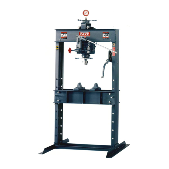
50H Press
INSTRUCTIONS AND PARTS
LIST FOR MODEL 50H
HAND-OPERATED HYDRAULIC PRESS
1
NEVER
2/2014
Advertisement
Table of Contents

Related Manuals for Dake 50H


Summary of Contents for Dake 50H
- Page 1 If a tracking problem exists, contact the Dake factory for instructions. Be sure all table pins are fully inserted in place before applying pressure. Always remove or release pressure on the cable before pressure is applied.
-
Page 2: Safeguarding The Point Of Operation
Safety Requirements for Construction, Care and Use It is important that Dake press users have a clear understanding of their responsibility involving the care and use of their Dake hydraulic press, including point-of-operation safe guards. Dake strongly recommends that Dake press users obtain a copy of the current American National Standard Institute (ANSI) B11.2 standard, for a... -
Page 3: Ordering Information
This person should be conscious of the press ram movement not only for himself but also for persons in the immediate area of the machine. Label 84487 Label 300168 Label Placement View Label 84399 Label 6767 Label 607 50H Press 2/2014... - Page 4 TROUBLE SHOOTING – DAKE HAND HYDRAULIC PRESSES PUMP PACKING LEAKAGE If oil leaks past the pump packing, tighten the pump packing nut (551) until pump handle works hard, then slack off just enough to cause the handle to stay in position by itself. After long periods of operation, it may be necessary to install new pump packings.
-
Page 5: Handpump Assembly
1129 Valve Rod Packing Nut Valve Rod Packing 3/8” Pipe Plug 3/8”-16 x 5/8” Set Screw 43589 Pump Gasket Hand Pump Assembly Complete 700887 Repair Kit – Cylinder & Hand Pump Assembly 701291 (Includes – Items 5,8,17,20,26B,27,34,38) 50H Press 2/2014... - Page 6 716222 Piston Leather (Serial No. < 192522) Packing Ring (Serial No. > 192523) 17878 Cylinder – 50 Ton Handwheel 716521 Yoke Gasket, Cylinder 1268 Repair Kit – Cylinder & Hand Pump Assembly 701291 (Includes – Items 5,8,17,20,26B,27,34,38) 50H Press 2/2014...
-
Page 7: Frame Assembly
FRAME ASSEMBLY Item Description Part No. Gauge 71266 Bushing 81384 Gauge Extension Roller Roller Screw Dake Name Plate 81002 Air Vent Tube Handwheel 10631 V-Block Table Plate Table Pins Table Channel 701091 Frame only 700116 Base Angle 3/8 NPT 37° Fitting...
Need help?
Do you have a question about the 50H and is the answer not in the manual?
Questions and answers