Advertisement
Quick Links
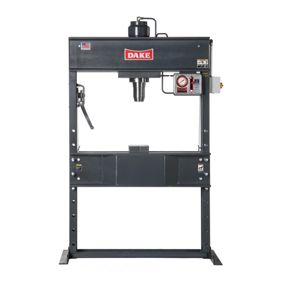
SETTING UP THE PRESS FOR OPERATION
For shipping convenience some of the parts are not assembled. Assemble these parts in the following order:
1. Bolt the base angles to uprights using four bolts and nuts, which are provided. Make sure base
angles are against stops on uprights.
NOTE: The press should set on a level floor with the base angles touching the floor at all
points. Use shims where necessary.
2. Switch box is mounted on left upright. Have electrician connect switch to power line. Pump can rotate
in either direction.
3.
4. Oil Requirements: Fill reservoir thru street elbow at back of press with Mobil DTE oil No. 24 or
equivalent. NOTE: Oil level may be checked (with ram up) by removing the pipe plug on the
right side of reservoir near the front. Replace plug before operating the press.
Model 8-025 uses 3 gallons
Model 8-050 uses 3 gallons
Model 8-075 uses 3 gallons
Model 8-150 uses 10 gallons
5. Attach nose piece to ram by inserting shank into ram and tightening the set screw.
6. CAUTION! Place the hoist crank on the lift drum shaft. The table is raised to the desired height
by turning the crank after removing the table pins. Check to make sure the hoist cable is
tracking correctly. Run the table channels from top to bottom. The cable should be on each of
the two upper pulleys and should track back and forth on the cable drum. Always place table
pins under the table channels when servicing or tracking the cable. If a tracking problem
exists, contact the Dake factory for instructions. Be sure all table pins are fully inserted in
place before applying pressure. Always remove or release pressure on the cable before
pressure is applied.
Model 8-025, 8-050, 8-075 & 8-150
INSTRUCTIONS AND PARTS LIST FOR
Models 8-025, 8-050, 8-075, and 8-150
1
Elec-Draulic II Presses
03/14
Advertisement

Related Manuals for Dake 8-025


Summary of Contents for Dake 8-025
- Page 1 If a tracking problem exists, contact the Dake factory for instructions. Be sure all table pins are fully inserted in place before applying pressure. Always remove or release pressure on the cable before pressure is applied.
-
Page 2: Safeguarding The Point Of Operation
Safety Requirements for Construction, Care and Use It is important that Dake press users have a clear understanding of their responsibility involving the care and use of their Dake hydraulic press, including point-of-operation safe guards. Dake strongly recommends that Dake press users obtain a copy of the current American National Standard Institute (ANSI) B11.2 standard, for a... - Page 3 1. Handcrank is provided to raise and lower table channels to proper height for work. When desired height is obtained insert table pins. Models 8-025 and 8-050 use 2 pins on each side (4 total) and Models 8-075 and 8-150 use 3 pins on each side (6 total).
- Page 4 CAUTION: Prolonged building of pressure at each end of the piston stroke may damage the workhead. CAUTION : When disconnecting any parts of this machine be extremely careful that all parts are clean to prevent entrance of dirt in the hydraulic system. Model 8-025, 8-050, 8-075 & 8-150 03/14...
- Page 5 This person should be conscious of the press ram movement not only for himself but also for persons in the immediate area of the machine. Label 84487 Label 300168 Label Placement View Label 84395 Label 36511 Label 84399 84395 300168 76462 84487 Label 76462 84399 Model 8-025, 8-050, 8-075 & 8-150 03/14...
- Page 6 Model 8-025, 8-050, 8-075 & 8-150 03/14...
- Page 7 Model 8-025, 8-050, 8-075 & 8-150 03/14...
- Page 8 Wear Ring 37038 37045 37050 37055 1or2 Oil Seal 1477 1357 1524 PistonGuide 34322 35562 35573 35592 Tube Valve to bot. cyl. Tube valve to top cyl Straight fitting 17920 17920 17920 17920 Model 8-025, 8-050, 8-075 & 8-150 03/14...
- Page 9 5/16 Lockwashers 43644 43644 43644 3/8 Lockwashers 43645 1/8 Soc pipe plug Repair Kit items 39, 40, 43, 44, 45, 711016 711017 711018 711019 46, 51 Table Hoist Assembly items 700112-S 700112-S 22,23,24,25,26,27,31,32,33,34 Model 8-025, 8-050, 8-075 & 8-150 03/14...
- Page 10 37046 37051 Palmetto Ring 17976 17878 17942 37052 Cylinder 34321 35561 35589 35584 Complete assembly 707725 708077 708055 708078 Repair Kit items C, B, D, G, H, K, E 711016 711017 711018 711019 Model 8-025, 8-050, 8-075 & 8-150 03/14...
- Page 11 Items 19,22,23,24 torque to 85 In lbs Model 8-025, 8-050, 8-075 & 8-150 03/14...
- Page 12 ** Note: This kit is completely assembled and pre tested and ready for service. 29662 Dynex valve replaces the Dake valve 26-300 and 26-302. Repair kit for the 26-300 is part number 710146. No repair kit available for the 26-302.
-
Page 13: Electrical Parts List
THIS DIAGRAM IS FOR THE 25, 50 AND 75 TON MODELS ONLY D# 33720 Electrical parts list Part # Part description 302062 Starter enclosure 29796 Switch manual 302187 Motor starter 220 volt Motor starter 440 volt Model 8-025, 8-050, 8-075 & 8-150 03/14... - Page 14 Heater overload (150 66244 ton only) 150 ton model only Model 8-025, 8-050, 8-075 & 8-150 03/14...
- Page 15 1 ½ - 6 2 – 6 2 ½ - 4 3 ½ - 4 724 Robbins Road Grand Haven, MI 49417 Phone: 616-842-7110 800-937-3253 Fax: 616-842-0859 800-846-3253 Web: www.dakecorp.com E-mail: customerservice@dakecorp.com technicalservice@dakecorp.com Model 8-025, 8-050, 8-075 & 8-150 03/14...
Need help?
Do you have a question about the 8-025 and is the answer not in the manual?
Questions and answers