Table of Contents
Advertisement
Quick Links
Advertisement
Table of Contents

Related Manuals for MIMAKI SWJ-320EA


Summary of Contents for MIMAKI SWJ-320EA
- Page 1 MIMAKI ENGINEERING CO., LTD. https://mimaki.com/ D203278-13 Original instructions...
-
Page 2: Table Of Contents
Table of contents CAUTION ..................v DISCLAIMER OF WARRANTY ............v Requests ....................v FCC Statement (USA) ................v Interference to televisions and radios ........... v Foreword ..................v About usable ink ................... v On This Operation manual ..............v Safety Precautions ................vi Symbols .................... - Page 3 Setting two narrow roll media (twin rolls) ..................2-13 Setting leaf media................2-16 Removing the taken-up media ............2-16 Changing the printing origin .............2-17 Preparing for the Heaters............2-18 Changing the Temperature Settings for the Heaters......2-18 Test Printing ................2-18 Test Printing ..................2-19 Head Cleaning ................2-19 About head cleaning.................2-19 Perform head cleaning depending on the test printing result ...2-19 Setting of Media Correction............2-20...
- Page 4 About Information MENU............3-21 Information MENU table ..............3-21 Displaying the Information..............3-22 Displaying the Information of this machine........3-22 Setting a Language..............3-23 Chapter 4 Maintenance Maintenance ................. 4-2 Precautions for Maintenance..............4-2 About Cleaning Solution..............4-2 Cleaning the Exterior Surfaces............4-2 Cleaning the Platen ................4-2 Cleaning The Heater Cover..............4-3 Cleaning the Media Sensor ..............4-3 Cleaning the Media Press ..............4-4...
- Page 5 Warning / Error Messages ............5-7 Warning messages................5-7 Error messages ................5-11 Chapter 6 Appendix Specifications ................6-2 Machine specifications ...............6-2 Ink specifications ................6-3 Supply item list ...................6-4 Setting orders of ink tanks.............6-5 Sheet for inquiry ................6-6...
-
Page 6: Caution
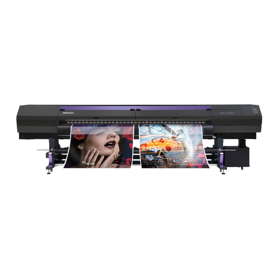
Congratulations on your purchase of MIMAKI color ink jet printer "SWJ-320EA" . Requests “SWJ-320EA” is a color inkjet printer that can print with • This Operation manual has been carefully prepared for solvent ink realizing high speed and high image quality. -
Page 7: Safety Precautions
Failure to observe the instructions given with contact your distributor or a sales office of MIMAKI for this symbol can result in injuries to personnel or repair. Never repair your machine and ink bottle by damage to property. - Page 8 Mimaki immediately. for at least 15 minutes. In doing so, also wash eyes to rinse ink away completely. Then, consult a doctor as soon as possible.
- Page 9 320EA genuine ink. • Pay attention to the expansion and contraction of the media. • Do not use the SWJ-320EA genuine ink with other printers, as Do not use media immediately after unpacking. The media can doing so may cause damage to such machines.
-
Page 10: Safety Interlock
Safety Precautions Cautions on Installation CAUTION A place exposed to direct sunlight On an inclined surface A place that vibrates A place exposed to direct air flow from an A place where temperature or humidity Around a place where fire is used air conditioner or the like. -
Page 11: Warning Labels
Warning labels Warning labels Warning labels are stuck on the machine. Be sure to fully understand the warning given on the labels. If a warning label is illegible due to stains or has come off, purchase a new one from a distributor or our sales office. Around the caridge... - Page 12 Warning labels Reorder Label M905811 M903330 M906144 M907935 M903239 M903404 M910931 M912522 M912523...
- Page 13 Chapter 1 Before Use This chapter describes the items required to understand before use, such as the name of each part of the machine or the installation procedures. About installing this machine ......1-2 Connecting Cables ........1-8 Where to Install This Machine ..... 1-2 Connecting USB2.0 Interface Cable ....1-8 Working Environmental Temperature ..
-
Page 14: Chapter 1 Before Use
Depth Height weight 5410mm 995mm 1440mm 910 kg SWJ-320EA (213.0in) (39.2in) (56.7 in) (2006.2lb) • If the place to install the machine is exposed to strong sunlight around the window, draw a curtain to prevent the machine from being exposed to strong sunlight. -
Page 15: Names Of Parts And Functions
Chapter 1 Before Use Names of Parts and Functions Front Side of the Machine Left side maintenance cover Platen Open the cover in maintenance. The printed media is sent out, sliding on the platen. Even when the power button is off, keep all covers closed. -
Page 16: Rear Side And Right Side Of The Machine
Chapter 1 Before Use Rear Side and Right Side of the Machine Feweding Manual switch Changes the feeding Clamp lever (rear) method (AUTO/MANUAL). Interlocks with the clamp lever in the font of this machine. Feeding direction switch Changes the feeding direction (Forward/Backward/OFF). -
Page 17: Operation Panel
Chapter 1 Before Use Operation Panel Use the operation panel to make settings for printing or operate this machine. Display Local <Setup 1> Changes over the functions of the Displays the following items: function keys ([FUNC1]–[FUNC3]). 3200mm • Printer status PRINT POST •... - Page 18 Chapter 1 Before Use *2 : Functions assigned to [FUNC1] to [FUNC3] Contents of functions assigned to [FUNC1] to [FUNC3] are described below. Icon Contents Displays “MENU” for setting functions. Displays maintenance functions such as test print, cleaning, etc. Shifts to Remote from LOCAL and starts printing. Displays adjustment functions such as Feed Comp, DROP.POScorrect, etc.
-
Page 19: Heater
Chapter 1 Before Use Heater Media sensor Pre-heater, Print heater, and Post-heater are equipped on The media sensor detects the presence of the media. the platen. Pre-heater is used for pre-heating of the media This machine has three media sensors on the pre-heater prior to printing. -
Page 20: Capping Station
PC. Notes on USB 2.0 Interface • Your RIP must be compatible with USB 2.0. When two or more SWJ-320EA machines are connected to one personal computer When two or more SWJ-320EA machines are connected to one personal computer, the personal computer may not Pinch rollers and Feed rollers recognize all the SWJ-320EA machines normally. -
Page 21: Connecting The Lan Cable
When SWJ-320EA is connected to the personal computer to which an external HDD is connected via USB, the speed of data output to SWJ-320EA may drop.That can cause the head unit to stop temporarily at the right or left end during printing. -
Page 22: Connecting Power Supply Cable
Connecting Power Supply Cable and charging You are not allowed to install the printer by yourself. Be sure to request MIMAKI’s service personnel and an electrician to install the printer. Fill ink in the ink tank of this machine. • Be sure to wear the attached safety goggles and •... - Page 23 Chapter 1 Before Use Take out the ink bottle, and slowly shake it Status of ink remaining amount twenty times and more. indicator • To prevent ink from leaking when you shake it, Status of ink Ink near end/ Ink full wear gloves and cover the ink bottle cap with a amount Ink end...
- Page 24 Chapter 1 Before Use About IC chip While checking the ink remaining amount indicator, add ink. • The IC chip has information of ink color, remaining • Depending on the ink type, aluminum sheet amount of ink, expiration data, etc. adheres to the bottle top surface.
-
Page 25: Caution In Handling Of Ink Bottles
15 minutes. In doing so, also wash the eyes to rinse ink away completely. Then, consult a doctor as soon as possible. SWJ-320EA Model • If the ink bottle is moved from a cold place to a Type of Recommended media... -
Page 26: Caution In Handling Of Medias
• Do not leave the media with the heater ON for a long time. Waviness may occur on the media and it may cause media clogging. • Use media recommended by MIMAKI to ensure reliable, high-quality printing. Set the heater temperature to meet the characteristics of the media. - Page 27 Chapter 2 Basic Operations This chapter describes procedures and setting methods for ink and media preparation, and printing. Workflow ............2-2 Test Printing ..........2-17 Turning the Power ON/OFF ......2-3 Test Printing ..........2-18 Head Cleaning ..........2-18 Turning the Power ON ........ 2-3 Turning the Power OFF .......
-
Page 28: Chapter 2 Basic Operations
Chapter 2 Basic Operation Workflow Referring to “Turning the Power ON/OFF” Turning the Power ON/OFF P.2-3). Referring to “Setting a Media” ( P.2-4). Setting a Media Referring to “Test Printing” ( P.2-18). Test Printing Referring to “Head Cleaning” ( P.2-19). Head Cleaning Referring to “Setting of Media Correction”... -
Page 29: Turning The Power On/Off
Turning the Power ON/ Turning the Power OFF When having ended the operation of the machine, turn the power OFF by pressing the power button located on the front side. Check the following items when turning the power OFF. Turning the Power ON •... -
Page 30: Setting A Media
Setting a Media For the Adjusting Lever and the Range This machine can be used with a roll media and leaf Distance Lever position Recommended media between platen media. and head For usable media, refer to P.1-13 “Usable sizes of media”. 1.7mm 0.3mm (0.011in) or less (PVC Vinyl Standard... -
Page 31: Setting A Roll Media
Setting a roll media • Narrow roll media may slip on the wide media set area and feeding cannot be performed properly. For setting a narrow roll media, refer to "Setting a narrow roll media"( P.2-9) When using a take-up device, it is recommended to set the media with its print-side facing inside. - Page 32 On the backside of unit, set the feeding Set the feeding manual switch to "Manual", device. and pull the media a little longer. • Pull the media out of the roll so that the media can be grasped from the front of the machine. Feeding manual Feeding direction switch switch...
- Page 33 Push down the clamp lever to hold the media. Feed the media to the tension bar. (1) Pressing the [] key, feed the media until the tension bar at the rolling side is being hidden. • Check the media end is not caught into the slot on the platen, and feed the media.
- Page 34 Press to feed the media about 10 cm, and then release the lock of the tension bar. Tension bar Media Press Close the front cover. Lock Press the key to select "ROLL" . • If the [Setting the Display of Media Detection] of Machine Setup set in “AUTO”( P.3-15), the machine automatically detects the media width.
-
Page 35: Setting A Narrow Roll Media
About entering media remaining Detecting media width when media amount detection method is “MANUAL” When you set [Media remaining amount display] to “ON” P.3-14), you are prompted to enter the media Press to select a media (roll or remaining amount after completing the setting of the leaf). - Page 36 Move the media press to outside. Insert the paper core into the roll holder R. Media Press Move the roll holder R on the back of this Loosen the screw of the roll holder C then machine. insert the holder into the core of the roll media.
- Page 37 Insert the roll media in this machine. Prepare for the take-up device. Taking-up manual Taking-up direction switch switch Forward Taking-up with the print side Auto facing to the outside. Manual • Insert the media from the end first so that there is Not operated.
- Page 38 Fix the media to the roll shaft. Roll up the media. (1) Route the media from the front side of the (1) Set taking-up direction switch tension bar, and fix the media in the center of “Forward”/ “Backward” according to the the roll shaft with adhesive tape.
-
Page 39: Setting Two Narrow Roll Media (Twin Rolls)
Setting the Logical Seek. Rise the clamp lever. (1) Press [][] to select the set value. • Set value : Media/ Data/ Quality (2) Press the [ENTER] key. • When [Media Remain] of the Machine Setup is "ON" ( P.3-14), you are prompted to enter the media remaining amount. - Page 40 Move the roll holder C to the center of this Set media in the roll holder. machine, and the roller holders R and L to • Set the media one by one. the right and left ends of this machine (1) Set the roll tables as shown in the figure and temporarily place the media on top of the respectively.
- Page 41 Raise the clamp lever in the rear side of Push down the clamp lever. this machine and Insert the roll media. • Check that the roll media are drawn out almost evenly by lightly pulling several points of the media, and then lower the clamp lever. •...
-
Page 42: Setting Leaf Media
Push down the clamp lever and close the Setting leaf media front cover. Unlike roll media, leaf media does not need to be retained • Set the media straight. with the roll holders. Open the front cover and raise the clamp lever. -
Page 43: Changing The Printing Origin
Pull out so that the white plastic collar is After determining the origin, press the inserted into the slot on top of the leg. key. • The printing origin is changed. • When a roll media is set on the narrow roll holder, change the origin, and then rewind the media by hand and set the media without slack. -
Page 44: Preparing For The Heaters
Preparing for the Heat- Test Printing Print a test pattern to check that there are no discharging defects such as nozzle missing (slight touching of ink or nozzle missing). Changing the Temperature Settings for the Heaters Relationship between head row and You can change/save the temperature settings for the test pattern heaters with “Heater”... -
Page 45: Test Printing
Head Cleaning Test Printing Print a test pattern to check that there are no discharging About head cleaning defects such as nozzle missing (slight touching of ink or nozzle missing). Check the printed test pattern result and perform cleaning In addition, you can select the orientation of the test depending on the status. -
Page 46: Setting Of Media Correction
Setting of Media Cor- • Enter a resolution matching the data printed rection usually. This machine changes the media feeding method, depending on the resolution. If you enter a resolution inconsistent with actual printing, it may result in an inappropriate feed amount. Correct the media feed amount to match the type of media you are using. -
Page 47: Correct The Ink Drop Position For Bidirectional Printing
Correct the ink drop Press to enter a correction value of Pattern 1, and press the key. position for bidirec- • Corrected feeding rate: -40 to 40 • Check the test patterns. The position where an tional printing outward feeding line and a return feeding line become one straight line is the correction value. -
Page 48: Printing Data
Printing Data Start printing. • The printing speed may change, depending on the width of the set media or the position of the Starting a Printing Operation print origin even when the same data is printed. This is because of a difference in resolution. •... - Page 49 Chapter 3 Extended Functions This chapter describes the operation procedures for using the machine more conveniently and each setting procedure. About Setup MENU........3-2 Setting a AUTO Power-off ......3-13 Setting Feeding unit........3-13 Setup MENU table ........3-3 Register the optimal print conditions to match Setting Take-up unit........3-13 Setting the Display of Media Remain..3-14 the use ............
-
Page 50: About Setup Menu
Chapter 3 Setup About Setup MENU On Setup MENU, you can set the print conditions to match the media you usually use. : Press this to select SETTING MENU, or to switch to the previous screen. Local <Setup 1> : Press this to use the adjust function. 3200mm : Press this to switch to the next screen. -
Page 51: Setup Menu Table
Chapter 3 Setup Setup MENU table • For each setting item below, you can set it so that the machine may operate according to the value specified when you printed from your RIP software in the connected host PC. • Set Item : DRYING Time/ Vacuum Fan •... -
Page 52: Register The Optimal Print Conditions To Match The Use
Chapter 3 Setup Copy the contents of SETUP 1 to 4 to Register the optimal print conditions [Temporary] to match the use You can use it with changing the part of registration contents of Setup 1 to 4. In this machine, you will be able to register print Select “copy”... -
Page 53: Setting Of Media Correction
Chapter 3 Setup A pattern for media correction is printed and a media- Press to select the location feeding rate is corrected. selected (SETUP 1 to 4), and press the key. • Two bands are printed in the correction pattern. •... -
Page 54: If The Positions Of Dots Shift
Chapter 3 Setup Correcting Media-feeding during Press to select resolution, and Printing press the key. • Resolution : Y300dpi/ Y450dpi/ Y600dpi/ A media-feeding rate can be corrected even in the remote Y900dpi/ Y1200dpi mode or when image data is printed. •... -
Page 55: Setting Of Logical Seek
Chapter 3 Setup • Setup menu appears. Setting of Logical Seek The head’s operation varies depending on the Logical Press to select “Logical Seek”, Seek settings, as shown in the figure below. and press the key. Movement of heads when Logical Seek is “Media”. Press to select a set value, and UNI-DIRECTIONAL... -
Page 56: Setting Of Left And Right Margins
Chapter 3 Setup Press the key. Press to select SETUP 1 to 4, and press the key. • Setup menu appears. Press to set drying time, and press the key. Press the (<<) . • Set the drying time for scanning is completed. To enable the drying time specified in your RIP, Press to select “Refresh”... -
Page 57: Setting Of Maps4
If performing media correction does not resolve feeding You can set the machine so that it counts the number of stripes, use the MAPS (Mimaki Advanced PassSystem) printed files or the length or time has been completed, and function to disperse the pass boundary to make the performs cleaning automatically if required. -
Page 58: Setting Interval Wiping
Chapter 3 Setup • Setting Interval wiping There are “File”, “Length” and “Time” for auto cleaning. When a set time has elapsed, the machine automatically : When the set files has been completed, File wipes the nozzle surfaces of the head to remove any ink the machine performs head cleaning droplets attached to the surfaces. -
Page 59: About Machine Setup Menu
About Machine Setup MENU Common settings are functions for using this machine easily. The following items can be set in Machine settings. : Press this to select Machine Setup MENU, or to switch to the previous screen. Local <Setup 1> : Press this to switch to the next screen. -
Page 60: Machine Setup Menu Table
Chapter 3 Mchine setting Machine Setup MENU table Function name Set value Default Meaning When no operation has been performed for the NONE/ AUTO Power-off ( P.3-13) 30min set time, the power supply is automatically turned 10 ~ 600min “OFF”. You can set the operation method when the ON/ Feeding Unit ( P.3-13) -
Page 61: Setting A Auto Power-Off
Chapter 3 Mchine setting Function name Set value Default Meaning Event Mail Transmit Send the test e-mail. P.3-16) Test Lock Network & (Password is You can freely specify a four digit password so Mail not set) Setting Lock 0000 to 9999 0000 that no one other than an administrator can P.3-20... -
Page 62: Setting The Display Of Media Remain
Press to enter time, and Setting the Display of Media Remain press the key. Whether the screen displays the remaining amount of a • Year/Month/Day/Time selecting: media is set. by the [][] keys. • Year/Month/Day/Time inputting: the remaining amount of a media is by the [][] keys. -
Page 63: Setting The Display Of Media Detection
Set the network Setting the Display of Media Detec- tion Press the (MENU) in Local. Set the following two items in media detection settings. When loading the media, set whether Press to select “Machine Setup” to detect the media width automatically Setting of Media and press the key. -
Page 64: Setting Event Mail Function
Internet environment, failure of the device/ • To reflect network setting, once turn off the power the power supply, etc. Mimaki has absolutely no supply and then turn it on again. responsibility for any damages or loss resulting from non- delivery or delays. - Page 65 Set the event to send an event mail Set the e-mail address Press the (MENU) in Local. Press the (MENU) in Local. Press to select “Machine Setup” Press to select “Machine Setup” and press the key. and press the key. Press the (<<) .
- Page 66 Set the server Press to select “User Name” and press the key. Press the (MENU) in Local. Press to set User Name and press the key. Press to select “Machine Setup” • Press [][][][] to set the user name to use for the authentication.
- Page 67 Chapter 3 Mchine setting Send a test e-mail Press the key. (>>) • “Transmit Test” will be selected. Press the (MENU) in Local. Press the key. • The sent result is displayed. • If sending test e-mail has failed, an error code is Press to select “Machine Setup”...
-
Page 68: Setting The Setting Lock Function
Press the key several times to Setting the Setting Lock function end the setting. You can freely specify a four digit password so that no one other than an administrator can perform network and • If you forget the password, you can press the mail settings. -
Page 69: About Information Menu
About Information MENU The information of this machine can be confirmed. The following items can be confirmed as machine information. : Press this to select Information MENU, or to switch to the previous screen. Local <Setup 1> : Press this to switch to the next screen. 3200mm : Use these to select a setting item. -
Page 70: Displaying The Information
Machine information (Media width/ Serial No. Media width 3200mm Serial No. '00000000 /Version) SWJ-320EA V1.00 “USAGE” of Information Menu is displayed. (1) Press the [FUNC1] (MENU) in Local (2) Press [][] to select “Information”, and Expiration date of ink Ink Expiration press the [ENTER] key twice. -
Page 71: Setting A Language
Setting a Language You can change the displayed language. Press the (MENU) (<<) key in Local. • Language MENU appears. Press to select language, and press the key. • Set Value :日本語 / English / Español / Português / 中文 Press the key several times to end the setting. - Page 72 3-24...
- Page 73 Chapter 4 Maintenance This chapter describes the items required to use this machine more comfortably, which are the methods for the daily care, the maintenance of the ink unit etc. Maintenance ..........4-2 When nozzle missing Cannot Be Solved ..4-12 Precautions for Maintenance ......
-
Page 74: Chapter 4 Maintenance
Chapter 4 Maintenance Maintenance Cleaning the Exterior Surfaces Maintain the machine regularly or as necessary so that its When the exterior surfaces of the machine are stained, dampen a soft cloth with water or a neutral detergent accuracy will be maintained and it can continue to be used for a long time. -
Page 75: Cleaning The Heater Cover
Chapter 4 Maintenance Cleaning The Heater Cover Cleaning the Media Sensor The pre-heater cover and the post-heater cover become The media sensors are located on the platen in the more likely to become dirty with media powder and the backside (3 places) and the bottom surface of the head (1 like. -
Page 76: Cleaning The Media Press
Chapter 4 Maintenance Cleaning the Media Press When the media press is covered with lint, dust, etc., a media cannot be fed normally during printing or dust sticks to the nozzles, which may result in abnormal printing. Clean the media press regularly with a dry cloth or paper towel. -
Page 77: About Maintenance Menu
Chapter 4 Maintenance About Maintenance MENU This provides various settings for doing maintenance on the machine. The following items can be set in Maintenance settings. :Press this to select Maintenance MENU, or to switch to the previous screen. Local <Setup 1> :Press this to use the maintenance function. -
Page 78: Maintenance Menus At-A-Glance
Chapter 4 Maintenance Maintenance MENUs at-a-glance Item Set value Meaning For carrying out maintenance on the carriage and station periphery. Carriage Out Moves the carriage out, for carrying out cleaning of the cap periphery, P.4-7) head, wipers, etc. Nozzle Wash Soaks the nozzle surfaces in maintenance cleaning fluid, for carrying 1 to 15min P.4-12) -
Page 79: Maintaining The Capping Station
Chapter 4 Maintenance Maintaining the Cap- Press to select “Station”, and ping Station press the key. • Press the [ENTER] key in the Execution Check screen, and the carriage moves over the platen. Maintain the ink cap, wiper, etc. located in the capping station. -
Page 80: Washing The Ink Discharge Passage
Chapter 4 Maintenance Clean the wiper and bracket. Clean the cap rubber and cap rubber cover. • Wipe off the ink sticking to the wiper and bracket with a clean stick dipped in cleaning solution for • Wipe off the ink sticking to the cap rubber and cap maintenance. -
Page 81: When The Machine Is Not Used For A Long Time (Custody Wash)
Chapter 4 Maintenance Press to select “Pump Tube When the Machine Is Not Used for a Wash”, and press the key. Long Time (Custody Wash) • Press the [ENTER] key in the Execution Check When the machine is not going to be used for a week or screen, and the carriage moves over the platen. - Page 82 Chapter 4 Maintenance Clean the cap rubber and cap rubber cover Open the right side maintenance cover. and press the key. (1) Rotate the screws under the right side maintenance cover (for two positions) to the • Wipe off the ink sticking to the cap rubber and cap rubber cover with a clean stick dipped in cleaning left and remove them.
-
Page 83: Cleaning The Ink Head And The Area Around It
Chapter 4 Maintenance Cleaning the Ink Head Close the right side maintenance cover and the Area around It and press the key. • After the idle absorbing operation has been performed for 30 seconds, the screen returns to Because ink head employs very precise... -
Page 84: When Nozzle Missing Cannot Be Solved
Chapter 4 Maintenance When nozzle missing Wipe ink sticking to the side of the head off with a clean stick. Cannot Be Solved • Never rub the nozzles. Clean the side surface of the head (shown in When nozzle missing cannot be solved even after the deep gray) with a clean stick. -
Page 85: Nozzle Recovery Function
Chapter 4 Maintenance Open the right side maintenance cover. Fill up the cap with cleaning solution for maintenance, using a dropper. (1) Rotate the screws under the right side maintenance cover (for two positions) to the • Fill the cap with the cleaning solution just before left and remove them. - Page 86 Chapter 4 Maintenance Press the key twice. Register the Nozzle number that needs Nozzle Recovery and then press • Printing of the nozzle pattern will start. • Select “ENTRY” then “Move to select of the key. Nozzle line (Step 5) without drawing a pattern” (1) Select the registration number from 1 to 10 by pressing [][] key and press the [ENTER] key.
-
Page 87: Automatic Maintenance Function
Chapter 4 Maintenance Automatic Mainte- Check the print condition for which nozzle recovery cannot be performed nance Function Depending on the nozzle registered, there is the mode not reflected by “RECOVERY”. To use this machine comfortably, you can set various Check the unrecoverable print conditions with the check maintenances to be performed automatically. -
Page 88: Setting The Cleaning Level
Chapter 4 Maintenance Discarding waste ink Setting the Cleaning level The head cleaning level is set. • Discard waste ink frequently.If left for a long time, the ink in the waste ink tank may be cured or Press the (MENU) in Local. overflow. - Page 89 Chapter 4 Maintenance Reset the waste ink counter. (1) Press [SEL] key twice to display the (WASTE INK) to [FUNC2] (2) Press [FUNC2] (WASTE INK) (3) Press [FUNC2] (RESET) (4) Press [ENTER] key 4-17...
-
Page 90: For Waste Ink Remaining Management
Chapter 4 Maintenance For waste ink remaining management In this machine informing the remaining amount of the waste ink tank (as a guide) on the display. Amount of waste ink Local <Setup 1> 0-9% of the waste ink has accumulated in the tank 10-29% of the waste ink has accumulated in the tank... - Page 91 Chapter 4 Maintenance Adjust the waste ink Replacing consum- ables Amount of waste ink that is displayed on the display is only a "guideline". The amount may be different from the amount acutally Replacing the wiper accumulated. The wiper is consumable.When the warning message Press key twice to display the "Replace a WIPER"...
-
Page 92: Replacing The Mist Fan Filter (H Fan Filter)
Chapter 4 Maintenance Insert a new wiper. Open the right side maintenance cover. • Insert a new wiper by holding its both ends. (1) Rotate the screws under the right side • There is no direction to the wipers. They can be maintenance cover (for two positions) to the inserted with either side facing forward. -
Page 93: Replace The Ink Tank
Chapter 4 Maintenance Mount a new H fan filter (SPC-0766). Remove the ink maintenance cover for the ink tank selected in step 4. • Align the hole in the H fan filter with the screw hole. • Loosen screws attached maintenance cover both sides, remove the screw that is attached to the top surface. -
Page 94: Replacing The Cap Absorber
Chapter 4 Maintenance Open the right side maintenance cover. • Do not tighten the joint too much. Otherwise, the filter might be damaged. Be careful. (1) Rotate the screws under the right side • Do not pour the ink remaining in the removed ink maintenance cover (for two positions) to the tank into the new tank. - Page 95 Chapter 5 Troubleshooting This chapter describes the corrective measures to be taken for a phenomenon suspected to be trou- ble and the procedures to clear the error number displayed on the LCD. Troubleshooting................5-2 Power does not turn on ..............5-2 The machine does not start printing ..........5-2 Media get jammed / media is soiled ..........5-3 Image quality is poor ................5-3 Nozzle is clogged ................5-3...
-
Page 96: Chapter 5 Troubleshooting
Troubleshooting Take appropriate actions as described below before taking the trouble as a failure. If still the problem is not solved after troubleshooting, contact your dealer or an office of MIMAKI. Power does not turn on In most cases, this is due to improper connection of the power cable for the machine or computer. Check that the power cable is connected properly. -
Page 97: Media Get Jammed / Media Is Soiled
This section describes the corrective actions to be taken in case the image quality is not satisfactory. Take remedy for particular problems with image quality. If the remedy does not work, contact your dealer or an office of MIMAKI. Phenomenon Measures (1) Execute the head cleaning. -
Page 98: Ink Tank Warning Appears
If nozzles are clogged, the machine must be • Ink may drop from the nozzle during air ventilation. repaired by MIMAKI's service engineer. An operator should not leave this machine during air ventilation. When the ink leakage occurs Press the (MENU) in Local. - Page 99 Chapter 5 Troubleshooting Cover the rail part before the station with a Discharge ink or purge air from inkport. waste cloth etc. (1) Press [FUNC2](). • Discharging of ink and air (positive pressure status) starts. • In the positive pressure status, [PURGE] appears on the display.
-
Page 100: When Media Heaves Up At Feeding
Chapter 5 Troubleshooting When media heaves up at feeding We call the status of heaving media at feeding “cockling”. When media cockling occurs, check the following items: Note/ checking items Measures (1) Check that the media is set straight and reset it. Checking media set status (1) Upper pre-heaters’... -
Page 101: Warning / Error Messages
Chapter 5 Troubleshooting Warning / Error Messages If some trouble occurs, the buzzer sounds and the display shows a corresponding error message. Take an appropriate remedy for the displayed error. Warning messages Errors when performing operations Message Cause Solution ERROR 901 •... - Page 102 Chapter 5 Troubleshooting Message displayed in LOCAL Message Cause Solution • Check the ink bottle for the supply path corre- INK ERROR An ink error occurred. sponding to the indicated color. InkOverflow : MCYK It was detected that the overflow of subtank. The sub tank sensor High does not change •...
- Page 103 Chapter 5 Troubleshooting Message Cause Solution • Check the media set condition and remove The media set check at the start of printing any cause of the problem. TAKE-UP TENSION-BAR detected an abnormality of the take-up tension • Check that the taking-up direction switch is set bar.
- Page 104 Chapter 5 Troubleshooting Message Cause Solution • Match the height of the jam sensor to the Please check the hight of Jam Sensor The height of the jam sensor is not correct. appropriate height. • Eliminate the media jam and press the [ENTER] key.
-
Page 105: Error Messages
Chapter 5 Troubleshooting Error messages When an error message is displayed, eliminate the error according to the chart below. When displaying again, contact your local distributor, our sales office, or service center. Message Cause Solution ERROR 04 The PCB is defective. PARAM ROM ERROR 108 Abnormal connection of the print head... - Page 106 Chapter 5 Troubleshooting Message Cause Solution ERROR 187 HDC SLEW RATE [12 ] Ink discharge control error ERROR 188 HDC MEMORY [12 ] ERROR 18a Main PCB V_CORE ERROR 18b An error occurred in the main power. Main PCB V1R5B •...
- Page 107 Chapter 5 Troubleshooting Message Cause Solution • Check if the media setting is set to ROLL when the take-up device is not used. • Check if the taking-up direction switch and the taking-up manual switch are set correctly. • Check that the media can be taken up to the take-up unit.
- Page 108 Chapter 5 Troubleshooting Message Cause Solution ERROR 50c The media width has not been detected cor- • Check the media set position. MEDIA WIDTH SENSOR rectly. • Clean the media sensor. ( P.4-4) • Turn off the power on the machine and turn it ERROR 50f on after a while.
- Page 109 Chapter 6 Appendix This chapter contains the lists of the specifications and functions of this machine. Specifications ...................6-2 Machine specifications ..............6-2 Ink specifications ................6-3 Supply item list .................6-3 Setting orders of ink tanks ..............6-4 Sheet for inquiry ................6-5...
-
Page 110: Chapter 6 Appendix
Chapter 6 Appendix Specifications Machine specifications Item Specifications Method Drop-on-demand piezoelectric print heads Print head Specification 4 heads: 2-layered staggered arrangement in 2-line 300x600:Bi/Uni 2/ 4/ 6 pass (only normal mode) tarpaulins 450x600:Bi/Uni 2/ 4/ 6 pass (only normal mode) Drawing 300x900:Bi/Uni 3/ 6/ 8/ 12 pass (only normal mode) mode... -
Page 111: Ink Specifications
Chapter 6 Appendix Item Specifications Power consumption 6.9KW or less Available temp. 20 °C to 30 °C (68°F to 86°F) Humidity 35 to 65% Rh (No condensation) Recomend ed Envi- Guaranteed temp. 20 °C to 25 °C (68°F to 77°F) ronment Temperature change ±... -
Page 112: Supply Item List
Chapter 6 Appendix Supply item list Name of part Part codes CS100-C-BB Solvent ink CS100 Cyan ink (2L bottle) CS100-M-BB Solvent ink CS100 Magenta ink (2L bottle) CS100-Y-BB Solvent ink CS100 Yellow ink (2L bottle) CS100-K-BB Solvent ink CS100 Black ink (2L bottle) CS200-C-BB Solvent ink CS200 Cyan ink (2L bottle) CS200-M-BB... -
Page 113: Setting Orders Of Ink Tanks
Chapter 6 Appendix Setting orders of ink tanks The setting value and the setting orders of the ink tanks differ depending on the ink type you use. • Refill the ink matching the label. Do not refill the ink different in color from the label. Label... -
Page 114: Sheet For Inquiry
Chapter 6 Appendix Sheet for inquiry Use this sheet for troubles and abnormal functions of the machine. Fill in the following necessary items, and fax the sheet to our sales office. Company name Person in charge Telephone number machine model Operating OS Machine information Error message... - Page 115 SWJ-320EA Operation Manual December, 2020 MIMAKI ENGINEERING CO.,LTD. 2182-3 Shigeno-otsu, Tomi-shi, Nagano 389-0512 JAPAN D203278-13-03122020...
- Page 116 FW : 1.5 © MIMAKI ENGINEERING CO., LTD.2018...
Need help?
Do you have a question about the SWJ-320EA and is the answer not in the manual?
Questions and answers