Table of Contents
Advertisement
Quick Links
Advertisement
Table of Contents

Related Manuals for MIMAKI GP-1810


Summary of Contents for MIMAKI GP-1810
- Page 1 OPERATION MANUAL MIMAKI ENGINEERING CO., LTD. TKB Gotenyama Building, 5-9-41, Kitashinagawa, Shinagawa-ku, Tokyo 141-0001, Japan Phone: +81-3-5420-8671 Fax: +81-3-5420-8687 URL: http: // www.mimaki. co. jp / D200878 E-mail: trading@mimaki.co.jp...
- Page 3 DISCLAIMER OF WARRANTY THIS LIMITED WARRANTY OF MIMAKI SHALL BE THE SOLE AND EXCLUSIVE WARRANTY AND IS IN LIEU OF ALL OTHER WARRANTIES, EXPRESS OR IM- PLIED, INCLUDING, BUT NOT LIMITED TO, ANY IMPLIED WARRANTY OF MERCHANTABILITY OR FITNESS, AND MIMAKI NEITHER ASSUMES NOR AU-...
-
Page 4: Laser Safety
Operation of this equipment in a residential area is likely to cause harmful interference in which cause the user will be required to correct the interference at his own expense. • In the case where MIMAKI-recommended cable is not used for connection of this device, limits provided by FCC rules can be exceeded. -
Page 5: Foreword
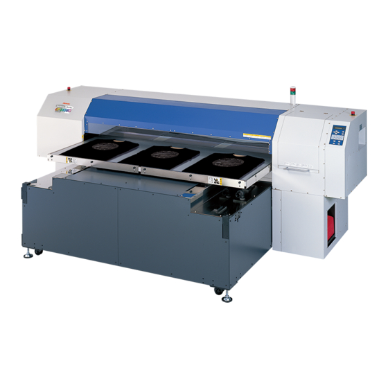
Foreword Congratulations on your purchase of a Garment Printer “GP-1810”. GP-1810 is a flat type, high-speed 4-color inkjet printer for garments and other cloths. Read this Operation Manual carefully and make the most effective use of your printer. • [GP-1810] shifts by a high-speed head. To avoid danger of injury or damage, be sure to read this Operation Manual carefully before start- ing to operate it. -
Page 6: Table Of Contents
Table of contents Foreword ....................i On This Operation Manual ................i Features ....................vi Safety precautions during installation ............ vii Safety symbols used in manual ..............vii Example of pictorials within the manual ............vii Never do the following ................viii Precautions in use .................. - Page 7 Table of contents CHAPTER 2 Basic Operations Operation ..................... 2.2 Switching on the power supply ............2.3 Turning the power on .................2.3 Station cover ..................2.4 Opening/closing the station cover ............. 2.4 Adjusting the head height ..............2.5 Setting the work on the machine ............2.6 Fixing the work holder ................
- Page 8 CHAPTER 4 How to Set Functions Basic operations of menus ..............4.2 Registering a type ................4.4 Changing the type ..................4.4 Setup functions ..................4.5 Change the display language [DISPLAY] ..........4.8 CHAPTER 5 Maintenance Maintenance of the machine ..............5.2 Setting the maintenance function ..............
- Page 9 Table of contents APPENDIX Basic specifications ................A.2 Ink specification ................... A.4 Consumable items ................A.5 Location of safety labels ..............A.6 Function flowchart ................A.9 - v -...
-
Page 10: Features
Features The features of the machine are described below. Together with the method of operation of the machine explained in this manual, they help you understand how to use the machine properly. Use the pigment ink for textile The new pigment ink for textile allows for printing directly T shirt. It allows for the heat treatment (simple post treatment) without media preparation. -
Page 11: Safety Precautions During Installation
Safety precautions during installation Safety symbols used in manual Safety signal words Pictorial signs are used in this Operation Manual for safe operation of and in prevention of damages to the machine. Pictorial signs and their meanings are given below. Read and fully understand before reading the text. -
Page 12: Never Do The Following
Never do the following WARNING Do not disassemble or modify the machine. Power supply and voltage Never disassemble or remodel • Be sure to use the machine with • the main unit of the machine and the power supply specifications the ink cartridge. -
Page 13: Precautions In Use
Safety precautions during installation Precautions in use CAUTION Periodic exchange parts Front cover and lever There are some parts which • • Never open the front cover and/ must be replaced by service or lever during printing. Opening engineer. You have to make a the cover or lever will abort contract with distributors or printing. - Page 14 CAUTION • Using any ink type other than the Ink cartridges exclusive one can cause a • If the ink cartridge is moved from trouble. Remover that the user a cold place to a warm place, do shall be charged for a repair cost not use for three hours.
-
Page 15: Precautions In Installation
Safety precautions during installation Precautions in installation CAUTION A place that is not horizontal A place exposed to direct sunlight Do not place the machine where • Do not install machine where it is • the machine can not be installed exposed to direct sunlight or on a level surface, or you may work may be discolored. -
Page 16: How To Read This Operation Manual
How to read this operation manual Display on the LCD and Indication of the Keys In this Operation Manual, the characters displayed on the LCD of the operation panel and the keys used to operate the machine are explained, together with the operation procedure. page 1.6. -
Page 17: Structure Of This Operation Manual
How to read this operation manual Structure of this Operation Manual This manual consists of the following six chapters to describe the handling of the machine. Chapter 1 Before Use This chapter describes the name and function of each section of the ma- chine as well as ink and work. - Page 18 - xiv -...
- Page 19 CHAPTER 1 Before Use This chapter describes the name and function of each section of the machine as well as ink and work. Table of contents Where to install the machine ..............1.2 Moving the machine ................1.3 Configuration and function ..............1.4 Ink cartridge and Ink station ..............
-
Page 20: Where To Install The Machine
Secure a suitable installation space before assembling the machine. Install the machine considering enough space for the machine size and to perform print operation. Model Width Depth Height Gross weight GP-1810 3070 mm 2210 mm 1350 mm 620 kg or less 1000 mm or more 1000 mm... -
Page 21: Moving The Machine
Moving the machine This section explains to carry the machine to e.g., an instruction location after assembled. Raise the level feet of the table frame before moving the machine to a new location. • Be sure to disconnect the power cable and the interface cable before moving the machine. -
Page 22: Configuration And Function
Configuration and function The Front Name Function Pilot lamp Displays the machine status as ACTIVE (green), or ERROR (red). Station Cover A cover for the station maintenance. Open the cover when performing the station maintenance. EMERGENCY Switch (Emergency) Stop printing. Parallel connector Bi-directional parallel interface connector. -
Page 23: The Rear
Configuration and function The Rear Name Function Ink cartridge Each cartridge contains ink of a specific color. Ink station Set the ink cartridges specified. ( page 1.10) - 1.5 -... -
Page 24: Operation Panel
Operation Panel The operation panel that is used to operate the machine. Display Displays a set item, a guidance error, etc. POWER lamp It lights up (in green) when the power to the machine is turned on. XY keys Z key [ ] [ ] [ ] [ ] Adjust the head (Y bar) height. - Page 25 Configuration and function Functions of the XY keys Each of the keys varies in function according to the time at which it is used. When inputting a choice When setting a When selecting a function selected among several plotting origin / plotting area alternatives Shifts the carriage to the left.
-
Page 26: Capping Station
Capping station The capping station consists of ink caps, wipers for cleaning the heads, etc. : It covers the nozzle so as to prevent the head nozzle from drying up. Wiper : It is used to clean the head nozzle. The wipers are consumable parts. -
Page 27: Ink Cartridge And Ink Station
• Never disassemble the ink cartridge. • The ink cartridge cannot be refilled. Refilling the ink cartridge can cause a trouble. Remember that MIMAKI assumes no responsibility for any damage caused by the use of the ink cartridge replenished with ink. -
Page 28: Ink Station
Ink station The Right ink station supplies ink to the 2 front row of Carriage. The Left ink station supplies ink to the 2 rear row of Carriage. Remember these relationship when checking the heads for clogged nozzles, replacing ink cartridge and replenishing inks. -
Page 29: Types Of Work That Can Be Used
Types of work that can be used The following describes the sizes of work that can be used and the method of handling. Sizes of work that can be used Maximum 1870 mm Minimum 1050 mm Max. printing width 1860 mm Max. -
Page 30: Direct Printing On A Cloth
Direct printing on a cloth • To minimize color variations, maintain constant humidity and tempera- ture while printing directly on a cloth. 1. When using the Pigment ink for textile (TPig ink) • No special preparation is necessary. Print on a dry cloth. •... -
Page 31: Menu Mode
MENU mode The unit’s four modes are described blow. < LOCAL > mode This mode is for the preparatory state. All keys are effective to enable setups. The machine is able to receive data from computer, however, it will not perform printing. In this mode, it is possible to perform the following operations. - Page 32 - 1.14 -...
- Page 33 CHAPTER 2 Basic Operations This chapter describes a series of operations and settings, ranging from power-on to end of printing. Table of contents Operation ....................... 2.2 Switching on the power supply ..............2.3 Station cover ....................2.4 Adjusting the head height ................2.5 Setting the work on the machine ..............
-
Page 34: Operation
Operation The following shows a series of operations and settings, ranging from power-on to end of printing. For details on each item, refer to the reference page. Turn on the power on P. 2.3 Check the head height P. 2.5 Set the work P. -
Page 35: Switching On The Power Supply
BOOT When the power is switched on, the LCD first displays “BOOT” and then displays the firmware version number. GP-1810 V∗.∗∗ 3. The message [Please Wait] appears flushing Please Wait on the LCD. -
Page 36: Station Cover
Station cover Opening/closing the station cover • Keep the station cover closed during printing operation. Opening the station cover during printing interrupts image printing and disables continuous processing. If you open the station cover during printing, the carriage will stop for safety, resulting in abortion of printing. -
Page 37: Adjusting The Head Height
Adjusting the head height The head can be adjusted in height, according to thickness of a work used for printing. The head height must be set according to the work thickness. If the head height is too low, it may affect the printing quality and even damage the work or the machine itself. -
Page 38: Setting The Work On The Machine
Setting the work on the machine Set the work on the table as following. • Adjust the head height before placing a work on the machine. ( page 2.6) • Always print on flat works. • When printing on T-shirts or other cloths, set them flat. STEPS: 1. -
Page 39: Fixing The Work Holder
Setting the work on the machine Fixing the work holder When printing on a material of allowable size (1870 x 1050mm maximum) that tends to bend upward (floating at two or four edges), use the work holders on any of the four table edges to fit the work in place. -
Page 40: Establishing The Origin And The Print Area
Establishing the origin and the print area Initial value The origin and the print area are set as follows by default until they are changed: Effective printing area Work Output direction 15mm Origin - 2.8 -... -
Page 41: Changing The Origin And The Print Area
Establishing the origin and the print area Changing the origin and the print area The default origin and the print area may be changed as needed. • When printing on the entire work surface (without margins), the printing origin and the printing area must be set outside of the work. They must be set as close to the work as possible, however, to minimize smearing the machine itself. -
Page 42: Checking And Solving Nozzle Clogging
Checking and solving nozzle clogging Make test printing to check whether there is nozzle clogging or other printing failures. If the finished test pattern shows any sign of abnormal conditions, carry out the cleaning function. • To perform the test print on a cut sheet medium, use a medium whose size is A4 or larger with placed in landscape configuration. - Page 43 Checking and solving nozzle clogging STEPS: 1. The machine enters the LOCAL mode. << LOCAL >> X =1010 Y = 1860 2. Press the [TEST] key. TEST PRINT < ENT > 3. Press the [TEST] key or [ENTER] key. ∗∗ PRINT ∗∗ The machine prints the test pattern.
- Page 44 10. Press the [ENTER] key. Cleaning 00: ∗ ∗ : ∗ ∗ It displays the remaining run-time. 11. The machine revert the LOCAL mode. << LOCAL >> X =1010 Y = 1860 12. Change the work, or establish the new origin. 13.
-
Page 45: Correcting The Work Feed Rate
Correcting the work feed rate When the work type is changed, the amount of work feed changes. If the correction value is not appropriate, stripes may occur in the printing, disturbing neat printing. Correction for the work feed rate in online is available. ( page 2.15) CORRECTING PATTERN Print two bands. - Page 46 STEPS: 1. The machine enters the LOCAL mode. << LOCAL >> X =1010 Y = 1860 << LOCAL >> 2. Press the [FUNCTION] key. X =1010 Y = 1860 3. Press the [ENTER] key. 4. Press the XY [ ] or [ ] keys to select a type. FUNCTION SELECT : TYPE1...
-
Page 47: Correcting The Media Feed Rate During Printing
Correcting the media feed rate during printing To perform this operation during LOCAL mode, refer to the “Feed Correct”( page 2.13). The following describes the procedures to alter the media feed rate during printing or in a REMOTE mode. STEPS: 1. -
Page 48: Printing An Image From Source Data
Printing an image from source data Starting the printing operation The following describes the method of printing. For various function settings necessary for printing, refer to “CHAPTER4 How to Set Functions”. STEPS: 1. The machine enters the LOCAL mode. << LOCAL >> X =1010 Y = 1860 2. -
Page 49: Interrupting The Printing Operation
Printing an image from source data 4. During the printing. << LOCAL >> X =1010 Y = 1860 5. After the printing operation is completed, put the machine back into the LOCAL mode. The table will move toward you when printing in the Cycle Start mode. -
Page 50: Displaying Machine Information
Displaying machine information Displays the firmware version, ink level etc. This following describes the procedures to display the machine in formation during printing or REMOTE and CYCLE mode. • • • • • In LOCAL mode, information displays by pressing [ENTER] key as well. STEPS: 1. -
Page 51: To Replenish Ink, Set A New Ink Cartridge In The Ink Station
To replenish ink, set a new ink cartridge in the ink station If ink in the cartridge comes to an empty, the corresponding message appears. Printing can be continued but ink may run out during printing. Immediately put a new ink cartridge. <... -
Page 52: Turning The Power Off
Turning the power off To turn the power off, check first whether there is data in the machine that remains to be printed. Also make sure that the head rests at the capping station. • If the power is turned off while the machine is engaged in printing, the head may fail to be retracted in the capping station. - Page 53 CHAPTER 3 Daily Care This chapter describes daily cleaning. Table of contents Routine maintenance ................3.2 Cleaning the wiper and ink caps ............3.4 Cleaning the nozzle [Nozzle Cleaning] ..........3.7 Replacing the flushing tray ink absorber ..........3.10 When the waste ink tank becomes full ..........3.12 Ink discharge way cleaning [Drain Wash] ..........
-
Page 54: Routine Maintenance
Routine maintenance Be sure to conduct maintenance works for the machine when necessary or periodically so as to use the machine for a long time while keeping its printing accuracy. When the machine is left unused for a long period of time •... -
Page 55: Maintenance For Frame Components
Routine maintenance Maintenance for frame components If the frame components of the machine have become dirty, wipe off frame with soft cloth using water or neutral detergent diluted with water, squeeze it and wipe the frame components clean. Clean the table also as dust may cause ink fly-bend or dropping. Cleaning Tools : •... -
Page 56: Cleaning The Wiper And Ink Caps
Cleaning the wiper and ink caps The ink cap prevents clogging of the head nozzle caused by dried nozzle. The wiper wipes out ink adhered to the head nozzle. As the machine is used to print images, the wipers and ink caps gradually become stained with ink and dust. - Page 57 Cleaning the wiper and ink caps FUNCTION 2. Press the XY [ ] or [ ] keys to select [MAINTE- MAINTENANCE < ENT > NANCE]. MAINTENANCE 3. Press the [ENTER] key. List < ent > MAINTENANCE 4. Press the XY [ ] or [ ] keys to select [Station]. Station <...
- Page 58 7. Clean the wiper guide shaft using a cotton swab of cloth. If dirt is hard to remove, use a cotton swab of cloth damp- ened with water. • Extremely dirty wiper guide shaft may cause operationed failure of the wiper, resulting in error display.
-
Page 59: Cleaning The Nozzle [Nozzle Cleaning]
Cleaning the nozzle [Nozzle Cleaning] Clean up the nozzle as for nozzle clogging. If nozzle clogging cannot be resolved even after cleaning several times, execute the [Ink Filling] function. ( page 5.11) If this error cannot be resolved with these functions, contact the dealer. •... - Page 60 6. Open the station cover. Don’t rub. Use and push a cotton swab contained clean- ing liquid (A29) to take off some dust on the felt surface. Felt surface Use a cotton swab contained cleaning liquid (A29) to take off some inks on the rubber sur- face.
- Page 61 Cleaning the nozzle [Nozzle Cleaning] Nozzle Cleaning 10. Press the XY [ ] or [ ] keys, select the time to Wait Timer = 1 min leave. (1-99 minutes: 1 min unit) Normally set 1 min. Initialize 11. Press the [ENTER] key. Please Wait The initial operation is performed.
-
Page 62: Replacing The Flushing Tray Ink Absorber
Replacing the flushing tray ink absorber Replace the ink absorber in the flushing tray if it appears to be clogged. Clogged ink absorber may cause ink mists and smeared head nozzles. In addition, ink bounce causes some ink drips on the nozzle during flushing. Some ink drips may cause some trouble on ink firing. - Page 63 Replacing the flushing tray ink absorber F-cover upward 7. Remove the F-cover upward from the flushing tray. 8. Remove the ink absorber. 9. Place a new ink absorber (supplied) on the tray. Place the ink absorber (as folded) at the center. Ink absorber •...
-
Page 64: When The Waste Ink Tank Becomes Full
Waste Ink Tank Ink Tank Is Full Ink Tank Near Full • Contact your local MIMAKI distributor or call a local MIMAKI office if you need a spare waste ink tank. • Prepare a polyethylene tank for emptying waste ink. -
Page 65: Ink Discharge Way Cleaning [Drain Wash]
Ink discharge way cleaning [Drain Wash] The ink discharge way may become clogged by coagulated ink. It must be cleaned at regular inter- vals to avoid clogging. Ink discharge way: Tubing between the cap and the waste ink tank • Do not move the carriage out of the capping station by hand. Use the appropriate operation key to move the carriage. - Page 66 7. Open the station cover. 8. Remove the cleaning liquid (A29) with a sy- ringe. During the suction pause period, drop the cleaning liquid (A29) until just before it overflows from the cap. 9. Close the front cover, and press the [ENTER] Drain Wash Completed : ent...
-
Page 67: When Not In Use The Machine Over The Long Term [Storage Wash]
When not in use the machine over the long term [Storage Wash] When not in use the machine over a week, perform [Storage Wash] function to clean the head nozzle and ink discharge way. After performing the function, store the machine. •... - Page 68 8. Take off the wiper with holding projections at the tips of wiper. 9. Use a cotton swab soaked with the cleaning liquid (A29) to clean off ink blots on wiper and bracket. • If dirt of curl is serious, replace the wiper with a new one.
-
Page 69: When Not In Use The Machine Over The Long Term [Storage Wash
When not in use the machine over the long term [Storage Wash] Fill Up Washings 13. Close the station cover, and press the [ENTER] Completed : ent key. Nozzle Cleaning 14. Press the JOG [ ] or [ ] keys, select the time Wait Timer = 1 min to leave. - Page 70 17. Clean the wiper and press the [ENTER] key. Wiper Cleaning Completed : ent 18. Clean the wiper guide shaft using a cotton swab of cloth. If dirt is hard to remove, use a cotton swab of cloth damp- ened with water. •...
- Page 71 CHAPTER 4 How to Set Functions This chapter describes how to set up the machine. Table of contents Basic operations of menus ................4.2 Registering a type ..................4.4 Setup functions....................4.5 Change the display language [DISPLAY] ............4.8 - 4.1 -...
-
Page 72: Basic Operations Of Menus
Basic operations of menus This section describes how to change over the operation modes and how to operate the menus. The following gives the key operation flow to invoke menus. For detailed menu configuration, refer to Appendix. REMOTE << LOCAL >> <... - Page 73 Basic operations of menus 1. Select the LOCAL mode. Ascertain first that the machine does not perform printing under the REMOTE mode, then press the [REMOTE] key to enter the LOCAL mode. 2. Select the FUNCTION mode. Press the [FUNCTION] key, and the machine will enter the FUNCTION mode. The FUNCTION mode is divided into two: the setup function and maintenance function.
-
Page 74: Registering A Type
Registering a type The FUNCTION mode enable to regists 4 types. If the type has been registered for each medium type, it becomes easy to change plotting conditions when the medium type is changed. STEPS: 1. Make sure that the mode is LOCAL mode. <<... -
Page 75: Setup Functions
Setup functions The FUNCTION mode consists of 14 items. The following describes the overview of and settings for each function. Print Mode Sets the print quality, print direction. Quality : Select the quality image from three items. [STD] Standard image quality [FINE] High image quality and low printing speed [High SPD] :... - Page 76 Priority Specifies whether the values set on the machine (print) are given priority or the values set on the computer (host) are enabled as for the following five functions. • Print Mode • Overprint • Drying Time • Feed Correct •...
- Page 77 Setup functions Auto Clean The head is cleaned automatically. Perform cleaning for each print to prevent printing failures. [ON] : The head is cleaned automatically. [OFF] : The head is not cleaned automatically. Setup Reset This function resets the current printing conditions to the factory-set printing conditions. Execute this function for each of the types of set printing conditions.
-
Page 78: Change The Display Language [Display]
Change the display language [DISPLAY] Display language enable to change Japanese or English. This procedure explains how to change Display language to ENGLISH. STEPS: << LOCAL >> 1. Make sure that the mode is LOCAL mode. X =1010 Y = 1860 FUNCTION 2. - Page 79 CHAPTER 5 Maintenance In order to keep the machine in good operating condition, it is necessary to carry out maintenance of the machine periodically. This chapter introduces special features for correcting poor printing quality and replacing the wipers. Table of contents Maintenance of the machine ..............
-
Page 80: Maintenance Of The Machine
Maintenance of the machine The term “maintenance” as used herein refers to actions that need to be taken to keep the machine in good operating condition. To carry out maintenance of the machine, select [MAINTENANCE] from the function menu and make the necessary settings. -
Page 81: Maintenance Setup Functions
Maintenance of the machine Maintenance setup functions The following describes the overview of and settings for each function. Name function List Printing the set condition of the machine. page 5.4 page 5.5 Data Dump Printing data commands received from the computer, in HEX code. page 5.6 Print Adjust Adjust the dot position according to the head height, high/low. -
Page 82: Printing Setup Conditions [List]
Printing setup conditions [LIST] This function lists the current settings of the machine. This is useful in carrying out maintenance of the machine. SET UP : Indicates a value that is specified with the FUNCTION. PRINT adjust : Indicates a correction value for dot position. REPLACE COUNTER : Indicates the number of times the ink cartridges are replaced. -
Page 83: Printing Hex Code [Data Dump]
Printing HEX CODE [DATA DUMP] This function prints data commands received from the computer, in HEX code. The HEX code is an alphanumeric representation of printing commands. By using this code, it is possible to check if there are any abnormal data commands. •... -
Page 84: When Medium Thickness Is Changed [Print Adjust]
When medium thickness is changed [Print Adjust] When the head height is adjusted, be sure to correct the dot positions. This function corrects the dot positions to ensure that the accurate printing result is obtained. The dot positions are corrected by comparing the ink dropping positions on each of the seven test patterns between the two printing directions. - Page 85 When medium thickness is changed [Print Adjust] 6. Press the [ENTER] key. Print Adjust Pattern2 = 0.0 Print Adjust Pattern3 = 0.0 7. Repeat STEPS 5 and 6 to correct the dot posi- tions on Patterns 2 to 7. Print Adjust Pattern4 = 0.0 Select the correct dot positions on each of the patterns.
-
Page 86: Cleaning The Station Interior [Station]-[Carriage Out]
Cleaning the station interior [Station]-[Carriage Out] Move the carriage when cleaning the station interior and replacing the consumable parts. • Do not move the carriage out of the capping station by hand. Use the appropriate operation key to move the carriage. STEPS: 1. -
Page 87: When The Message [Replace Wiper] Is Displayed [Station]-[Wiper Exchng]
When the message [Replace Wiper] is displayed [Station]- [Wiper Exchng] The wipers are consumable parts. When the following message is displayed, replace the wipers with new ones. Wiper Replace Wiper • Do not press the [ENTER] key other than the case of replacing wipers. The number of wiper operations that is counted in the machine will be reset. - Page 88 7. Holding the projections at both ends, insert a new wiper into place. • Contacting the rubber portion of a new wiper shall be avoided. It can cause the nozzle to be clogged. • Insert the wiper so that its felt side surface is placed on the left as viewed from your position.
-
Page 89: Fill Up The Ink [Ink Filling]
Fill up the ink [Ink Filling] Perform the [Storage Wash] function for nozzle clogging when head cleaning or [Nozzle cleaning] does not work. In addition, when the [Nozzle cleaning] function or the [Storage Wash] function is performed, this may cause color mixture. Perform the [Ink Filling] function to discharge mixed color ink. -
Page 90: Charging Ink Different From The One In Use [Ink Change]
• Be sure to use the inks and ink cartridges specified by MIMAKI. Please be noted that MIMAKI shall have no liability for any trouble that arises when using any ink cartridge or ink other than the genuine MIMAKI brand ones. - Page 91 Charging ink different from the one in use [Ink Change] 9. Install the washing liquid cartridge. Set Washing Liq. 1 2 5 6 3 4 7 8 ABEFCDGH Load the washing liquid cartridge at the position of the ink discharged in step 8. Washing is started automatically. Washing 00: ∗∗...
-
Page 92: Displaying The Firmware Version [Information]
Displaying the firmware version [INFORMATION] Display the firmware versions of this machines and an interface. If trouble occurs, please inform the dealer or MIMAKI sales office of the contents of the trouble as well as this information. STEPS: 1. Make sure that the FUNCTION mode is dis- FUNCTION played. -
Page 93: Specifying The Print Head Line [Use Head]
Specifying the print head line [Use Head] Use this function if nozzle missing cannot be recovered even after repetitive cleaning or if plotting with higher quality is required. Divide the 16 (4x4) nozzles in the carriage into four horizontal rows to specify the print headline. -
Page 94: Execute The Flushing And Cleaning Regularly [Routine Control]
Execute the flushing and cleaning regularly [Routine Control] This function allows for the pigment ink for textile (TPig). Set time limits on the flushing and cleaning functions at regular time intervals to avoid nozzle clogging and clean off dust on the nozzle surface. Routine Flushing The routine flushing function is executed with the power on. - Page 95 Execute the flushing and cleaning regularly [Routine Control] Routine Cleaning The routine cleaning function is executed with the power on. Time set by the hour is available for 1 to 48 hrs with this function turns on. STEPS: 1. Make sure that the FUNCTION mode is dis- FUNCTION played.
- Page 96 - 5.18 -...
- Page 97 CHAPTER 6 When Abnormal Conditions Are Encountered Chapter 6 describes corrective measures to be taken in the case where an to be taken in case an abnormal condition arises and an error message appears on the display. Table of contents Abnormal conditions where no error massage appears ......
-
Page 98: Abnormal Conditions Where No Error Massage Appears
Corrective measures for problems where no error message is given on the LCD are described in this section. Be sure to take the following measures before contacting MIMAKI. If the measures fail to fix the machine, contact your local MIMAKI distributor or MIMAKI office for service. -
Page 99: If Image Quality Declines
Corrective measures against problems where satisfactory image quality is not provided are described in this station. Take measures in accordance with actual state of the picture. If the measures fail fix the machine, contact your local MIMAKI distributor or MIMAKI office call for service. -
Page 100: Problems Where Error Messages Are Given On The Lcd
Problems where error messages are given on the LCD If something is wrong with the machine, the buzzer sounds and a corresponding error message is given on the LCD. Take an appropriate corrective measure in accordance with the message. Errors accompanied by warnings These errors arise on the ink-related components. - Page 101 Warning message Cause Corrective measure The loaded ink cartridge is not Use the ink specified by MIMAKI. Unidentified Ink 1 2 3 4 5 6 7 8 A B C D E F G H MIMAKI genuine. The ink cartridge will expire...
- Page 102 Warning message Cause Corrective measure Temperature is below operable Adjust environmental temperature. Below Operable Temperature condition. Temperature is below guaran- Temperature Evn. Temp is Low teed. Temperature is over below Temperature guaranteed. Evn. Temp is High - 6.6 -...
-
Page 103: Error Messages
If any error message is given on the LCD, turn off the power to the machine for while and turn it back on. If the same error message appears again on the LCD, contact your local MIMAKI distributor or MIMAKI office to call for service. - Page 104 Warning message Cause Corrective measure A parameter outside the range of Check the host computer output ERROR 11 acceptable numeric values is setting. PARAMETER received. Strange color data has been ERROR 14 COLOR COMMAND received. Improper operation has been Turn off the power to the machine ERROR 20 conducted on the operation panel.
- Page 105 Problems where error messages are given on the LCD Warning message Cause Corrective measure ERROR 46 The wiper position is not Turn off the power to the machine WIPER correct. for a while and then turn it on. If the same error message appears Origin could not be detected.
- Page 106 - 6.10 -...
-
Page 107: Appendix
APPENDIX This appendix describes the specifications of the machine and components and the structure of the function menu. Table of contents Basic specifications ................A.2 Ink specification ................... A.4 Consumable items ................A.5 Location of safety labels ..............A.6 Function flowchart ................A.9 - A.1 -... -
Page 108: Basic Specifications
360 x 720 dpi : 4 / 8 / 16 passes, Unidirection / bidirection 720 x 720 dpi : 4 / 8 / 16 passes, Unidirection / bidirection Usable ink Pigment Ink for Textile (MIMAKI original ink) Acid Dye Ink (MIMAKI original ink) Reactive Dye Ink (MIMAKI original ink) -
Page 109: Specifications
Basic specifications Item GP-1810 Power AC 200 – 240 V± 10% ( Auto voltage ), 50/60 Hz ± 1 Hz Power consumption 500VA Recomended Available temp. 15 °C – 30 °C Environment Humidity 40 – 65 % Rh (No condensation) Guaranteed temp. -
Page 110: Ink Specification
Ink specification Item Specifications Form Exclusive ink cartridge Type Pigment ink for Textile / SPC-0350 series (K, M, C, Y) Acid dye ink / SPC-0355 series (K, M, C, Y) Disperse dye ink / SPC-0356 series (K, M, C, Y) Reactive dye ink / SPC-0357 series (K, M, C, Y) Contents of ink 210 to 220 cc per cartridge... -
Page 111: Consumable Items
Consumable items Consumable items listed below must be renewed at regular intervals to maintain adequate printing quality. Contact your local MIMAKI distributor or call a local MIMAKI office for services. Wiper 4pcs : Order No. SPA-0105 Ink absorber for the flushing tray 100pcs : Order No. -
Page 112: Location Of Safety Labels
The following safety labels (10 kinds and 15 labels in total) have been attached to this machine. If any of them fall off or become illegible, contact MIMAKI local distributor for a replacement. All persons who install, operate and maintain this machine should understand and follow the safety precautions in these labels. - Page 113 Location of safety labels Order No. Label M903968 LHDM-04 (Japanese) PED-04 (English) M901469 M901607 M901549 M903226 (Japanese) M904325 (English) LHCM-02 (Japanese) PEC-02 (English) - A.7 -...
- Page 114 - A.8 -...
-
Page 115: Function Flowchart
Function flowchart - A.9 -... - Page 116 BOOT GP-1810 V ∗ . ∗ ∗ Move up Z Move the table forward and discharge X origin ENTER ENTER Please Wait Ink Cartridge Ink Type --------ABCDEFGH Type :TPig No ink cartridge V) : Acid,Reac,Disp << LOCAL >> X= ∗ ∗ ∗ ∗...
- Page 117 Function Flowchart Filling 00:00:00 Display remaining time - A.11 -...
- Page 118 1 2 3 4 5 6 7 8 9 0 1 2 3 4 5 6 7 8 9 0 1 2 3 4 5 1 2 3 4 5 6 7 8 9 0 1 2 3 4 5 6 7 8 9 0 1 2 3 4 5 1 2 3 4 5 6 7 8 9 0 1 2 3 4 5 6 7 8 9 0 1 2 3 4 5 1 2 3 4 5 6 7 8 9 0 1 2 3 4 5 6 7 8 9 0 1 2 3 4 5 1 2 3 4 5 6 7 8 9 0 1 2 3 4 5 6 7 8 9 0 1 2 3 4 5...
- Page 119 Function Flowchart ENTER ENTER Print Area Print Area Print Area end< >ent X=∗ ∗ ∗ ∗ Y=∗ ∗ ∗ ∗ X=∗ ∗ ∗ ∗ Y=∗ ∗ ∗ ∗ < >):JOG MODE 1 2 3 4 5 6 7 8 9 0 1 2 3 4 5 6 7 8 9 0 1 2 3 4 5 6 1 2 3 4 5 6 7 8 9 0 1 2 3 4 5 6 7 8 9 0 1 2 3 4 5 1 2 3 4 5 6 7 8 9 0 1 2 3 4 5 6 7 8 9 0 1 2 3 4 5 6 1 2 3 4 5 6 7 8 9 0 1 2 3 4 5 6 7 8 9 0 1 2 3 4 5...
- Page 120 1 2 3 4 5 6 7 8 9 0 1 2 3 4 5 6 7 8 9 0 1 2 3 4 5 1 2 3 4 5 6 7 8 9 0 1 2 3 4 5 6 7 8 9 0 1 2 3 4 5 1 2 3 4 5 6 7 8 9 0 1 2 3 4 5 6 7 8 9 0 1 2 3 4 5 1 2 3 4 5 6 7 8 9 0 1 2 3 4 5 6 7 8 9 0 1 2 3 4 5 1 2 3 4 5 6 7 8 9 0 1 2 3 4 5 6 7 8 9 0 1 2 3 4 5...
- Page 121 Function Flowchart Cleaning Cleaning 00:00:00 Please Wait Display remaining time 1 2 3 4 5 6 7 8 9 0 1 2 3 4 5 6 7 8 9 0 1 2 3 4 5 6 7 8 1 2 3 4 5 6 7 8 9 0 1 2 3 4 5 6 7 8 9 0 1 2 3 4 5 6 7 8 Display when Ink Near End occurs 1 2 3 4 5 6 7 8 9 0 1 2 3 4 5 6 7 8 9 0 1 2 3 4 5 6 7 8 1 2 3 4 5 6 7 8 9 0 1 2 3 4 5 6 7 8 9 0 1 2 3 4 5 6 7 8...
- Page 122 1 2 3 4 5 6 7 8 9 0 1 2 3 4 5 6 7 8 9 0 1 2 3 4 5 1 2 3 4 5 6 7 8 9 0 1 2 3 4 5 6 7 8 9 0 1 2 3 4 5 1 2 3 4 5 6 7 8 9 0 1 2 3 4 5 6 7 8 9 0 1 2 3 4 5 1 2 3 4 5 6 7 8 9 0 1 2 3 4 5 6 7 8 9 0 1 2 3 4 5 1 2 3 4 5 6 7 8 9 0 1 2 3 4 5 6 7 8 9 0 1 2 3 4 5...
- Page 123 Function Flowchart 1 2 3 4 5 6 7 8 9 0 1 2 3 4 1 2 3 4 5 6 7 8 9 0 1 2 3 4 1 2 3 4 5 6 7 8 9 0 1 2 3 4 If FUNC key 1 2 3 4 5 6 7 8 9 0 1 2 3 4 ENTER...
- Page 124 1 2 3 4 5 6 7 8 9 0 1 2 3 4 5 6 7 8 9 0 1 2 3 4 5 1 2 3 4 5 6 7 8 9 0 1 2 3 4 5 6 7 8 9 0 1 2 3 4 5 1 2 3 4 5 6 7 8 9 0 1 2 3 4 5 6 7 8 9 0 1 2 3 4 5 1 2 3 4 5 6 7 8 9 0 1 2 3 4 5 6 7 8 9 0 1 2 3 4 5 1 2 3 4 5 6 7 8 9 0 1 2 3 4 5 6 7 8 9 0 1 2 3 4 5...
- Page 125 Function Flowchart ENTER ENTER TYPE TYPE TYPE ∗ ∗ ∗ Quality :STD Direction :UNI-D ReturnSpd:NORMAL ):FINE ):BI-D :SLOW :HighSPD TYPE ∗ Layer :1~9 TYPE ∗ Time :0.0s )=0.0~9.9s TYPE ENTER TYPE ENTER TYPE ∗ ∗ ∗ PrintMode :HOST Ink Layers :HOST :HOST ):PLOT...
- Page 126 1 2 3 4 5 6 7 8 9 0 1 2 3 4 5 6 7 8 9 0 1 2 3 4 5 1 2 3 4 5 6 7 8 9 0 1 2 3 4 5 6 7 8 9 0 1 2 3 4 5 1 2 3 4 5 6 7 8 9 0 1 2 3 4 5 6 7 8 9 0 1 2 3 4 5 1 2 3 4 5 6 7 8 9 0 1 2 3 4 5 6 7 8 9 0 1 2 3 4 5 1 2 3 4 5 6 7 8 9 0 1 2 3 4 5 6 7 8 9 0 1 2 3 4 5...
- Page 127 Function Flowchart TYPE ∗ Refresh :Level3 ):Level0~Level3 TYPE ∗ mm/inch ) :inch - A.21 -...
- Page 128 1 2 3 4 5 6 7 8 9 0 1 2 3 4 5 6 7 8 9 0 1 2 3 4 5 1 2 3 4 5 6 7 8 9 0 1 2 3 4 5 6 7 8 9 0 1 2 3 4 5 1 2 3 4 5 6 7 8 9 0 1 2 3 4 5 6 7 8 9 0 1 2 3 4 5 1 2 3 4 5 6 7 8 9 0 1 2 3 4 5 6 7 8 9 0 1 2 3 4 5 1 2 3 4 5 6 7 8 9 0 1 2 3 4 5 6 7 8 9 0 1 2 3 4 5...
- Page 129 Function Flowchart 1 2 3 4 5 6 7 8 9 0 1 2 3 1 2 3 4 5 6 7 8 9 0 1 2 3 1 2 3 4 5 6 7 8 9 0 1 2 3 Output 1 2 3 4 5 6 7 8 9 0 1 2 3 ENTER...
- Page 130 1 2 3 4 5 6 7 8 9 0 1 2 3 4 5 6 7 8 9 0 1 2 3 4 5 1 2 3 4 5 6 7 8 9 0 1 2 3 4 5 6 7 8 9 0 1 2 3 4 5 1 2 3 4 5 6 7 8 9 0 1 2 3 4 5 6 7 8 9 0 1 2 3 4 5 1 2 3 4 5 6 7 8 9 0 1 2 3 4 5 6 7 8 9 0 1 2 3 4 5 1 2 3 4 5 6 7 8 9 0 1 2 3 4 5 6 7 8 9 0 1 2 3 4 5...
- Page 131 Function Flowchart Printing ∗∗ ∗∗ Please Wait 1 2 3 4 5 6 7 8 9 0 1 2 3 4 5 1 2 3 4 5 6 7 8 9 0 1 2 3 4 5 Receiving Data 1 2 3 4 5 6 7 8 9 0 1 2 3 4 5 1 2 3 4 5 6 7 8 9 0 1 2 3 4 5 Dumping ∗∗...
- Page 132 1 2 3 4 5 6 7 8 9 0 1 2 3 4 5 6 7 8 9 0 1 2 3 4 5 1 2 3 4 5 6 7 8 9 0 1 2 3 4 5 6 7 8 9 0 1 2 3 4 5 1 2 3 4 5 6 7 8 9 0 1 2 3 4 5 6 7 8 9 0 1 2 3 4 5 1 2 3 4 5 6 7 8 9 0 1 2 3 4 5 6 7 8 9 0 1 2 3 4 5 1 2 3 4 5 6 7 8 9 0 1 2 3 4 5 6 7 8 9 0 1 2 3 4 5...
- Page 133 Function Flowchart 1 2 3 4 5 6 7 8 9 0 1 2 3 4 5 6 7 8 9 0 1 2 3 4 5 6 1 2 3 4 5 6 7 8 9 0 1 2 3 4 5 6 7 8 9 0 1 2 3 4 5 6 Carriage Out ENTER Initialize...
- Page 134 1 2 3 4 5 6 7 8 9 0 1 2 3 4 5 6 7 8 9 0 1 2 3 4 5 1 2 3 4 5 6 7 8 9 0 1 2 3 4 5 6 7 8 9 0 1 2 3 4 5 1 2 3 4 5 6 7 8 9 0 1 2 3 4 5 6 7 8 9 0 1 2 3 4 5 1 2 3 4 5 6 7 8 9 0 1 2 3 4 5 6 7 8 9 0 1 2 3 4 5 1 2 3 4 5 6 7 8 9 0 1 2 3 4 5 6 7 8 9 0 1 2 3 4 5...
- Page 135 Function Flowchart 1 2 3 4 5 6 7 8 9 0 1 2 3 4 5 6 7 8 9 0 1 2 3 4 5 6 7 8 9 0 1 2 3 4 5 6 7 8 9 0 1 2 3 4 5 6 7 8 9 0 1 2 3 4 5 6 7 8 9 0 ENTER Drain Wash Initialize...
- Page 136 1 2 3 4 5 6 7 8 9 0 1 2 3 4 5 6 7 8 9 0 1 2 3 4 5 1 2 3 4 5 6 7 8 9 0 1 2 3 4 5 6 7 8 9 0 1 2 3 4 5 1 2 3 4 5 6 7 8 9 0 1 2 3 4 5 6 7 8 9 0 1 2 3 4 5 1 2 3 4 5 6 7 8 9 0 1 2 3 4 5 6 7 8 9 0 1 2 3 4 5 1 2 3 4 5 6 7 8 9 0 1 2 3 4 5 6 7 8 9 0 1 2 3 4 5...
- Page 137 Function Flowchart Filling Filling 00:00:00 Please Wait Shows remaining times Status Proc Remove Cartridge Washing Set Washing Liq. verify 12345678ABCDEFGH 00:00:00 12345678ABCDEFGH Remove ink cartridge Discharge Ink Set washing tools Status verify Status Proc Remove Washing Washing Set Washing Liq. verify 12345678ABCDEFGH 00:00:00...
- Page 138 1 2 3 4 5 6 7 8 9 0 1 2 3 4 5 6 7 8 9 0 1 2 3 4 5 1 2 3 4 5 6 7 8 9 0 1 2 3 4 5 6 7 8 9 0 1 2 3 4 5 1 2 3 4 5 6 7 8 9 0 1 2 3 4 5 6 7 8 9 0 1 2 3 4 5 1 2 3 4 5 6 7 8 9 0 1 2 3 4 5 6 7 8 9 0 1 2 3 4 5 1 2 3 4 5 6 7 8 9 0 1 2 3 4 5 6 7 8 9 0 1 2 3 4 5...
- Page 139 Function Flowchart Routine Flushing Routine Flushing ENTER Flushing Interval :OFF :1–24h Routine Cleaning Routine Cleaning ENTER Cleaning Interval :OFF :1–48h Use Head InkType :TPig ):Acid Reac Disp - A.33 -...
- Page 140 1 2 3 4 5 6 7 8 9 0 1 2 3 4 5 6 7 8 9 0 1 2 3 4 5 1 2 3 4 5 6 7 8 9 0 1 2 3 4 5 6 7 8 9 0 1 2 3 4 5 1 2 3 4 5 6 7 8 9 0 1 2 3 4 5 6 7 8 9 0 1 2 3 4 5 DISP 1 2 3 4 5 6 7 8 9 0 1 2 3 4 5 6 7 8 9 0 1 2 3 4 5...
- Page 142 Printed in Japan © MIMAKI ENGINEERING Co., Ltd.
Need help?
Do you have a question about the GP-1810 and is the answer not in the manual?
Questions and answers