
Subscribe to Our Youtube Channel
Related Manuals for MIMAKI SWJ-320 S2


Summary of Contents for MIMAKI SWJ-320 S2
- Page 1 MIMAKI ENGINEERING CO., LTD. URL: http://eng.mimaki.co.jp/ D202342-16 Original instructions...
-
Page 2: Table Of Contents
TABLE OF CONTENS CAUTION ................v DISCLAIMER OF WARRANTY ........v Requests ................v FCC Statement (USA) ............. v Foreword ................vi About usable ink ............. vi On This Operation manual ..........vi Safety Precautions .............. vii Symbols ................. vii Pay attention to the electric shock ........x Pay attention to the pinching or catching ...... - Page 3 Adjusting the Head Height ..........2-14 Setting the printing area ..........2-17 Setting leaf media ............2-18 Changing the printing origin ..........2-19 Preparing for the Heaters ..........2-20 Setting the heater ............2-20 Setting the adsorption fan ..........2-21 Setting the drying fan ............2-22 If ruck is generated on the printing surface of the media ................2-22 Test Printing ..............
- Page 4 Displaying the Information ..........3-22 Displaying the Information of this machine .....3-23 Chapter 4 Maintenance Maintenance ..............4-2 Precautions for Maintenance ..........4-2 About Cleaning Solution ...........4-2 Cleaning the Exterior Surfaces .........4-3 Cleaning the Platen ............4-3 Cleaning of after heater cover and pre heater cover ..4-3 Cleaning the Media Holder ..........4-4 Maintaining the Capping Station ........
- Page 5 Chapter 6 Appendix Specifications ..............6-2 Machine specifications ............6-2 Ink specifications ..............6-3 Warning labels ..............6-4 Sheet for inquiry ..............6-6 Function Flowchart ............6-8...
-
Page 6: Caution
CAUTION DISCLAIMER OF WARRANTY THIS LIMITED WARRANTY OF MIMAKI SHALL BE THE SOLE AND EXCLUSIVE WARRANTY AND IS IN LIEU OF ALL OTHER WARRANTIES, EXPRESS OR IMPLIED, INCLUDING, BUT NOT LIMITED TO, ANY IMPLIED WARRANTY OF MERCHANTABILITY OR FITNESS, AND MIMAKI NEITHER ASSUMES NOR... -
Page 7: Foreword
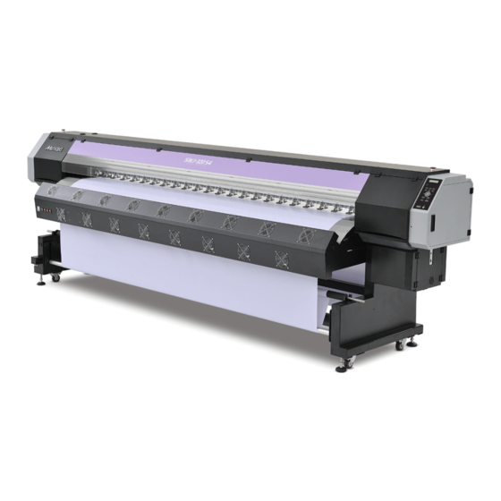
Foreword Congratulations on your purchase of MIMAKI color ink jet printer "SWJ-320S" . “SWJ-320S” is a color inkjet printer that can print on 3.2m-width media (tarpaulin/FF/polyvinyl chloride film) with solvent ink realizing high image quality. About usable ink Usable ink for this machine is CS ink (four-color model). -
Page 8: Safety Precautions
Safety Precautions Symbols Symbols are used in this Operation Manual for safe operation and for prevention of damage to the machine. The indicated sign is different depending on the content of caution. Symbols and their meanings are given below. Please follow these instructions as you read this manual. Examples of symbols Meaning Failure to observe the instructions given with this symbol can result in death or serious injuries... -
Page 9: Warning For Use
Check first that the machine no longer produces smoke, and then contact your distributor or a sales office of MIMAKI for repair. • Never repair your machine by yourself since it is very dangerous for you to do so. -
Page 10: Cautions And Notes
• The machine does not operate with any ink other than the Handling of media SWJ-320S genuine ink. • Use media recommended by MIMAKI to ensure reliable, • Do not use the SWJ-320S genuine ink with other printers, high-quality printing. -
Page 11: Pay Attention To The Electric Shock
Safety Precautions Cautions on Installation CAUTION A place exposed to direct A place where temperature or On an inclined surface sunlight humidity varies significantly • Use the machine under the following environmental conditions: • Operating environment: 20 to 35 °C (68 to 95 °F) 35 to 65 % (Rh) A place exposed to direct air... -
Page 12: Pay Attention To The Pinching Or Catching
Safety Precautions Pay attention to the pinching or catching ① Note the pinching It may cause to pinch fingers or hands by suddenly closing of cover. ② Note the catching Keep hands or hair a distance from the driving parts during the operation of this product. It may suffer an injury by pinching hands or twining hair. -
Page 13: Before Use
Chapter 1 Before Use This chapter describes the items required to understand before use, such as the name of each part of the machine or the installation procedures. Moving This Machine ........1-2 Connecting Cables ........1-9 Where to Install This Machine ..... 1-2 Connecting USB2.0 Interface Cable ....1-9 Working Environmental Temperature .. -
Page 14: Moving This Machine
Moving This Machine Where to Install This Machine Secure a suitable installation space before assembling this machine. The place of installation must have enough space for not only this machine itself, but also for the printing operation. Width Depth Height Gross weight 4560 mm 1200 mm... -
Page 15: Moving This Machine
Moving This Machine Moving This Machine Move this machine according to the following steps when this machine needs to be moved on the same step- free floor. • When the machine is moved to any place other than on the same step-free floor, contact your distributor or our service office. -
Page 16: Names Of Parts And Functions
Names of Parts and Functions Front Side of the Machine Left maintenance cover Open the cover in maintenance. Even when the power switch is off, keep all covers closed. Platen The printed media is sent out, sliding on the platen. Three heaters are installed inside the platen. Print heater/ Post-heater Fixes and dries the ink on the currently produced print. -
Page 17: Rear Side And Right Side Of The Machine
Names of Parts and Functions Rear Side and Right Side of the Machine Main power switch Turns on/off the main power for this machine. Leave the main power turned on to prevent ink clogging. Main power switch AC inlet Connect the power cable to the AC inlet. AC inlet of the heater Connect the power cable to the AC inlet. -
Page 18: Operation Panel
Operation Panel Use the operation panel to make settings for printing or operate this machine. Display Displays the status of the Carry out the print area reset and the head height machine, set items and errors. adjustment function. ACTIVE lamp Prints test patterns to check whether there are print failures such as ink clogging. -
Page 19: Heater
Names of Parts and Functions Heater Pre-heater/Print heater/Post-heater are equipped on the platen. The Pre-heater is used for pre-heating of the media prior to printing to prevent rapid changes in temperature. The Print-heater improves the image quality in printing.The Post-heater and drying-heater dries ink after printing. -
Page 20: Capping Station
Names of Parts and Functions Capping station • Be sure to wear the attached goggles in cleaning within the capping station to protect your eyes against ink. Otherwise, you may get ink in your eyes. The capping station consists of the ink caps, the wiper for cleaning the heads, etc. -
Page 21: Connecting Cables
Connecting Cables Connecting USB2.0 Interface Cable Connect the PC and this machine with the USB2.0 interface cable. USB cable • Your RIP must be compatible with USB 2.0. • Contact a RIP maker near your location or our office when the USB2.0 interface is not attached to the PC. -
Page 22: Connecting The Power Cable
Connecting Cables Removing USB memory If a USB memory module is inserted in the personal computer to which a SWJ-320S machine is connected, click "Stop" in the "Safely Remove Hardware" window by following the instructions given there first and then remove the module. -
Page 23: Ink Bottle Replacement And Charging
Ink bottle replacement and charging This unit manages the use-by date and the amount of ink remaining by reading the information of ink IC chip attached on the ink bottle. Replace the ink bottle, according to the following procedures. Replace the inkbottle. (1) Remove the bottle cap. -
Page 24: Caution In Handling Of Ink Bottles
• Do not shake ink bottles violently. This may result in ink leakage from the ink bottles. • Never refill the ink bottles with ink. This may result in troubles. MIMAKI will not bear any responsibility for any damage caused by the use of the ink bottles refilled with ink. -
Page 25: Media
• Do not leave the heater ON a long time in the condition that the media is set. The media becomes wavy, and this causes the media jamming. • Use media recommended by MIMAKI to ensure reliable, high-quality printing. Set the heater temperature to meet the characteristics of the media. -
Page 26: Print Head
Print Head This machine is equipped with the print head to discharge ink. This chapter explains about the print head and its handling. Number of mounted print heads SWJ-320S2 SWJ-320S4 2 head 4 head About print head The print head is a part to complete your picture by discharging ink on the specified position. As this is a very delicate part, fully be careful about its handling when using. - Page 27 Chapter 2 Basic Operations This chapter describes procedures and setting methods for ink and media preparation, and printing. Workflow ............2-2 Test Printing ..........2-23 Turning the Power ON/OFF ......2-3 Test Printing ..........2-24 Head Cleaning ..........2-25 Turning the Power ON ........ 2-3 Turning the Power OFF .......
-
Page 28: Workflow
Workflow Turning the Power ON/OFF Referring to “Turning the Power ON/OFF” P.2-3). Setting a Media Referring to “Setting a Media” ( P.2-5). Preparing for the Heaters Referring to “Preparing for the Heaters” P.2-20). Test Printing Referring to “Test Printing” ( P.2-23). -
Page 29: Turning The Power On/Off
Turning the Power ON/OFF Turning the Power ON This machine is provided with the following two power switches: Main power switch:Two switches are located on the side of this machine.Keep this switch ON all the time. Power switch : Normally, use this switch to turn the power ON/OFF. The power switch lights when the power is ON. -
Page 30: Turning The Power Off
Turning the Power ON/OFF Turning the Power OFF When having ended the operation of the machine, turn the power OFF by pressing the power switch located on the front side. Check the following items when turning the power OFF. • If the machine is receiving data from the PC or if there is any data that has not been output yet •... -
Page 31: Setting A Media
Setting a Media This machine can be used with a roll media and leaf media. For usable medias, refer to P.1-13 “Usable sizes of media”. Note for media setting When setting media, read the following notes carefully. • Take care not to drop the media on a foot or so when the media is set. It may cause an injury due to the media. - Page 32 (2) Rotate the knob and fix the roll guide. Rotate the knob and fix Roll Roll (3) Check that the roll guide is attached vertically against Media Media the feeding roll shaft. (4) Feed the media and check that the roll guide does Roll shaft Roll shaft not apply any stress on the media/ the paper core.
- Page 33 Setting a Media Front cover Open the front cover and move the media press to outside. Media Press Slide the media from the back to the front. (1) Make the Feeding direction switch “OFF”. (2) Pull the media until the tension bar moves upward completely (to the highest position).
- Page 34 On the backside of unit, set the feeding device. Feeding Feeding direction switch direction switch Backward Feeding with the print side Manual facing to the inside. Auto Not operated. Forward Feeding with the print side facing to the outside. If the print-side is inside of roll, (1) Set the Feeding direction switch at the “Backward”...
- Page 35 Setting a Media Feed the media to the tension bar. (1) Pressing the key, feed the media until the tension bar at the rolling side is being hidden. • Check the media end is not caught into the slot on the post-heater, and then feed the media.
-
Page 36: Setting A Narrow Roll Media
Setting a narrow roll media • Use the narrow roll media holder only for the media of 25kg and less. Remove the screw and feeding gear cover. Feeding gear cover Take off the narrow roll shaft from the feeding Narrow roll shaft device. - Page 37 Setting a Media Front cover Open the front cover and move the media press to outside. Media Press Slide the media from the back to the front. (1) Make the Feeding direction switch “OFF”. (2) Pull the media until the tension bar moves upward completely (to the highest position).
- Page 38 On the backside of unit, set the feeding device. Feeding Feeding direction switch direction switch Backward Feeding with the print side Manual facing to the outside. Auto Not operated. Forward Feeding with the print side facing to the inside. If the print-side is outside of roll, (1) Set the Feeding direction switch at the “Backward”...
- Page 39 Setting a Media Feed the media to the tension bar. (1) Pressing the key, feed the media until the tension bar at the rolling side is being hidden. • Check the media end is not caught into the slot on the post-heater, and then feed the media.
-
Page 40: Adjusting The Head Height
Adjusting the Head Height • Unless the head is properly set at the height against the thickness of the media you use, deterioration of the printing quality or the breakage of the head could be caused. Perform the head height adjustment each time when you change the media. - Page 41 Setting a Media Adjust the head height. (1) Insert the head height adjusting block between the media and the head. • Turn up the surface with the number to which you want to adjust and insert it between the media and the head. If you adjust it to 2.0mm, turn up the surface with “2.0”...
- Page 42 Entering the media remaining amount When [MEDIA RESIDUAL] of the maintenance function is "ON" ( P.3-14), the screen for entering media remaining amount is displayed after detecting the media width. Display the screen for entering media remaining I n p u t o f Me d i a L e n g t h MED I A L ENGH T = x x x .
-
Page 43: Setting The Printing Area
Setting a Media Setting the printing area When [MEDIA RESIDUAL] of the maintenance function is "ON" ( P.3-14), the screen for entering media remaining amount is displayed after detecting the media width. Press on the media selection screen, and MED I A SE T RO L L <... -
Page 44: Setting Leaf Media
Setting leaf media Unlike roll media, leaf media does not need to be retained with the roll holders. Open the front cover. Front cover Clamp lever Raise the clamp lever. Media press Insert the leaf media between the platen and the Pinch roller pinch rollers. -
Page 45: Changing The Printing Origin
Setting a Media Changing the printing origin The position of the printing origin can be changed. Moving the carriage to the changing position and deciding the position. In Local, Press OR I G I N SE T UP 0 . 0 - - - - •... -
Page 46: Preparing For The Heaters
Preparing for the Heaters Setting the heater Set the heater temperature. Set the heater temperature according to the media to use and environment conditions. • It may take several minutes to tens of minutes for the set temperature to be reached, depending on the ambient temperature. -
Page 47: Setting The Adsorption Fan
Preparing for the Heaters Setting the adsorption fan Turn on the power of adsorption fan. Adsorption power adjustment dial Adjust the adsorption power by rotating the adsorption power adjustment dial. • Clockwise: Stronger • Counter-clockwise: Weaker Available range for adjustment •... -
Page 48: Setting The Drying Fan
Preparing for the Heaters Setting the drying fan Drying fan Blowing fan Drying fan Drying fan unit Drying fan Drying fan Blower switch right switch main power switch left switch center switch Turn on the main power switch of drying fan unit. •... -
Page 49: Test Printing
Test Printing Print a test pattern to check that there are no discharging defects such as nozzle clogging (slight touching of ink or nozzle missing). Relationship between head row and test pattern • The relations between head row and test pattern print position are as follow. ... - Page 50 Test Printing Test Printing Print a test pattern to check that there are no discharging defects such as nozzle clogging (slight touching of ink or nozzle missing). • If a media has been set P.2-5 • If the origin position has been set Check before test printing.
-
Page 51: Head Cleaning
Head Cleaning About head cleaning Check the printed test pattern result and perform cleaning depending on the status. Select one from the three types below: SOFT : When lines are bent, when any line is missing NORMAL : When any line is missing, when colors are mixed HARD : When poor image quality cannot be improved even by NORMAL or SOFT cleaning Perform head cleaning depending on the test printing result... -
Page 52: Set The Media Feeding
Set the media feeding Correct the feeding rate of media. If the correction value is not appropriate, stripes may appear on the printed image, thus resulting in a poor printing. • When you have changed the media type, check the pattern and perform adjustment depending on the status. - Page 53 Set the media feeding Press the key. F E ED COMP . PR I N T [ EN T ] • Print a correction pattern again and check it. • When media correction is needed, perform the operation in Step 5 to make correction.
-
Page 54: Checking The Media Feeding Amount Deviation During Printing
Checking the media feeding amount deviation during printing It is difficult to visually check the feeding amount deviation if the MAPS function is on. By turning on this function, you can print a pattern on the right edge of the media that serves as a reference for correcting the feeding amount. - Page 55 Checking the media feeding amount deviation during printing Press the key to close the setting. • The pattern is printed on the right side of online printing. If you have checked the feeding amount deviation during printing, you can press the •...
-
Page 56: Aligning The Print Result Lengths
Aligning the Print Result Lengths Apply this correction if the length is excessively long even when applying feed correction when the feed direction is lengthwise. • Do not perform feed correction after applying this correction. This correction becomes disabled. • Even if this correction is applied, the distances will not match if the radius of the media roll being rolled up/let out changes. - Page 57 Aligning the Print Result Lengths Press the key. X - D i s t a n c e C o mp . L ENGT H : 4 0 0 mm Press to set print length. X - D i s t a n c e C o mp . L ENGT H : 5 0 0 mm •...
-
Page 58: Correct The Ink Drop Position For Bidirectional Printing
Correct the ink drop position for bidirectional printing When the condition for printing (media thickness/head height/etc.) has been changed, perform the following operation to correct the ink drop position for bidirectional (Bi) printing and obtain the proper printing result. Example of a Drop Position correct Printed Pattern Output direction The dots at the fourth position counted from the zero... - Page 59 Correct the ink drop position for bidirectional printing Press the key. Press the key several times to end the setting. Performing to correct the dot position without You can select “DROP.POScorrect” by using the key in the Local without pressing the key.
-
Page 60: Printing Data
Printing Data Starting a Printing Operation • When using a roll media, rewind the media before printing so that it is not loose. When the roll media has not been rewound tightly, it may cause the image quality to deteriorate. Setting a Media ( P.2-5) Transmit data to be printed from the PC. -
Page 61: Stopping A Printing Operation Halfway
Printing Data Stopping a printing operation halfway Perform the following operation when stopping a printing operation halfway. Press the key during printing. < L OCA L > w i d t h : 1 2 7 2 mm • The printing operation stops. •... -
Page 62: Using Method Of Weight For Assistant Roller
Using method of weight for assistant roller When ruck occurs on the media on the platen, you can put the weight on the assistant roller to reduce the height of ruck. Weight Assistant roller Put the weight on the assistant roller Assy, and slide it to the front until it hits the protrusion. - Page 63 Chapter 3 Extended Functions This chapter describes the operation procedures for using the machine more conveniently and each setting procedure. List of Functions ..........3-2 Machine Settings .........3-12 Setting Logical Seek ........3-3 Setting a AUTO Power-off ......3-13 Setting the Display of Media Residual ..3-14 Setting Drying Time ........
-
Page 64: List Of Functions
List of Functions This section describes the overview of each function to be set and set values that can be registered in user types. • About default “HOST” function You can operate this by the setting value specified in RIP software. When you set to other than “HOST”, it operates by that setting value, not by the instruction from RIP software. -
Page 65: Setting Logical Seek
Setting Logical Seek The motion of Head varies depending on the set of Logical-seek. • You cannot specify the logical seek at the RasterLinkPro side. When you set this machine to “Host”, printing will be performed in “LOGICAL SEEK=ON” status. •... -
Page 66: Setting Drying Time
Setting Drying Time In the drying time setting, the following items for ink drying time are set. • SCAN : Ink drying time for each scanning is set. (During bidirectional printing, the machine stops for a certain period of time specified for each of the outward and return scanning.) •... -
Page 67: Perform Setting To Reduce Stripes Between Passes
In case that feeding stripes cannot be resolved even though media correction is performed, make P.2-26) “MAPS (Mimaki Advanced Pass System) valid. Feeding stripes become less visible by distributing the pass boundary. (Supported from the firmware ver.2.00) • The color might change if MAPS is enabled. Check this beforehand. - Page 68 Perform setting to reduce stripes between passes Press to change print speed. PR I N T S P EED AD J US T 1 0 % • Set Value : -50 ~ +50% • When you speed up, nozzle recovery effect cannot work in some cases. Use it after checking.
-
Page 69: Setting Auto Cleaning
Setting Auto Cleaning You can set up to perform the head cleaning automatically after the print of the pre-set number of pages or distance was completed. Press the key in LOCAL. F UNC T I ON S E T UP [ EN T ] Press the key. -
Page 70: Setting Nozzle Face Cleaning Time
Setting nozzle face cleaning time When the set time has passed, nozzle face of the head is cleaned automatically to remove ink droplets on the nozzle face. In case that deflection, nozzle missing, or symptom which ink droplets fall down occurred, make the interval between each operation shorter. -
Page 71: Set The Scanning Speed And The Feeding Speed During Printing
Set the scanning speed and the feeding speed during printing Set the print head moving speed and the media feeding speed during printing. SCAN SPEED Set the print head moving speed during printing. If you print in a hot environment or when you print a thick data, nozzle missing may occur in a short time. At this time, change the scanning speed setting. - Page 72 Set the scanning speed and the feeding speed during printing Press to set feed speed. F E ED SP E ED HOS T • Set Value : HOST/70% to 100% Press the key. S E TUP PR I N T S P EED [ EN T ] Press the key several times to end the setting.
-
Page 73: Other Settings
Other Settings Change the settings according to the types of use. Press the key in LOCAL. F UNC T I ON S E T UP [ EN T ] Press the key. S E T UP F E ED COMP . [ EN T ] Press to select an item for setting. -
Page 74: Machine Settings
Machine Settings Common settings are functions for using this machine easily. The following items can be set in Machine settings. Item Set value Default Meaning When no operation has been performed for the NONE/ AUTO Power-off 30min set time, the power supply is automatically 10 ~ 600min turned “OFF”. -
Page 75: Setting A Auto Power-Off
Machine Settings Setting a AUTO Power-off When no operation has been performed for the set time, the power supply is automatically turned “OFF”. Press the key in LOCAL. F UNC T I ON S E T UP [ EN T ] Press to select [MACHINE SETUP]. -
Page 76: Setting The Display Of Media Residual
Setting the Display of Media Residual Whether the screen displays the remaining amount of a media is set. the remaining amount of a media is displayed in Remote. When the media remaining amount (However, when a leaf media is used, the length of the media to be display is turned to "ON"... - Page 77 Machine Settings Printing the Remaining Amount of a Media The present remaining amount of a media can be printed. • Set "Remaining amount of a media to display" to "ON". • When you replace the media you use now with another, it is recommended that you print the remaining amount of the media on it.With the remaining amount of a media having been printed beforehand, when you use the replaced media again, you can enter an accurate value in the screen for entering the remaining amount of a media (...
-
Page 78: Setting The Feed Compensation Mode
Setting the Feed Compensation Mode You can select the compensation mode for media feed. Feed Compensation is available either for Feed Correction ( P.2-26) If you select MODE1 or Feed Check Pattern ( P.2-30). Feed Correction ( P.2-26) is available only for Feed Correction. If you select MODE2 (The Feed Check Pattern Menu will no longer be displayed.) •... -
Page 79: Setting Time
Machine Settings Setting Time You can set time of your country (time difference). Press the key in LOCAL. F UNC T I ON S E T UP [ EN T ] Press to select [MACHINE SETUP]. F UNC T I ON MACH I NE SE T UP [ EN T ] Press the... -
Page 80: Setting Units
Setting Units Units used by this machine are set. Press the key in LOCAL. F UNC T I ON S E TUP [ EN T ] Press to select [MACHINE SETUP]. F UNC T I ON MACH I NE SE T UP [ EN T ] Press the key. -
Page 81: Setting A Key Buzzer
Machine Settings Setting a KEY BUZZER You can turn off the buzzer sound when pressing the key. Press the key in LOCAL. F UNC T I ON S E T UP < EN T > Press to select [MACHINE SETUP]. F UNC T I ON MACH I NE SE T UP [ EN T ]... -
Page 82: Setting A Language
Machine Settings Setting a LANGUAGE You can change the displayed language. Press the key in LOCAL. F UNC T I ON S E TUP [ EN T ] Press to select [MACHINE SETUP]. F UNC T I ON MACH I NE SE T UP [ EN T ] Press the key. -
Page 83: Initializing The Settings
Initializing the Settings You can return the setting of “SETUP”, “MAINTENANCE” and “MACHINE SETUP” to the status before shipment. Press the key in LOCAL. F UNC T I ON S E T UP [ EN T ] Press to select [MACHINE SETUP]. F UNC T I ON MACH I NE SE T UP [ EN T ]... -
Page 84: Confirming Machine Information
Confirming Machine Information The information of this machine can be confirmed. The following items can be confirmed as machine information. Item Description WIPING PRINT LENGTH USAGE PRINT AREA USE TIME VERSION This displays the firmware version of the machine. LIST This prints the setting contents of the machine. -
Page 85: Displaying The Information Of This Machine
Confirming Machine Information About Displayed Information This section describes how to read displayed information. WIPING PRINT LENGTH Displays wiping Displays printed length WI P I NG PR I NT LENGTH information. up to now. PRINT AREA USE TIME Displays printed area up Displays used time PR I NT AREA USE T I ME... - Page 86 3-24...
-
Page 87: Maintenance
Chapter 4 Maintenance This chapter describes the items required to use this machine more comfortably, which are the methods for the daily care, the maintenance of the ink unit etc. Maintenance ..........4-2 When Nozzle Clogging Cannot Be Solved ..4-14 Precautions for Maintenance ...... -
Page 88: Maintenance
Maintenance Maintain the machine regularly or as necessary so that its accuracy will be maintained and it can continue to be used for a long time. Precautions for Maintenance Pay attention to the following items when maintaining this machine. • When using cleaning solution for maintenance, be sure to wear the supplied protective glasses. •... -
Page 89: Cleaning The Exterior Surfaces
Maintenance Cleaning the Exterior Surfaces When the exterior surfaces of the machine are stained, dampen a soft cloth with water or a neutral detergent diluted with water, squeeze it, and wipe the surfaces with the cloth. Cleaning the Platen The platen easily gets dirty with lint, paper dust, etc. generated when a media is cut. -
Page 90: Cleaning The Media Holder
Maintenance Cleaning the Media Holder When the media holder is covered with lint, dust, etc., a media cannot be fed normally during printing or dust sticks to the nozzles, which may result in abnormal printing. Clean the media holder regularly. Media press... -
Page 91: Maintaining The Capping Station
Maintaining the Capping Station Maintain the ink cap, wiper, etc. located in the capping station. (SATION MAINT.) The ink cap and wiper function as follows. • Wiper : It wipes off ink sticking to the head nozzles. • Ink cap : It prevents the head nozzles from clogging due to dryness. As the machine is used repeatedly, the wiper and ink cap gradually become dirty with ink, dust, etc. - Page 92 Open the right maintenance cover cover then Projection remove the wiper. • Pull out the wiper by holding the protrusions at its both ends. Clean the wiper and bracket. Wiper • Wipe off the ink sticking to the wiper and bracket with a clean stick dipped in cleaning solution for maintenance.
- Page 93 Maintaining the Capping Station Close the right maintenance cover then press the S T A T I ON MA I N T key. P L E A SE WA I T • After its initial operation, the machine returns to step1. Performing the station maintenance without You can select station maintenance by using the key in the Local without pressing the...
-
Page 94: Washing The Ink Discharge Passage (Disway Wash)
Washing the Ink Discharge Passage (DISWAY WASH) Wash the ink discharge passage regularly to prevent the head nozzles from clogging due to ink coagulation inside the passage. Press the key in LOCAL. S T A T I ON CARR I AGE OU T [ EN T ] Press to select [DISWAY WASH]. -
Page 95: When The Machine Is Not Used For A Long Time (Custody Wash)
Maintaining the Capping Station When the Machine Is Not Used for a Long Time (CUSTODY WASH) When the machine is not going to be used for a week or more, use the cleaning function for custody to clean the head nozzles and ink discharge passage.After this, keep the machine in custody. Is [NEAR END] or [INK END] displayed? •... - Page 96 Press the key. CA P C L E AN I NG COMP L E T ED ( NEX T ) [ EN T ] • The carriage moves onto the platen. • Until wiper cleaning is competed, [COMPLETED (NEXT): ENT] is displayed on the screen. After the work up to the step 6 is completed, press the key.
- Page 97 Maintaining the Capping Station Press the key. D I SWA Y WASH COMP L E T ED [ EN T ] • The nozzles are washed. • When the nozzles have been completely washed, the head moves to the maintenance position. Open the right maintenance cover.
-
Page 98: Cleaning The Ink Head And The Area Around It
Cleaning the Ink Head and the Area around It Because the ink head employs a very precise mechanism, due care needs to be taken when it is cleaned. Using a clean stick, etc., rub off gelatinous ink or dust that may stick to the lower part of the slider and the area around the ink head.In doing so, never rub the nozzles of the head. - Page 99 Cleaning the Ink Head and the Area around It Wipe ink sticking to the side of the head off with a clean stick. (1) Open the left maintenance cover. (2) Clean around the head (green position) with a clean stick or waste. •...
-
Page 100: When Nozzle Clogging Cannot Be Solved
When Nozzle Clogging Cannot Be Solved When nozzle clogging cannot be solved even after the ink head cleaning ( P.2-25) has been done, perform the following three functions: INK PURGE • Eliminates ink clogging by discharging ink from optional ink colors (Heads). NOZZLE WASH •... - Page 101 When Nozzle Clogging Cannot Be Solved Attach the clean stick to the extension bar. Holding plates (1) Insert the clean stick between the holding plates until it hits. (2) Fix it with the screw. Clean stick Extension bar Fixing screw Wipe the nozzle surface.
-
Page 102: Washing Of Head Nozzle
Washing of Head nozzle Perform cleaning of the nozzles in the heads to prevent them being clogged with coagulated ink. Is [NEAR END] or [INK END] displayed? • The cleaning solution or ink is absorbed when the nozzles are washed. Check the items on the At this time, if the state of "no ink"... - Page 103 When Nozzle Clogging Cannot Be Solved Clean the cap rubber and cap rubber cover. Cap rubber cover Cap rubber • Wipe off the ink sticking to the cap rubber and cap rubber cover with a clean stick dipped in cleaning solution for maintenance.
-
Page 104: Alternative Nozzles For Printing, When Nozzles Missing Can Not Be Improved
Alternative nozzles for printing, when nozzles missing can not be improved NOZZLE RECOVERY: When nozzles missing can not be improved at specific points, other good nozzles can be used as alternatives for printing. • Depending on the print mode, the nozzle recovery function becomes invalid. When the nozzle recovery function becomes invalid, you cannot print with an alternative nozzle. - Page 105 When Nozzle Clogging Cannot Be Solved For SWJ-320S2 (2 heads) Select [NOZZLE RECOVERY] of the maintenance menu. (1) Press the key in LOCAL. (2) Press to select [MAINTENANCE] and press the key. (3) Press to select [NOZZLE RECOVERY]. (4) Press the key.
- Page 106 Register the Nozzle number that needs NOZZLE H 1 - A RECOVERY and then press key. N o . 1 : 1 8 4 (1) Select the registration number from 1 to 10 by pressing key and press the Recovery nozzle No.: (2) Register the nozzle number that needs recovery by pressing or OFF key and press the...
- Page 107 When Nozzle Clogging Cannot Be Solved For SWJ-320S4 (4 heads) Select [NOZZLE RECOVERY] of the maintenance menu. (1) Press the key in LOCAL. (2) Press to select [MAINTENANCE] and press the key. (3) Press to select [NOZZLE RECOVERY]. (4) Press the key.
- Page 108 Register the Nozzle number that needs NOZZLE H 1 - A RECOVERY and then press key. N o . 1 : 1 8 4 (1) Select the registration number from 1 to 10 by pressing key and press the Recovery nozzle No.: (2) Register the nozzle number that needs recovery by pressing or OFF key and press the...
- Page 109 When Nozzle Clogging Cannot Be Solved Check the print condition for which nozzle recovery cannot be performed Depending on the nozzle registered, there is the mode not reflected by “RECOVERY”. Check the unrecoverable print conditions with the check function. • If there are many registered nozzles, it takes time to display the check result. Select [NOZZLE RECOVERY] of the maintenance menu.
- Page 110 When Nozzle Clogging Cannot Be Solved Clear the set value Select [NOZZLE RECOVERY] of the maintenance menu. (1) Press the key in LOCAL. (2) Press to select [MAINTENANCE] and press the key. (3) Press to select [NOZZLE RECOVERY]. (4) Press the key.
-
Page 111: Automatic Maintenance Function
Automatic Maintenance Function To use this machine comfortably, you can set various maintenances to be performed automatically. Here, set performing intervals of various automatic maintenances. You can prevent troubles such as ink clogging by performing automatic maintenance periodically (automatic maintenance function). For the auto maintenance functions, the following items can be set: •... -
Page 112: Setting The Cleaning Intervals
Automatic Maintenance Function Setting the Cleaning Intervals The cleaning type and the interval between each cleaning operation are set. Select [AUTO MAINT.] of the maintenance menu. (1) Press the key in LOCAL. (2) Press to select [MAINTENANCE] and press the key. -
Page 113: Replacing Consumables
Replacing consumables Replacing the wiper The wiper is consumable.When the display indicates that it is necessary to < L OCA L > replace the wiper, immediately replace the wiper with a new one. ! R e p l a c e W i p e r [ M N T ] Also, wipe ink sticking to the lower surface of the slider off. -
Page 114: Replace The Waste Ink Tank With Another
Replace the waste ink tank with another On this unit, two waste ink tanks are used left and right. Replace it as early as possible so that the waste ink does not overflow from each tank. Pull out the tubes of waste ink tank. •... -
Page 115: Replacing The Fan Filter
Replacing consumables Replacing the fan filter When the fan filter is stained with ink, replace it. Rough standard for replacing filter: Per printing about 2,000m (12 roll media of width 3.2m x length 50m) • Fan filters are option. Buy one through the dealer in your region or at our service office. Fan filter (SPA-0201) 10 pcs Confirm whether the carriage is stand by, and turn Main power switch... - Page 116 Replacing consumables Pile up in order of the filter holder plate 2, the fan Filter holder plate 1 filter, and the filter holder plate 1. • Check whether the fan filter is attached to the filter holder plate 1•2 without any space. Fan filter Filter holder plate 2 Attach the fan filter set in the step4 to the original...
- Page 117 Chapter 5 Troubleshooting This chapter describes the corrective measures to be taken for a phenomenon suspected to be trou- ble and the procedures to clear the error number displayed on the LCD. Troubleshooting ................5-2 Power does not turn on ..............5-2 The machine does not start printing ..........5-2 Media get jammed / media is soiled ..........5-3 Image quality is poor ...............5-3...
-
Page 118: Troubleshooting
Troubleshooting Take appropriate actions as described below before taking the trouble as a failure. If still the problem is not solved after troubleshooting, contact your dealer or an office of MIMAKI. Power does not turn on In most cases, this is due to improper connection of the power cable for the machine or computer. Check that the power cable is connected properly. -
Page 119: Media Get Jammed / Media Is Soiled
This section describes the corrective actions to be taken in case the image quality is not satisfactory. Take remedy for particular problems with image quality. If the remedy does not work, contact your dealer or an office of MIMAKI. Phenomenon Measures (1) Execute the head cleaning. -
Page 120: Nozzle Is Clogged
Troubleshooting Nozzle is clogged When nozzle clogging is not dissolved even after the head cleaning referring to P.2-25, make sure the following operations. Carry out the ink purge. of P.4-14. Wash the head nozzle by the operations of P.4-16. ... -
Page 121: Warning / Error Messages
Warning / Error Messages If some trouble occurs, the buzzer sounds and the display shows a corresponding error message. Take an appropriate remedy for the displayed error. Warning messages Errors when performing operations Message Cause Solution I N V A L I D O P E R A T I ON The media has not been detected. - Page 122 Message displayed in LOCAL Message Cause Solution Time to replace the wiper in the capping Press the MAINT. key and replace the station with a new one has come. < L OC A L > wiper with a new one. (The wiping count has reached the R e p l a c e a W I P E R [ MN T ] P.4-27)
- Page 123 Warning / Error Messages Ink Error Ink error is displayed also in the local guidance. ( P.3-23) Message Cause Solution I N K E X P I R A T I ON C H A RG E A N YWA Y ? You tried to charge ink that has been •...
-
Page 124: Error Messages
Error messages When an error message is displayed, eliminate the error according to the chart below. If the same error message appears again, contact your dealer or an office of MIMAKI to call for service. Message Cause Solution E R ROR 1 0 8 Head connection can not be confirmed. - Page 125 Warning / Error Messages Message Cause Solution An error occurred in the main PCB E R ROR 1 5 8 3.3VB power supply. M a i n P C B V 3 R 3 B COM driver becomes the high tempera- E R ROR 1 5 f ture.
- Page 126 Warning / Error Messages Message Cause Solution E R ROR 5 0 9 A HDC position counter error occurred. HDC POS CN T Turn off the main power to the machine E R ROR 5 0 a Y-origin could not be detected. Y OR I G I N and turn it on after a while.
- Page 127 Chapter 6 Appendix This chapter contains the lists of the specifications and functions of this machine. Specifications ..................6-2 Machine specifications ..............6-2 Ink specifications ................6-3 Warning labels .................6-4 Sheet for inquiry ................6-6 Function Flowchart ................6-8...
-
Page 128: Specifications
Specifications Machine specifications Item SWJ-320S2 SWJ-320S4 Method Drop-on-demand piezoelectric print heads Print head Specification 2 head 4 head Drawing mode (scan x feed) 360 x 600, 540 x 600, 720 x 600, 720 x 900,1080 x 600, 1080 x 900, 1080 x 1200 CS ink Usable inks Y,M,C,K... -
Page 129: Ink Specifications
Specifications Item SWJ-320S2 SWJ-320S4 Weight 600 kg or less Outside dimensions 4560 mm(W) x 1200 mm(D) x 1405 mm(H) Ink specifications Item When CS ink is used Supply 2L Ink bottle Black ink Cyan ink Color Magenta ink Yellow ink Ink capacity 2000cc 1 year from the date of manufacture... -
Page 130: Warning Labels
Warning labels Warning labels are stuck on the machine. Be sure to fully understand the warning given on the labels. If a warning label is illegible due to stains or has come off, purchase a new one from a distributor or our sales office. - Page 131 Warning labels No. Reorder M908950 M908922 M903239 M909185 M909436 M909437 M909438 M909254 M909478 M908920 M908972 (SWJ-320S2) (SWJ-320S4)
-
Page 132: Sheet For Inquiry
Sheet for inquiry Use this sheet for troubles and abnormal functions of the machine. Fill in the following necessary items, and then fax the sheet to our sales office. Company name Person in charge Telephone number machine model Operating OS Machine information Error message Contents of inquiry... -
Page 134: Function Flowchart
Function Flowchart < L OC A L > w i d t h : 1 0 0 0 mm OR I G I N S E T U P OR I G I N S E T U P 0 . 0 - - - - * * OR I G I N * * ME D I A S E T... - Page 135 Function Flowchart OR I G I N S E T U P X = * * * * Y = 1 0 0 0 mm H E A D H E I GH T H E A D H E I GH T P L E A S E WA I T COMP L E T E D [ E N T ]...
- Page 136 From P.6-8 F E E D COMP . F E E D COMP . ADJUST [ E N T ] P R I N T [ E N T ] ADJUST DROP . POS c o r r e c t DROP .
- Page 137 Function Flowchart * * P R I N T I NG * * F E E D COMP . P L E A S E WA I T -255 to 255 * * P R I N T I NG * * P A T T E RN 1 P A T T E RN 2 P L E A S E WA I T...
- Page 138 < L OC A L > F UNC T I ON SETUP w i d t h : 1 0 0 0 mm S E T U P [ E N T ] F UNC T I ON MAINTENANCE MA I N T E N A NC E [ E N T ] F UNC T I ON MEDIA SET...
- Page 139 Function Flowchart To P.6-14 To P.6-16 To P.6-16 To P.6-18 W I P I NG P R I N T L E NG T H P R I N T A R E A MAINT. W I P I NG U S E T I ME C L E A R ? [ E N T ]...
- Page 140 SETUP S E T U P F E E D COMP . * * P R I N T I NG * * F E E D COMP . [ E N T ] P R I N T [ E N T ] P L E A S E WA I T X - D i s t a n c e C o mp .
- Page 141 Function Flowchart F E E D COMP . Print end -9999 ~ 9999 X - D i s t a n c e C o mp . X - D i s t a n c e C o m p . X - D i s t a n c e C o mp .
- Page 142 MAINTENANCE MA I N T E N A NC E I N K P URGE I N K P URGE I N K P URGE [ E N T ] C A RR I AGE OU T [ E N T ] COMP L E T E D [ E N T ] MA I N T E N A NC E...
- Page 143 Function Flowchart C A RR I AGE OU T COMP L E T E D [ E N T ] C A P C L E A N I NG F i l l t h e l i q u i d . L E A V I NG T I ME COMP L E T E D ( N E X T ) [ E N T ] COMP L E T E D ( N E X T ) [ E N T ]...
- Page 144 MEDIA SET ME D I A S E T ME D I A R E S E T I N K P URGE ME D I A R E S E T [ E N T ] E X E CU T E [ E N T ] COMP L E T E D [ E N T ]...
- Page 145 Function Flowchart H E A D H E I GH T COMP L E T E D [ E N T ] 6-19...
- Page 147 SWJ-320S Operation Manual October, 2015 MIMAKI ENGINEERING CO.,LTD. 2182-3 Shigeno-otsu, Tomi-shi, Nagano 389-0512 JAPAN D202342-16-14102015...
- Page 148 FW : 2.8 © MIMAKI ENGINEERING CO., LTD.2015...
Need help?
Do you have a question about the SWJ-320 S2 and is the answer not in the manual?
Questions and answers