
Related Manuals for Digital Watchdog STAR-LIGHT DWC-V7253


Summary of Contents for Digital Watchdog STAR-LIGHT DWC-V7253
- Page 1 STAR-LIGHT Camera Camera DWC- User’s Manual Ver. 02/22 Before installing and using the camera, please read this manual carefully. Be sure to keep it handy for future reference.
- Page 2 Index INTRODUCTION Safety Information Part Name Dimension INSTALLTION Installation Connecting to Monitors Control Board OSD MENU Menu Tree OSD Menu - Lens OSD Menu - Exposure OSD Menu - Backlight OSD Menu - White Balance OSD Menu - Day&Night OSD Menu - NR OSD Menu - Special OSD Menu - Adjust OSD Menu - Exit...
-
Page 3: Safety Information
Safety Information CAUTION RISK OF ELECTRIC SHOCK. DO NOT OPEN CAUTION : TO REDUCE THE RISK OF ELECTRIC SHOCK, DO NOT REMOVE COVER (OR BACK) NO USER SERVICEABLE PARTS INSIDE. REFER SERVICING TO QUALIFIED SERVICE PERSONNEL. This symbol indicates that dangerous voltage This exclamation point symbol is intended to alert the consisting a risk of electric shock is present within user to the presence of important operating and... - Page 4 Safety Information 11. Do not install near any heat sources such as radiators, heat registers, or other products (including amplifiers) that produce heat. 12. Keep out of direct sunlight and heat radiation sources. It may cause a fire. 13. If any unusual smells or smoke come from the unit, stop using the product at once. Immediately disconnect the power source and contact the service center.
-
Page 5: Important Safety Instructions
Important Safety Instructions 10. Protect the power cord from being walked on or pinched particularly at plugs, convenience receptacles, and the point where they exit from the product. 11. If any laser equipment is used near the product, make sure the surface of the sensor is not exposed to the laser beam as that may damage the sensor module. -
Page 6: Equipment Modifications
Important Safety Instructions Liability Every care has been taken in the preparation of this document. Digital Watchdog cannot be held responsible for any technical or typographical errors and reserves the right to make changes to the product and manuals without notice. - Page 7 Disposal and recycling Digital Watchdog cares for the environment at all product manufacturing stages and is taking measures to provide customers with more environmentally friendly products. When this product has reached the end of its useful life, dispose of it according to local laws and regulations. For information about your nearest designated collection point, contact your local authority responsible for waste disposal.
- Page 8 Features...
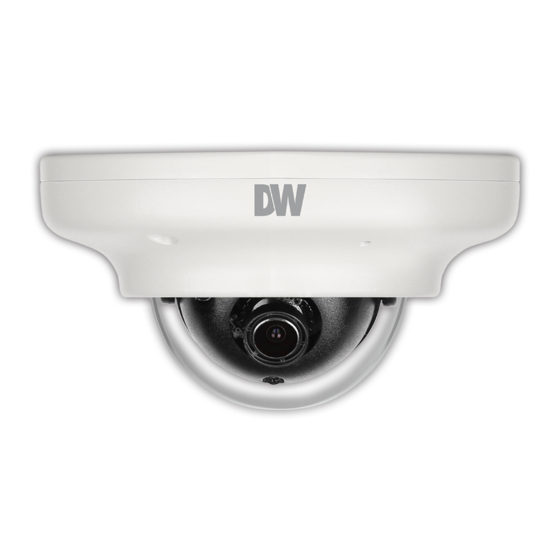
- Page 9 Part name Dome Cover Upper Case IR Switch Ambient Light Sensor Lens IR LED Tilt/Rotation Screw Cable Bottom Case Power Cable BNC Cable Test Video Output OSD Joystick Down...
- Page 10 Dimension Unit : 28.2 32.5...
-
Page 11: Product And Accessories
Product & Accessories Please check if all the camera and accessories are included in the package. Camera Cables Star Wrench Mount Bolt & Nut Test Video Cable (T-20) Template Sheet Screw & Manual for installing by Bolt & Nut Plastic Anchor-2pcs NOTE : The ‘Test Video Cable’... -
Page 12: Installation Instructions
Installation- Instructions Template Sheet Detach the camera’s cover dome from the camera’s module by unscrewing the three cover dome screws using the Torx Wrench. Use the camera or mounting template to mark and drill the necessary holes in the wall or ceiling. Pull wires through and make connections. - Page 13 Installation- Using Mount Bolt & Nut Detach the camera’s cover dome from the camera’s module by unscrewing the three cover dome screws. Template Sheet Using the camera or mounting template, mark and drill the necessary holes in the wall or ceiling. Secure the two long mounting screws to the camera’s base.
- Page 14 Connecting to Use the diagram below to connect to a Monitor or DVR properly. UNIVERSAL DVR 12VDC COAX Test Video Output Monitor - Power Connection - 12vdc Voltage - All cameras are equipped with a test video output for on-site configuration.
-
Page 15: Control Board
Control Board DOWN - OSD Joystick : The function setting and video output can be adjusted with OSD joystick. (default : HD-A) Image Mode Switches to HD-TVI mode when press OSD Joystick to left 5sec or longer. Switches to HD-A mode when press OSD Joystick to right 5sec or longer. Switches to CVBS mode when press OSD Joystick to up 5sec or longer. -
Page 16: Adjusting The Camera Angle
Adjusting the Camera angle Panning 360º Rotation 360º Tilting 70º NOTE: to adjust the camera's tilt, loosen the two screws connecting the camera's lens to the base of the camera. Once the camera module has been adjusted to the desired tilting angle, secure the screws back in place. -
Page 17: Osd Menu Tree
OSD Menu Tree NOTE : The function setting can be adjusted with both switch (OSD joystick) and remote control through UTC. In case of camera without OSD joystick, it can be adjusted with coaxial (UTC) only. LENS NR(Noise Reduction) 2DNR OFF / LOW / MIDDLE / HIGH P-IRIS MODE / LIMIT / RETURN... - Page 18 OSD Menu Lens MANUAL Manual mode supports the fixed board lens or the manual iris lens. P-IRIS If the camera includes a P-Iris lens, you can select this option to adjust the lens and iris settings. If P-Iris is selected, adjust the following : MODE : Select from AUTO or MANUAL.
- Page 19 OSD Menu Exposure SHUTTER EXPOSURE Set the camera’s shutter speed from available options (AUTO / 1/30~1/50000 / X2~X30 / FLK) SHUTTER 1/30 If Iris is set to AUTO in the lens menu, the camera’s shutter will be ----12 STARLIGHT AUTO set automatically and the values in this menu will not be adjustable.
- Page 20 OSD Menu Exposure(CONT.) DRC (Dynamic Range Compressor) DRC enables dark areas in images to become more visible without overexposing the bright areas to create one perfect image. Select from : OFF / ON / AUTO. If ON is selected, adjust the DRC value from 0~8. DEFOG Allows the camera to process a scene that is obscured by fog or weather conditions and provides a visibly improved image.
- Page 21 OSD Menu Backlight BLC (Back Light Compensation) If BLC is selected, adjust the size and position of the mask : - Level : Set the BLC levels LOW/MIDDLE/HIGH - AREA : Use the joystick controller on the camera’s board to adjust the zone’s position. Press the enter key and use the joystick controller to adjust the zone’s size.
- Page 22 OSD Menu White Balance MAIN MENU Auto Tracking White Balance Control mode compensates for color temperature changes between 2400K° and 11000K°. LENS MANUAL EXPOSURE BACKLIGHT PUSH WHITE BAL DAY&NIGHT AUTO Push fixes the white balace based on the current lighting auto- matically.
- Page 23 OSD Menu Day & Night - AUTO : Day/Night switch is based on the CDS levels (IR models) or AGC levels (non-IR models). - COLOR : The camera always stays in day/color mode. - B&W : The camera always stays in night/B&W mode. - EXT : The camera’s Day &...
- Page 24 OSD Menu Day & Night (CONT.) COLOR If COLOR mode is selected, the camera’s display will always appear in color, regardless of the lighting condition. - BURST : Select to enable or disable color burst when the camera switches from color to B/W. - IR SMART (0~15) : Enable Smart IR and set the level.
- Page 25 OSD Menu NR (Noise Reduction) NR reduces the noise on the screen in low light conditions and allows for clearer images, even at night. 2DNR : Set the Digital Noise Reduction values for general illumination. Select from LOW/MIDDLE/ HIGH. If the 2DNR settings are set to HIGH, image sharpness may be affected. 3DNR : Set the Digital Noise Reduction values for very low light situations.
- Page 26 OSD Menu Special CAM. TITLE Add a name to the camera. Set the title by using the OSD joystick. D-EFFECT FREEZE Freeze image from the camera at the selected moment. MIRROR Reflects the caemra : OFF / MIRROR / V-FLIP / ROTATE NEG.
- Page 27 OSD Menu Special (CONT.) MOTION - ALARM : VIEW TYPE : When motion is detected, select from the following disply options : 1. OFF - Do not display motion alarm 2. ALL - Show all motion zones when motion alarm is detected. 3.
- Page 28 OSD Menu Special (CONT.) PRIVACY - SELECT : The camera supports up to 4 separate privacy zones. Select which one to adjust. - DISPLAY : There are three types of privacy masks you can apply. Select from OFF MOSAIC, INV., or COLOR 1.
- Page 29 OSD Menu Special (CONT.) LANGUAGE Select from the available options : English, Chines 1, Chinese 2, German, French, Italian, Spanish, Polish, Russian, Portuguese, Dutch, Turkish, Korean, Japanese, Arabic, or Hebrew. DEFECT - LIVE DPC : 1. AGC LEVEL - Set the AGC levels for the Live DPC. 2.
- Page 30 OSD Menu Special (CONT.) DEFECT (CONT.) - BLACK DPC : 1. POS/SIZE : Set the size and position for the DPC Zone. BLACK DPC Use the joystick controller on the camera’s board to adjust POS/SIZE the zone’s position. Press the enter key and use the joystick START controller to adjust the zone’s size.
- Page 31 OSD Menu Adjust SHARPNESS Set the sharpness of the image. The Sharpness values can be increased or lowered according to the AGC levels in the camera’s view. If AUTO is selected, adjust the following values : - LEVEL : Set the sharpness level. The higher the number, the sharper the image will appear. - START AGC : Select the AGC value where the image’s shart lines may start to appear smeared in low light.
- Page 32 OSD Menu EXIT SAVE & END Save all changes made to the camera’s settings and exit the OSD menu. RESET The camera’s settings will be reset to their factory default values once you exit the OSD menu. NOT SAVE Exit the OSD menu without saving any changes made to the camera’s settings. MAIN MENU LENS MANUAL...
-
Page 33: Troubleshooting
Troubleshooting Before sending your camera for repair, check the following or contact our technical specialist. FOR NO VIDEO Check the coaxial cable and make sure it is connected securely. Check the power supply and make sure the camera has the proper voltage and current. FOR OUT-OF-FOCUS VIDEO Check the clear dome cover and the lens for dirt or fingerprints. -
Page 34: Specifications
Specifications VIDEO Image Sensor 1/2.7” CMOS Sensors Active Pixels 1920(H) x 1080(V) Scanning System Progressive scan Freguency 60Hz / 50Hz Signal Technology 2.0 Megapixel Universal Synchronization Internal Resolution 1920x1080 (1080p30fps) F2.0 (30IRE): 0.41 Lux (Color) Minimum Scene Illumination F1.4 (30IRE): 0 Lux (B&W) S/N Ratio 55dB Video Output... - Page 35 Specifications OPERATIONAL (CONT.) Digital Noise Reduction OFF / LOW / MIDDLE / HIGH White Balance ATW / PUSH / MANUAL / AWB Day and Night AUTO / COLOR / BW / EXT Auto Gain Control 0 ~ 15 Motion Detection ON/OFF (4 Zones) Privacy Zones ON/OFF (4 Zones)
- Page 36 This warranty gives you specific legal rights, and you may also have other rights that vary from state-to-state. If the problem is not handled to your satisfaction, then write to the following address: Digital Watchdog, Inc. ATTN: RMA Department 5436 W. Crenshaw Street...
- Page 37 Go to https://digital-watchdog.com/page/rma-landing-page/ to learn more about Digital Watchdog’s warranty and RMA. To obtain warranty or out of warranty service, please contact a technical support representative at: 1+ (866) 446-3595, Monday through Friday from 9:00 AM to 8:00 PM EST. A purchase receipt or other proof of the date of the original purchase is required before warranty service is rendered.
- Page 41 DW® East Coast Office and warehouse: 5436 W Crenshaw St, Tampa, FL 33634 DW® West Coast Office and warehouse: 16220 Bloomfield Ave., Cerritos, California, USA 90703 PH: 866-446-3595 | FAX: 813-888-9262 www.Digital-Watchdog.com technicalsupport@dwcc.tv Technical Support PH: USA & Canada 1+ (866) 446-3595 International 1+ (813) 888-9555 French Canadian 1+ (514) 360-1309 Technical Support hours:...
Need help?
Do you have a question about the STAR-LIGHT DWC-V7253 and is the answer not in the manual?
Questions and answers