Table of Contents
Advertisement
Quick Links
Advertisement
Table of Contents

Subscribe to Our Youtube Channel
Related Manuals for Digital Watchdog Star-Light DWC-V7253WTIR


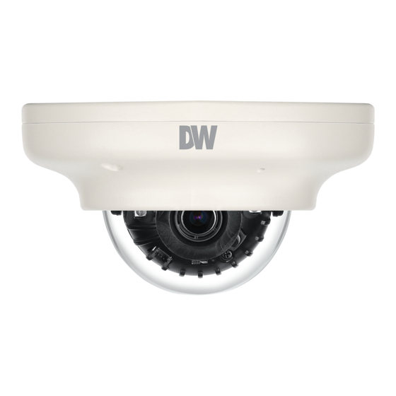
Summary of Contents for Digital Watchdog Star-Light DWC-V7253WTIR
- Page 1 User’s Manual 3/19...
- Page 2 INTRODUCTION INSTALLTION OSD MENU APPENDIX...
- Page 3 CAUTION CAUTION : WARNING WARNING...
- Page 4 PRECAUTION...
- Page 8 Part name Dome Cover Upper Case IR Switch Ambient Light Sensor Lens IR LED Tilt/Rotation Screw Test Video Output OSD Joystick Bottom Case Power Cable BNC Cable...
- Page 9 Dimension Unit : 28.2 32.5...
-
Page 10: Product And Accessories
Product & Accessories Please check if all the camera and accessories are included in the package. Camera Cables Screw & Mount Bolt & Nut Torx Wrench Plastic Anchor-2pcs Template Sheet Manual Test Video Cable for installing by Bolt & Nut NOTE : The ‘Test Video Cable’... -
Page 11: Installation Instructions
Installation- Instructions Template Sheet Detach the camera’s cover dome from the camera’s module by unscrewing the three cover dome screws using the Torx Wrench. Use the camera or mounting template to mark and drill the necessary holes in the wall or ceiling. Pull wires through and make connections. - Page 12 Installation- Using Mount Bolt & Nut Detach the camera’s cover dome from the camera’s module by unscrewing the three cover dome screws. Template Sheet Using the camera or mounting template, mark and drill the necessary holes in the wall or ceiling. Secure the two long mounting screws to the camera’s base.
- Page 13 Connecting to Use the diagram below to connect to an Universal DVR or CRT Monitor properly. UNIVERSAL DVR COAX 12VDC Test Video Output Monitor - Power Connection - 12vdc Voltage - All cameras are equipped with a test video output for on-site configuration. - OSD Joystick : The function setting and video output can be adjusted with OSD joystick.
-
Page 14: Control Board
Control Board DOWN Remove the camera’s dome cover to access ON/OFF the camera module and OSD joystick. Use the Joystick to control the camera’s OSD options. The camera has a manual IR switch, located under the camera’s lens. You can use this switch to manually turn the IR LED board on or off according to the installation needs. -
Page 15: Adjusting The Camera Angle
Adjusting the Camera angle Panning 360º Rotation 360º Tilting 70º NOTE: to adjust the camera's tilt, loosen the two screws connecting the camera's lens to the base of the camera. Once the camera module has been adjusted to the desired tilting angle, secure the screws back in place. -
Page 16: Osd Menu Tree
OSD Menu Tree NOTE : The function setting can be adjusted with both switch (OSD joystick) and remote control through RS485 or UTC. In case of camera without OSD joystick, it can be adjusted with coaxial (UTC) only. EXPOSURE MOTION LENS MANUAL / AUTO MOTION... - Page 17 OSD Menu Exposure LENS MANUAL : Manual mode supports the fixed board lens or the manual iris lens. AUTO : AUTO mode sets the camera’s iris automatically. EXPOSURE LENS LENS AUTO LEVEL BACKLIGHT BRIGHTNESS SHUTTER AUTO DEFOG FOCUS ADJ RETURN STARLIGHT 3D DNR HIGH...
- Page 18 OSD Menu Exposure BACKLIGHT HME HIGHLIGHT MASKING EXPOSURE HME allows objects to appear clearly on the screen by EXPOSURE masking extremely bright areas. To setup HME, set the level and color. The lower the setting, the darker the LENS AUTO BACKLIGHT masking areas have to be.
- Page 19 OSD Menu Exposure EXPOSURE DEFOG LENS AUTO MODE AUTO BACKLIGHT LEVEL ____ RETURN DEFOG STARLIGHT 3D DNR HIGH EXIT JUMP DRC ( DYNAMIC RANGE COMPRESSOR ) DRC enables dark areas in images to become more visible without overexposing the bright areas to create one perfect image.
-
Page 20: Color Gain
OSD Menu Color WB MODE COLOR WHITE BAL. WHITE BAL. AUTO C-TEMP 5000K COLOR GAIN R-GAIN B-GAIN EXIT JUMP RETURN AUTO Auto Tracking White Balance Control mode compensates for color temperature changes between 2500K ˚ and 12000K ˚. AUTO-EX Auto White Balance Control mode compensates for color temperature changes lower than 2500K ˚... - Page 21 OSD Menu Day & Night DAY/NIGHT MODE AUTO AGC THRES ____ AGC MARGIN ____ CDS THRES CDS MARGIN EXTERN SW EXT LED AUTO DELAY SMART IR EXIT JUMP MODE AUTO : Day/ Night switch will be based on the CDS levels. COLOR : The camera always stays in day/color mode.
- Page 22 OSD Menu Function FUNCTION SHARPNESS GAMMA 0.55 MIRROR FLIP EXIT JUMP SHARPNESS 0 ~ 10 - Sets the image sharpness. The higher the number, the sharper the image. GAMMA 0.45 ~ 0.75 - Select the desired gamma level. 0.55 is default setting. MIRROR / FLIP MIRROR : Reflects the camera horizontally.
- Page 23 OSD Menu Motion The camera can detect movement and display an alarm on the screen. when movement is detected. MOTION DET WINDOW MOTION WINDOW USE DET WINDOW WINDOW ZONE DET TONE DET H-POS DET V-POS MDRECT FILL DET H-SIZE SENSITIVITY DET V-SIZE MOTION OSD RETURN...
- Page 24 OSD Menu Privacy You can hide some parts of the screen for privacy masking. A total of 16 different privacy masking zones are available. The cameras support square privacy masks or advanced polygon masks. PRIVACY PRIVACY ZONE NUM ZONE DISP H-POS V-POS H-SIZE...
- Page 25 OSD Menu Setup COMMUNICA SETUP CAM ID BAUDRATE 9600 COMMUNICA SET DONE CAM TITLE RETURN IMAGE RANGE FULL FREQ 60Hz LANGUAGE INITIAL EXIT JUMP COMMUNICATION Adjust the camera’s ID and Baudrate. Default Protocol is Pelco-D. - CAM ID : Provide an ID number for the camera (0 ~ 255). - BAUDRATE : 9600bps is default.
- Page 26 OSD Menu Setup SETUP COMMUNICA CAM TITLE IMAGE RANGE FULL FREQ 60Hz LANGUAGE INITIAL EXIT JUMP FREQ When the camera’s image appears to have flickering issues, change the frequency value to adjust the image. LANGUAGE Select from the following: English (Default), Chinese, Chinese (S), Japanese, and Koran. INITIAL Reset the camera to its default settings.
-
Page 27: Save And Exit
OSD Menu EXIT EXIT SAVE&EXIT EXIT SAVE & EXIT Exit the OSD menu after saving the recent changes. EXIT Exit the OSD menu without saving any changes. -
Page 28: Troubleshooting
Troubleshooting Before sending your camera for repair, check the following or contact our technical specialist. FOR NO VIDEO Check the coaxial cable and make sure it is connected securely. Check the power supply and make sure the camera has the proper voltage and current. FOR OUT-OF-FOCUS VIDEO Check the clear dome cover and the lens for dirt or fingerprints. -
Page 29: Specifications
Specifications VIDEO Image Sensor 1/3” CMOS Sensors Active Pixels 1944(H) x 1092(V) Scanning System Progressive scan Freguency 60Hz / 50Hz Signal Technology 2.0 Megapixel Universal Synchronization Internal Resolution 1920x1080 (1080p30fps) F2.0 (30IRE): 0.06 Lux (Color) Minimum Scene Illumination F2.0 (30IRE): 0 Lux (B&W) S/N Ratio 55dB Video Output... - Page 30 Specifications OPERATIONAL (CONT.) Digital Noise Reduction OFF / LOW / MIDDLE / HIGH White Balance AUTO / AUTO-EX / PRESET / MANUAL Day and Night AUTO/COLOR/B&W/EXTERN Auto Gain Control 0 ~ 10 Motion Detection ON/OFF (4 Zones) Privacy Zones ON/OFF (16 Zones) Sharpness 0 ~ 10 Gamma...
- Page 31 This warranty gives you specific legal rights, and you may also have other rights that vary from state-to-state. If the problem is not handled to your satisfaction, then write to the following address: Digital Watchdog, Inc. ATTN: RMA Department 5436 W. Crenshaw Street...
- Page 32 Digital Watchdog (referred to as “the Warranter”) warrants the Digital Watchdog Camera against defects in materials or workmanship as follows: LABOR: For the initial five (5) years and one (1) year on IR LED from the original purchase date, if the camera is determined to be defective, the Warranter will repair or replace the unit with a new or refurbished product at its option at no charge.
Need help?
Do you have a question about the Star-Light DWC-V7253WTIR and is the answer not in the manual?
Questions and answers