Planet WSD-800 User Manual
8-port 10/100mbps + 1-2 gigabit tp/sfp combo managed ethernet switch
Hide thumbs
Also See for WSD-800:
- User manual (66 pages) ,
- User manual (66 pages) ,
- Quick installation manual (8 pages)

Related Manuals for Planet WSD-800


Summary of Contents for Planet WSD-800
- Page 1 User’s Manual of WSD-800 / WGSD-910/WGSD-1022C User's Manual WSD-800 8-Port 10/100Mbps WGSD-910 8-Port 10/100Mbps + 1 Gigabit TP/SFP Combo WGSD-1022C 8-Port 10/100Mbps + 2 Gigabit TP/SFP Combo Managed Ethernet Switch...
- Page 2 Trademarks Copyright © PLANET Technology Corp. 2008. Contents subject to which revision without prior notice. PLANET is a registered trademark of PLANET Technology Corp. All other trademarks belong to their respective owners. Disclaimer PLANET Technology does not warrant that the hardware will work properly in all environments and applications, and makes no warranty and representation, either implied or expressed, with respect to the quality, performance, merchantability, or fitness for a particular purpose.
-
Page 3: Table Of Contents
YSTEM 4.4.1 IP Configuration...27 4.4.2 SNMP ...28 4.4.2.1 Theory ...28 4.4.3 Password...32 4.4.4 CONSOLE ...32 4.4.5 System Upgrade...32 4.4.6 Saving Parameters...33 4.4.7 Parameters Backup & Recovery ...33 User’s Manual of WSD-800 / WGSD-910/WGSD-1022C Table of Contents ...17 ...17 ...26 ...26... - Page 4 5. TROUBLE SHOOTING...94 5.1 I ...94 NCORRECT CONNECTIONS 5.1.1 Faulty or loose cables ...94 5.1.2 Non-standard cables ...94 5.1.3 Improper Network Topologies...94 5.2 D LED I IAGNOSING NDICATORS 5.2.1 Cabling ...95 6. APPENDIX ...96 User’s Manual of WSD-800 / WGSD-910/WGSD-1022C ...94...
- Page 5 6.2 100BASE-TX/10BASE-T P 7. APPENDIX-B ...98 802.1Q VLAN M ULTI 802.1Q VLAN - M ULTI 802.1Q VLAN - M ULTI User’s Manual of WSD-800 / WGSD-910/WGSD-1022C ...96 ...97 SSIGNMENTS VLAN 1 ...98 NTAGGED SETTING SAMPLE VLAN NTAGGED SETTING SAMPLE...
-
Page 6: Introduction
Chapter 6, APPENDIX The chapter contains cable information of the Switch. In the following section, terms "Switch" means the three Switch devices, ie. WSD-800, WGSD-910 and WGSD-1022C; Terms with lower case "switch" means any Ethernet switches. User’s Manual of WSD-800 / WGSD-910/WGSD-1022C... -
Page 7: Product Feature
8-Port 10/100Mbps TP interfaces with 1 port Gigabit combo (WGSD-910) ▫ 8-Port 10/100Mbps TP interfaces with 2 port Gigabit combo (WGSD-1022C) ▫ High back-plane bandwidth 1.6Gbps / 3.6Gbps / 5.6Gbps (WSD-800 / WGSD-910 / WGSD-1022C) ▫ Console/Web/SNMP management ▫ Configuration backup and recovery ▫... - Page 8 Traffic classification based on Port Number, 802.1p priority, DS/TOS field in IP Packet v1 and v2 IGMP Snooping Allow to disable or enable. Per port bandwidth control Ingress: 500Kb~80Mbps Bandwidth Control Egress: 64Kb~80Mbps RX/TX/Both Port Mirror User’s Manual of WSD-800 / WGSD-910/WGSD-1022C 2.67Mpps 4.16Mpps...
- Page 9 IEEE 802.3x Flow Control and Back pressure Standards Compliance IEEE 802.1d Spanning tree protocol IEEE 802.1w Rapid spanning tree protocol IEEE 802.1p Class of service IEEE 802.1Q VLAN Tagging IEEE 802.1x Port Authentication Network Control User’s Manual of WSD-800 / WGSD-910/WGSD-1022C...
-
Page 10: Installation
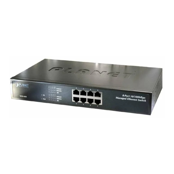
2.1 Product Description 2.1.1 Product Overview With 8-Port 10/100Mbps, the PLANET WSD-800 / WGSD-910 / WGSD-1022C boast a high performance switch architecture that is capable of providing non-blocking switch fabric and wire-speed throughput as high as 1.6Gbps / 3.6Gbps / 5.6Gbps. -
Page 11: Led Indications
■ Per 10/100Base-TX RJ-45 Port ( Port-1 to Port-8) Color LNK/ACT Blink to indicate that the Switch is actively sending or receiving data over that Orange port. FDX/COL Lights to indicate respective port is in full duplex (FDX) mode. Otherwise, it is Green OFF for half duplex (HDX) operations. -
Page 12: Switch Rear Panel
Orange Off: indicate that the port is operating at 2.1.4 Switch Rear Panel Figure 2-4 shows the rear panel of WSD-800. Figure 2-5 shows the rear panel of WGSD-910 / WGSD-1022C. Figure 2-5 WGSD-910 / WGSD-1022C rear panel. The device is a power-required device, it means, it will not work till it is powered. If... -
Page 13: Install The Switch
Step4: Connect the Switch to network devices. A. Connect one end of a standard network cable to the 10/100/1000 RJ-45 ports on the front of the Switch B. Connect the other end of the cable to the network devices such as printer servers, workstations or routers…etc. -
Page 14: Rack Mounting
Step3: Secure the brackets tightly. Step4: Follow the same steps to attach the second bracket to the opposite side. Step5: After the brackets are attached to the Switch, use suitable screws to securely attach the brackets to the rack, as shown in Figure 2-8. -
Page 15: Installing The Sfp Transceiver
PLANET SFP transceivers is correct at the time of publication: ■MGB-SX SFP (1000Base-SX SFP transceiver ) ■MGB-LX SFP (1000Base-LX SFP transceiver ) It recommends using PLANET SFPs on the Switch. If you insert a SFP transceiver that is not Notice: supported, the Switch will not recognize it. - Page 16 Connect the other end of the cable to a device – switches with SFP installed, fiber NIC on a workstation or a Media Converter. Check the LNK/ACT LED of the SFP slot on the front of the Switch. Ensure that the SFP transceiver is operating correctly.
-
Page 17: Console Management
The console port is a female DB-9 connector that enables a connection to a PC or terminal for monitoring and configuring the Switch. Use the supplied RS-232 cable with a male DB-9 connector to connect a terminal or PC to the Console port. -
Page 18: Console Management
User’s Manual of WSD-800 / WGSD-910/WGSD-1022C After finished the parameter settings, click “OK“. When the prompt shows “Switch>”, type “?” for help or type “enable” for further configuration. The system needs password for further configuration. After the “enable” command, the system asks for password, please enter “admin” for the default password. As shows in the... -
Page 19: Telnet Login
3.4 Telnet login The Switch also supports telnet for remote management. The Switch asks for user name and password for remote login when using telnet, please use “admin” for username and “admin” for password. 3.5 Commands There are two levels for console commands. The first level provides commands to show system informations and current configurations. -
Page 20: Privileged Command
To access to the second level, enter the “enable” command in the first level. The sysem then prompt for a password. Please enter “admin” for the password. The promt then changes to “Switch\enable>”. Entering a question mark "?" at the prompt displays the list of commands available for command mode. -
Page 21: Copy Command
Disable command is to exit the privileged mode and back to the first level of command line interface. Command Disable User’s Manual of WSD-800 / WGSD-910/WGSD-1022C Restore spanning tree port priority to default value Clear strom limit of all ports... -
Page 22: Reboot Command
Reboot command is to reboot the Switch, please beware to check if the configuration is saved.. Command Reboot 3.5.2.5 Set command Set command is to change the parameter of the Switch functions. The follow table lists the set commands and the equivalent usages. Command set channel... - Page 23 MAC-aging set security filter-MAC User’s Manual of WSD-800 / WGSD-910/WGSD-1022C Set ipstack disable Set ipstack group STR Set ipstack mac-addr Set ipstack mode master/client Set ipstack system-priority...
-
Page 24: Show Command
3.5.2.6 Show command Show command is to display the current parameter of the Switch functions. The follow table lists the show commands and the equivalent usages. Command show channel... - Page 25 User’s Manual of WSD-800 / WGSD-910/WGSD-1022C Show igmp snooping information Show http server information Show telnet server information Show ipstack info Show mirror information Show multicast router port information...
-
Page 26: Web-Based Management
The main web page of the Web-based management appears. As shows in the following screen. Notice: The following section will base on the console screens of WSD-800, for WGSD-910 / WGSD-1022C the display will be the same to WSD-800. User’s Manual of WSD-800 / WGSD-910/WGSD-1022C 4. -
Page 27: System
The Switch can be managed by the Web/Telnet/SNMP interfaces. Administrators can access the management interface via the IP address of the Switch. The default IP address of the Switch is 192.168.0.100. You can change the IP address to be in the same IP segment as your LAN network for convinence. -
Page 28: Snmp
2. The changed IP address take effect immediately after click on the OK button, you need to use the new IP address to access the Web interface. 3. The changed IP address remains the original after reboot the Switch unless the configuration is saved. To save the changed IP address, please move to System/Saving Parameters menu. -
Page 29: Snmp Configuration
The followings are the description of the sub-table. 1. SNMP Agent Status Configuration This block enables to turn on SNMP Agent. Enabled / Disabled: To turn on or turn off the SNMP function on the Switch. User’s Manual of WSD-800 / WGSD-910/WGSD-1022C -29-... - Page 30 Use this table to configure the SNMP community strings and define the policy of the relative string. The community string acts like a password to permit access to the agent on the Switch. One or more of the following characteristics can be associated with the community string: Add Community: enter private or public 。...
- Page 31 A trap manager is a management station (SNMP application) that receives traps (the system alerts generated by the Switch). If no trap manager is defined, no traps are issued. Create a trap manager by entering the IP address of the station and a community string.
-
Page 32: Password
User’s Manual of WSD-800 / WGSD-910/WGSD-1022C 4.4.3 Password The Password management menu is to set or change the password of the Web Management Interface. Click on System/Password menu button, and the Modify Password table shows in the main web page. -
Page 33: Saving Parameters
It takes effect immediately when you change the parameters of the management function when the Switch is running. But the parameters would not be saved after reboot the Switch. To keep the changed parameters, Click on the System/Saving Parameters menu button, and click on the “Save” button on the web main page as show in the following. -
Page 34: Load Default
User’s Manual of WSD-800 / WGSD-910/WGSD-1022C 4.4.8 Load Default This function is to reset the configuration of Switch to the factory default. Click on the System/Load Default menu button, and the following table shows in the web main page. CAUTION: This operation will result in all the parameters losing. -
Page 35: Port Management
Atual: Displays the negotiation result. 。 4.5.2 Port Statistics The Port Statistics page provides a view of the current status of every port on the Switch. Pressing the “Reset” button will reset all port counters to zero. User’s Manual of WSD-800 / WGSD-910/WGSD-1022C... -
Page 36: Port Band Restrict
(at the time of a primary link failure) is also accomplished automatically without operator intervention. This automatic network reconfiguration provides maximum uptime to network users. However, the concepts of the User’s Manual of WSD-800 / WGSD-910/WGSD-1022C -36-... - Page 37 Creating a Stable STP Topology It is to make the root port a fastest link. If all switches have STP enabled with default settings, the Switch with the lowest MAC address in the network will become the root Switch. By increasing the priority (lowering the priority number) of the best switch, STP can be forced to select the best switch as the root Switch.
- Page 38 In addition, STP specifies a series of states a port must transition through to further ensure that a stable network topology is created after a topology change. Each port on a switch using STP exists is in one of the following five states: Blocking – the port is blocked from forwarding or receiving packets 。...
- Page 39 STP Operation Levels The Switch allows for two levels of operation: the Switch level and the port level. The level forms a spanning tree consisting of links between one or more switches. The port level constructs a spanning tree consisting of groups of one or more ports.
- Page 40 BPDU packets sent by the Root Bridge to tell all other Switches that it is indeed the Root Bridge. If you set a Hello Time for your Switch, and it is not the Root Bridge, the set Hello Time will be used if and when your Switch becomes the Root Bridge.
- Page 41 STP assistance is not applied. If switch A broadcasts a packet to switch B, switch B will broadcast it to switch C, and switch C will broadcast it to back to switch A ... and so on. The broadcast packet will be passed indefinitely in a loop, potentially causing a network failure.
-
Page 42: Spanning Tree Configuration
LAN 2 The switch with the lowest Bridge ID (switch C) was elected the root bridge, and the ports were selected to give a high port cost between switches B and C. The two (optional) Gigabit ports (default port cost = 4) on switch A are connected to one (optional) Gigabit port on both switch B and C. - Page 43 True - This port connected directly to a end-node device or LAN segment where a loop cannot be 。 created False – This port connected to one or more LAN segments – maybe a ethernet switch or HUB, that a 。 loop might be occured P2P Status: Enables or disables the device to establish a point-to-point link, or specifies for the device to automatically establish a point-to-point link.
- Page 44 128.The lower number has the highest priority. Path Cost: Specifies the path cost of the port. The switch uses this parameter to help determine which port will become a forwarding port. Lower numbers will be used as forwarding ports first. The range is from 0 to 65535. The default values based on IEEE802.1D are: 10Mb/s = 50-600, 100Mb/s = 10-60, 1000Mb/s = 3-10...
-
Page 45: Link Aggregation
If the group is defined as a local static link aggregationing group, then the number of ports must be the same as the group member ports. User’s Manual of WSD-800 / WGSD-910/WGSD-1022C -45-... -
Page 46: Security
A weighted round robin system is employed on the Switch to determine the rate at which the queues are emptied of packets. The ratio used for clearing the queues is 4:1. This means that the highest priority queue, Queue 1, will clear 4 packets for every 1 packet cleared from Queue 0. - Page 47 Port-based VLAN Port-based VLAN limit traffic that flows into and out of switch ports. Thus, all devices connected to a port are members of the VLAN(s) the port belongs to, whether there is a single computer directly connected to a switch, or an entire department.
- Page 48 User’s Manual of WSD-800 / WGSD-910/WGSD-1022C headers. The tagging feature allows VLAN to span multiple 802.1Q-compliant switches through a single physical connection and allows Spanning Tree to be enabled on all ports and work normally. Any port can be configured as either tagging or untagging. The untagging feature of IEEE 802.1Q VLAN allow VLAN to work with legacy switches that don’t recognize VLAN tags in packet headers.
- Page 49 VID for tagged packets, tag-aware and tag-unaware network devices can coexist on the same network. A switch port can have only one PVID, but can have as many VID as the switch has memory in its VLAN table to store them.
-
Page 50: Vlan Configuration
Default VLANs The Switch initially configures one VLAN, VID = 1, called "default." The factory default setting assigns all ports on the Switch to the "default". As new VLAN are configured in Port-based mode, their respective member ports are removed from the "default."... - Page 51 802.1Q VLAN Configuration There are up to 256 configurable VLAN groups. By default when 802.1Q is enabled, all ports on the switch belong to default VLAN (VID 1). The default VLAN cannot be deleted. Understand nomenclature of the Switch Tagging and Untagging Every port on an 802.1Q compliant switch can be configured as tagging or untagging.
- Page 52 Set the port VLAN ID that will be assigned to untagged traffic on a given port. This feature is useful for accommodating devices that you want to participate in the VLAN but that don’t support tagging. The Switch allows each port to set one PVID, the range is 1~255, default PVID is 1. The PVID must be the same as the VLAN ID that the port was defined as belonging to in the VLAN group, or the untagged traffic will be dropped.
- Page 53 Set the port VLAN ID that will be assigned to untagged traffic on a given port. This feature is useful for accommodating devices that you want to participate in the VLAN but that don’t support tagging. User’s Manual of WSD-800 / WGSD-910/WGSD-1022C -53-...
- Page 54 User’s Manual of WSD-800 / WGSD-910/WGSD-1022C 5. Trunk configuration: If the Trunk type is chosen, please follow the steps to set the Trunk of the port. 5.1 Add and define the names and VIDs for new VLANs. The VID number ranges from 2 to 4094. Fill the VID field and the VLAN Name field in the Set VLAN’s VID &...
-
Page 55: Mac Address Bind
4.7.2 MAC Address Bind This function is based upon for the Switch security. When you add one MAC Address is bind with one port. It remains in the Switch's address table, regardless of whether the device is physically connected to the Switch. This saves the Switch from having to re-learn a device's MAC address after it has been disconnected or powered-off from the network, and then reconnected at some time later. -
Page 56: Mac Address Filtering
User’s Manual of WSD-800 / WGSD-910/WGSD-1022C 4.7.3 MAC Address Filtering MAC address filtering allows the Switch to drop unwanted traffic. Traffic is filtered based on the destination addresses. To filter the MAC Address, click on the Security/MAC Address Filtering menu button, the main web page then shows the MAC Address Filtering function table. -
Page 57: Mac Address Learning
4.7.5 MAC Address Aging Time The Aging Time affects the learning process of the Switch. Dynamic forwarding table entries, which are made up of the source and destination MAC addresses and their associated port numbers, are deleted from the table if they are not accessed within the aging time. -
Page 58: Port-Based Network Access Control
Switch will broadcast the packet to all ports, negating many of the benefits of having a Switch. Static forwarding entries are not affected by the aging time. - Page 59 Authentication server—performs the actual authentication of the client. The authentication server validates the identity of the client and notifies the Switch whether or not the client is authorized to access the LAN and switch services. Because the Switch acts as the proxy, the authentication service is transparent to the client.
- Page 60 Authentication Initiation and Message Exchange The Switch or the client can initiate authentication. If you enable authentication on a port by using the dot1x port-control auto interface configuration command, the Switch must initiate authentication when it determines that the port link state transitions from down to up. It then sends an EAP-request/identity frame to the client to request its identity (typically, the Switch sends an initial identity/request frame followed by one or more requests for authentication information).
- Page 61 Ports in Authorized and Unauthorized States The Switch port state determines whether or not the client is granted access to the network. The port starts in the unauthorized state. While in this state, the port disallows all ingress and egress traffic except for 802.1X protocol packets.
- Page 62 4.7.6.2 802.1X Configuration This Switch has two 802.1X Mode: Radius Server & Local Authenticate choose one you need ● Local Authenticate — In this situation, do not need Radius server in the network, all authentication completed by 802.1x Switch,the normal topologies as below 1.
- Page 63 Force unauthorized: causes the port to remain in the unauthorized state, ignoring all attempts by the client 。 to authenticate. The switch cannot provide authentication services to the client through the interface. Maximum account number: the biggest user's quantity of passing authentication under this port, set 1,...
- Page 64 ● Radius Server — In this situation, need a Radius server in the network, the normal topologies as below Select the “Radius Server” mode. The RADIUS Server configuration table includes the following fields: User’s Manual of WSD-800 / WGSD-910/WGSD-1022C -64-...
- Page 65 IP Address of the Web-Smart switch with 192.168.0.100. And also make sure the shared secret key is as same as the one you had set at the switch RADIUS server – 12345678 at this case. User’s Manual of WSD-800 / WGSD-910/WGSD-1022C...
- Page 66 Set the Ports Authenticate Status to “Force Authorized” if the port is connected to the RADIUS NOTE: server or the port is a uplink port that is connected to another switch. Or once the 802.1X stat to work, the switch might not be able to access the RADIUS server.
- Page 67 User’s Manual of WSD-800 / WGSD-910/WGSD-1022C Enter ” Active Directory Users and Computers”, create legal user data, the next, right-click a user what you created to enter properties, and what to be noticed: -67-...
-
Page 68: X Client Configuration
The following procedures show how to configure 802.1X Authentication in Windows XP. Please note that if you want to change the 802.1x authentication type of a wireless client, i.e. switch to EAP-TLS from EAP-MD5, you must remove the current existing wireless network from your preferred connection first, and add it in again. - Page 69 Select “MD-5 Challenge” from the drop-down list box for EAP type. Click “OK”. When wireless client has associated with WSD-800 / WGSD-910, a user authentication notice appears in system tray. Click on the notice to continue. User’s Manual of WSD-800 / WGSD-910/WGSD-1022C...
- Page 70 User’s Manual of WSD-800 / WGSD-910/WGSD-1022C Enter the user name, password and the logon domain that your account belongs. 10. Click “OK” to complete the validation process. -70-...
-
Page 71: Qos
Classifier-classifies the traffic on the network. Traffic classifications are determined by protocol, application, source, destination, and so on. You can create and modify classifications. The Switch then groups classified traffic in order to schedule them with the appropriate service level. -
Page 72: Qos Configuration
Apply a classifier to determine how the incoming traffic will be classified and thus treated by the Switch. Create a QoS profile which associates a service level and a classifier. Apply a QoS profile to a port(s). 4.8.2 QOS Configuration QoS settings allow customization of packet priority in order to facilitate delivery of data traffic that might be affected by latency problems. - Page 73 Fill the mapping number in the CoS (0-7) field. Click on the “OK” button to save. To remove the VLAN-CoS mapping item, simply click on the “Delete” button in the Show VLAN-CoS Mapping table. User’s Manual of WSD-800 / WGSD-910/WGSD-1022C -73-...
- Page 74 802.1p compliant devices, a tag inserted into the packet header is used to identify the priority level of data packets. Fill the 802.1p Priority (0-7) field in the 802.1p-priority-CoS Mapping Configuration Table. Fill the mapping number in the CoS (0-7) field. Click on the “OK” button to save. User’s Manual of WSD-800 / WGSD-910/WGSD-1022C -74-...
- Page 75 Click on the “OK” button to save. 5. COS-Queue Mapping Fill the CoS (0-7) field in the CoS-Queue Mapping Configuration Table. Fill the mapping number in the Queue (0-3) field. Click on the “OK” button to save. User’s Manual of WSD-800 / WGSD-910/WGSD-1022C -75-...
- Page 76 User’s Manual of WSD-800 / WGSD-910/WGSD-1022C 6. Queue Management There are two rules for the Priority Queue: Weighted Round Robin (WRR) and Always Hight. To configure Queue Rule, select the Queue Policy drop down menu in the Queue Rule Configuration table. And Click on the “OK”...
-
Page 77: Multicast
IGMP packets enable multicast routers to keep track of the membership of multicast groups, on their respective sub networks. The following outlines what is communicated between a multicast router and a multicast group member using IGMP. A host sends an IGMP “report” to join a group User’s Manual of WSD-800 / WGSD-910/WGSD-1022C Checksum -77-... -
Page 78: Igmp Snooping Configuration
Immediate-Leave: Indicates the port , which will be limited for the accepted IGMP groups Forwarding all leave pkt: Use to limit the number of IGMP groups that an interface can accept. The possible value as following: User’s Manual of WSD-800 / WGSD-910/WGSD-1022C Non-Member Leave Group... -
Page 79: Igmp Port Policy
4.9.3 IGMP Port Policy For the security and management issue, the Switch is allowed to limiti the number of multicast groups by a specific port. With system default setting, all the learned Multicast groups are accepted and forwarded. Atter the IGMP Port Policy be configured on a specific port, the Switch will restrict the number of IGMP groups according to the parameter. - Page 80 Fill the accepted number in the Group Number field. ( For this case, 4 multicast groups are allowed) Click on the “OK” button to save. The worksatation that connect to Port-2 start to send IGMP Join/Report packets. Select “IGMP Snooping Configuration” page to show the Multicast Group Table. User’s Manual of WSD-800 / WGSD-910/WGSD-1022C -80-...
-
Page 81: Igmp Group Policy
Set IGMP Group Policy Index: Assign a No. 1~24 for the Multicast Group as a index for easy managment Multicast Group: Identifies the Multicast group IP address (The valued range is from 224.0.0.1 ~239.255.255.254) User’s Manual of WSD-800 / WGSD-910/WGSD-1022C -81-... - Page 82 Select the specific port that will be assigned to force accept static Multicast Group stream. Field in the Index number that assigned with “239.1.1.1. ( For this case, Select Port-1 with index 1) Click on the “Add” button to take effect. User’s Manual of WSD-800 / WGSD-910/WGSD-1022C -82-...
- Page 83 User’s Manual of WSD-800 / WGSD-910/WGSD-1022C -83-...
-
Page 84: Static Routing Port
VLANs to be the multicast group members. After that, ports belong to the member VLANs are able to receive multicast traffic cross VLAN. But they are not able to access each other. User’s Manual of WSD-800 / WGSD-910/WGSD-1022C -84-... - Page 85 VLAN 2 and VLAN 3 as the Multicast group memebers. Assign the Static Routing Port, here we assign Port-2 as the Static Routing Port of VLAN 6. As following screen appears. User’s Manual of WSD-800 / WGSD-910/WGSD-1022C -85-...
-
Page 86: Vlan Configure
At Step-3, we had set Port-2 as VLAN 6 Static Routing Port, so we have to configure Port-2 as VLAN 6 member port. Cooperate with IGMP Snooping,and 802.1Q VLAN,Port-6 of VLAN 2 and Port-7 of VLAN 3 are able to receive the Multicast group traffic from Port-2 with different VLAN groups setting User’s Manual of WSD-800 / WGSD-910/WGSD-1022C -86-... -
Page 87: Port Analysis
Port Mirroring is a method of monitoring network traffic that forwards a copy of each incoming and/or outgoing packet from one port of a network switch to another port where the packet can be studied. It enables the manager to keep close track of switch performance and alter it if necessary. -
Page 88: Storm Control
Flow field. Click on the “OK” button to save. To remove the Storm Restricting function on the port, simpy click on the “Delete” button in the Show Port Restricting Table table. User’s Manual of WSD-800 / WGSD-910/WGSD-1022C -88-... -
Page 89: Ip Stacking
IP Stacking function enables you to use a single IP address and standard network cabling to manage a group of up to 8 PLANET WSD-800 / WGSD-910 / WGSD-1022C / WSW-2401A / WGSW-2840 / WGSW-5240 Switches in the same IP subnet (broadcast domain). - Page 90 Please enter into switch web main screen and choose “Enable” in Management status field. It will enable the stack function of the switch and the following screen appears. Then assign a role to the WSD-800 / WGSD-910 / WGSD-1022C / WSW-2401A / WGSW-2840 / User’s Manual of WSD-800 / WGSD-910/WGSD-1022C...
- Page 91 WGSW-5240 Switches as Master in Management mode field, the following screen appears. Enter a string in the “IP Stacking Group” field; the default string of the WSD-800 / WGSD-910 / WGSD-1022C / WSW-2401A / WGSW-2840 / WGSW-5240 Switches is “planet_switch”. This string must be the same with the Client switches that to be assigned to the same IP Stack group.
- Page 92 Enter a string in the “IP Stacking Group” field; the default string of the WSD-800 / WGSD-910 / WGSD-1022C / WSW-2401A / WGSW-2840 / WGSW-5240 Switches is “planet_switch”. This string must be the same with the Master switch that to be assigned to the same IP Stack group.
- Page 93 User’s Manual of WSD-800 / WGSD-910/WGSD-1022C Please do not assign role for whole stack member Switch as client, it cannot detect the Master NOTE: device with minimum MAC address. -93-...
-
Page 94: Trouble Shooting
User’s Manual of WSD-800 / WGSD-910/WGSD-1022C 5. TROUBLE SHOOTING This section is intended to help you solve the most common problems on the WSD-800 / WGSD-910 Managed Ethernet Switch 5.1 Incorrect connections The switch port can auto detect straight or crossover cable when you link switch with other Ethernet device. For the RJ-45 connector should use correct UTP or STP cable, 10/100Mbps port use 2 pairs twisted cable. -
Page 95: Cabling
User’s Manual of WSD-800 / WGSD-910/WGSD-1022C 5.2.1 Cabling RJ-45 ports: use unshielded twisted-pair (UTP) or shield twisted-pair (STP) cable for RJ-45 connections: 100Ω Category 3, 4 or 5 cable for 10Mbps connections or 100Ω Category 5 cable for 100Mbps connections. Also be sure that the length of any twisted-pair connection does not exceed 100 meters (328 feet). -
Page 96: Appendix
6.1 Console Port Pin Assignments The DB-9 serial port on the front panel is used to connect to the switch for out-of-band console configuration. The console menu-driven configuration program can be accessed from a terminal or a PC running a terminal emulation program. - Page 97 "+" and "-" signs represent the polarity of the wires that make up each wire pair. Note: All ports on this switch support automatic MDI/MDI-X operation, you can use straight-through cables for all network connections to PCs or servers, or to other switches or hubs. In straight-through cable, pins 1, 2, 3, and 6, at one end of the cable, are connected straight through to pins 1, 2, 3 and 6 at the other end of the cable.
- Page 98 At the menu bar ,click “Security” > “ VLAN” After the VLAN configuration page appear, select “802.1Q VALN“ and clink “OK” to apply. Then the following screen in Figure 7-2 appears. User’s Manual of WSD-800 / WGSD-910/WGSD-1022C Figure 7-1 Overlap VLAN graphic -98-...
- Page 99 At the Port 1-VLAN Port configuration page, select VLAN 2 and VLAN 3 to add to the Port 1. The right information window at this table shows the status. The screen in Figure 7-4 appears. User’s Manual of WSD-800 / WGSD-910/WGSD-1022C Figure 7-2 802.1Q VLAN page screen...
- Page 100 • And both Port 2 and Port 3 are VLAN 1 members. 10. After properly configure the 802.1Q VLAN per port setting, it should be as the screen in Figure 7-6 appears. User’s Manual of WSD-800 / WGSD-910/WGSD-1022C Figure 7-5 Port 1 VLA N status...
- Page 101 User’s Manual of WSD-800 / WGSD-910/WGSD-1022C Figure 7-6 Port 1, Port 2 and Port 3 VLAN configuration Although Port 2 and Port 3 are VLAN 1 members, with different PVID setting, the two ports are not able to access each other. But they all can access with the server/AP/Printer which connect to the Port 1 now.
- Page 102 Port28 Trunk WGSW-2840_192.168.0.20 Edge-Switch VLAN Configuration 192.168.0.20 VLAN Configuration Port Link Type Port1 Always Untag Port2 Always Untag User’s Manual of WSD-800 / WGSD-910/WGSD-1022C Major Member WGSW-2840_220 WGSW-2840_10 WGSW-2840_20 WGSW-2840_30 Server Network_Printer_1 Network_Printer_2 Clinets connect to [192.168.0.10] Clinets connect to [192.168.0.20] Clinets connect to [192.168.0.30]...
- Page 103 WGSW-2840_192.168.0.30 Edge-Switch VLAN Configuration 192.168.0.30 VLAN Configuration Port Link Type Port1 Always Untag Port2 Always Untag Port3 Always Untag Port28 Trunk User’s Manual of WSD-800 / WGSD-910/WGSD-1022C Untag=1,2,3,4 NtworkPrinter Tag=1,2,3,4 Core-2840 PVID Egress Link Partner Untag=1,4 Untag=1,4 Untag=1,4 Tag=1,2,3,4 Core-2840...
- Page 104 802.1Q VLAN - Multi-Untagged VLAN setting sample 3 VLAN Group Membership VLAN ID VLAN Define VLAN 1 Public VLAN VLAN 2 VLAN 3 User’s Manual of WSD-800 / WGSD-910/WGSD-1022C Major Member WGSW-2840_220 WGSW-2840_10 WGSW-2840_20 WGSW-2840_30 Server Network_Printer_1 Network_Printer_2 Client connect to Ports those be assigned to VLAN 2 ,at [192.168.0.10] switch...
- Page 105 Always Untag Port3 Always Untag Port28 Trunk User’s Manual of WSD-800 / WGSD-910/WGSD-1022C [192.168.0.20] switch Client connect to Ports those be assigned to VLAN 3 ,at [192.168.0.30] switch Client connect to Ports those be assigned to VLAN 4 ,at [192.168.0.10] switch Client connect to Ports those be assigned to VLAN 4 ,at [192.168.0.20] switch...
- Page 106 WGSW-2840_192.168.0.30 Edge-Switch VLAN Configuration 192.168.0.30 VLAN Configuration Port Link Type Port1 Always Untag Port2 Always Untag Port3 Always Untag Port28 Trunk Part No. 2081-A92310-002 User’s Manual of WSD-800 / WGSD-910/WGSD-1022C PVID Egress Link Partner Untag=1,2 Untag=1,3 Untag=1,4 Tag=1,2,3,4 Core-2840 -106-...
Need help?
Do you have a question about the WSD-800 and is the answer not in the manual?
Questions and answers