Planet WGS-804HPT Quick Installation Manual
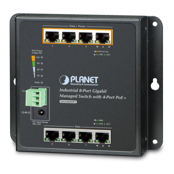
Industrial wall-mount managed gigabit ethernet switch
Hide thumbs
Also See for WGS-804HPT:
- Quick installation manual (30 pages) ,
- User manual (373 pages) ,
- User manual (359 pages)

Related Manuals for Planet WGS-804HPT


Summary of Contents for Planet WGS-804HPT
- Page 1 Industrial Wall-mount Managed Gigabit Ethernet Switch WGS-804HPT/WGS-4215-8T/WGS-4215-8T2S Quick Installation Guide...
-
Page 2: Table Of Contents
Table of Contents 1. Package Contents ..................3 2. Requirements ..................... 4 3. Wiring the Power Inputs ................5 3.1 Terminal Block Connector Pinout ............6 4. Installation ....................7 4.1 Wall Mount Installation ................. 7 4.2 Magnet Installation ................8 4.3 DIN-rail Mount Installation .............. -
Page 3: Package Contents
— In the following section, unless specified, the term “Wall-mount Managed Switch” mentioned in this quick installation guide refers to the WGS-804HPT / WGS-4215-8T / WGS-4215-8T2S. Open the box of the Wall-mount Managed Switch and carefully unpack it. The box... -
Page 4: Requirements
2. Requirements z Workstations running Windows XP/2003/Vista/7/8/2008/10, MAC OS X or later, Linux, UNIX, or other platforms are compatible with TCP/IP protocols. z Workstations are installed with Ethernet NIC (Network Interface Card) z Ethernet Port Connection Network cables -- Use standard network (UTP) cables with RJ45 connectors. ... -
Page 5: Wiring The Power Inputs
(Terminal block and DC jack) incorporated into customer’s automation network to enhance system reliability and uptime. Power Input Range 3-pin Terminal Block DC Jack Model WGS-804HPT 48~56V DC 48~56V DC WGS-4215-8T 12~48V DC, 24V AC 12~48V DC, 24V AC WGS-4215-8T2S... -
Page 6: Terminal Block Connector Pinout
3.1 Terminal Block Connector Pinout To install the 3-pin Terminal Block Connector on the Wall-mount Managed Switch, simply follow the following steps: Step 1: Insert positive DC power wire into V+, negative DC power wire into V-, and grounding wire into Ground. Ground Step 2: Tighten the wire-clamp screws for preventing the wires from loosening and plug into the Wall-mount Managed switch. -
Page 7: Installation
Step 1: There are 4 holes with 8mm diameter on the wall; the distance between the 2 holes is 133mm(WGS-804HPT/WGS-4215-8T), 163mm(WGS-4215- 8T2S) and the line through them must be horizontal. Step 2: Install a conductor pipe inside the board hole and flush the edge of the conductor pipe with the wall surface. -
Page 8: Magnet Installation
4.2 Magnet Installation To install the Wall-mount Managed Switch on a magnetic surface, simply follow the following diagram: 4.3 DIN-rail Mount Installation The DIN-rail kit is included in the package. When the wall-mount application for the Wall-mount Managed Switch needs to be replaced with DIN-rail application, please refer to the following figures to screw the DIN-rail on the Wall-mount Managed Switch. - Page 9 Step 2: Lightly insert the button of DIN-rail into the track Push Click Step 3: Check whether the DIN-rail is tightly on the track...
-
Page 10: Starting Web Management
5. Starting Web Management The following shows how to start up the Web Management of the Wall-mount Managed Switch. Note the Wall-mount Managed Switch is configured through an Ethernet connection. Please make sure the manager PC must be set to the same IP subnet address. - Page 11 Logging in to the Wall-mount Managed Switch 1. Use Internet Explorer 8.0 or above Web browser and enter IP address http://192.168.0.100 to access the Web interface. 2. When the following dialog box appears, please enter “admin” in both the default user name and password fields. The login screen in Figure 5-2 appears. Default Username: admin Default Password: admin Figure 5-2: Web Login Screen...
- Page 12 Figure 5-3: Web Main Screen of Wall-mount Managed Switch The Switch Menu on the left of the Web page lets you access all the commands and statistics the Wall-mount Managed Switch provides. Figure 5-4: Switch Menu Now, you can use the Web management interface to continue the Switch management.
-
Page 13: Saving Configuration Via The Web
6. Saving Configuration via the Web In the Wall-mount Managed Switch, the running configuration file stores in the RAM. In the current version, the running configuration sequence of running- config can be saved from the RAM to FLASH by “Save Configurations to FLASH” function, so that the running configuration sequence becomes the startup configuration file, which is called configuration save. -
Page 14: Recovering Back To Default Configuration
5 seconds. After the device is rebooted, you can login the Web interface management within the same subnet of 192.168.0.xx. Figure 7-1: WGS-804HPT/WGS-4215-8T Reset Button Figure 7-2: WGS-4215-8T2S Reset Button... -
Page 15: Customer Support
WGS-804HPT / WGS-4215-8T / WGS-4215-8T2S User’s Manual: http://www.planet.com.tw/en/support/download.php?type1=22153&model=&type=3 Copyright © PLANET Technology Corp. 2015. Contents are subject to revision without prior notice. PLANET is a registered trademark of PLANET Technology Corp. All other trademarks belong to their respective owners.
Need help?
Do you have a question about the WGS-804HPT and is the answer not in the manual?
Questions and answers