Advertisement
Quick Links
Please Read
L i g h t i n g Z o n e C o n t r o l l e r a n d
L i g h t i n g Z o n e C o n t r o l l e r P a n e l s
100-277 V
50/60 Hz
R
16 A Max.
Coopersburg, PA 18036 USA
www.lutron.com
®
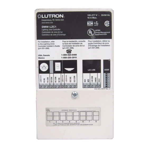
DMW-LZC1
Lighting Zone Controller
LISTED
Controlador de zona de luz
Energy Management
Contrôleur de zone d'Éclairage
Equipment 5C81
Para la instalación, consulte
Pour installation, référer au
For installation, refer
to the Lighting Zone
la Guía del Instalador de
guide Contrôleur de zone
d'Éclairage de l'installateur
Controller Installer's Guide
Controlador de zona de luz
(p/n 031-268).
(p/n 031-268).
(p/n 031-268).
1-800-523-9466
USA, Canada
Mexico
1-888-235-2910
®
LZC LINK
ADDR
1
2
3
4
5
6
7
8
9
10
11 12 13 14 15
P/N 500-9066 Rev. F
LZC1
Large
panel
Models Available
Model #
DMWP4-FT
DMW-LZC4
All models are rated at 50/60 Hz and up to 16 A per LZC.
DMWP4-FT is rated at 16 A total.
Installation and Maintenance Guide
Small
panel
# LZCs
Voltage
1
100-277 V
4
100-277 V
12
100-277 V
18
100-277 V
24
100-277 V
4
100-277 V
12
120 V
18
120 V
12
277 V
R
Contents
System Overview
Dimensions and Mounting
Wiring
Activating Loads in Bypass
Removing Bypass Jumpers
Addressing
Wiring the LZC Link
Installing Wall Controls
Mounting and Testing Wall Controls
Installing Occupant Sensors
Installing Daylight Sensors
Testing Wall Controls and Sensors
Scheduling System Commissioning
Appendix: Wiring Load Interfaces
Appendix: Emergency Mode
Appendix: Lamp Burn-In
Appendix: Voltage Map
Appendix: Troubleshooting
Warranty
Contact Information
Enclosure
Feed Type
Self-enclosed
N/A
Small panel
Feed-through
Standard panel
Feed-through
Standard panel
Feed-through
Standard panel
Feed-through
Small panel
Main lugs
Standard panel
Main lugs
Standard panel
Main lugs
Standard panel
Main lugs
2
5
9
16
17
18
20
21
23
24
25
26
26
27
30
35
36
37
39
40
Breakers
None
None
None
None
None
None
120 V
20 A
120 V
20 A
277 V
20 A
Advertisement

Subscribe to Our Youtube Channel
Related Manuals for Lutron Electronics DMW-LZC1

Summary of Contents for Lutron Electronics DMW-LZC1
-
Page 1: Table Of Contents
L i g h t i n g Z o n e C o n t r o l l e r P a n e l s Installation and Maintenance Guide 100-277 V 50/60 Hz 16 A Max. Coopersburg, PA 18036 USA www.lutron.com ® DMW-LZC1 Lighting Zone Controller LISTED Controlador de zona de luz Energy Management Contrôleur de zone d'Éclairage Equipment 5C81 Para la instalación, consulte Pour installation, référer au... - Page 2 1 LZC 7000P processor Lighting load panels One LZC link can contain a maximum of 63 LZCs Small LZC panel Individual LZC (DMW-LZC1) Standard LZC panel (not shown to scale) To Digital microWATT server or other GRAFIK 7000P...
- Page 3 This page applies to: System Overview (continued) Small Std. Panel Panel LZC1 Component Descriptions Lighting Zone Controllers (LZCs) are one component of an energy management and lighting control system. They can be used as part of a Digital microWATT (DMW) or GRAFIK 7000 system.
- Page 4 This page applies to: System Overview (continued) Small Std. Panel Panel LZC1 Wiring Detail This diagram shows all the connections that may be made to a lighting zone controller (LZC). Line voltage wiring to an LZC panel may vary slightly. The remainder of this Guide will explain this wiring in more detail. Load wiring Line voltage wiring...
-
Page 5: Dmw-Lzc1
This page applies to: Dimensions and Mounting LZC1 Mounting the LZC1 • Mount the DMW-LZC1 onto a 4 x 4 in. (102 x 102 mm) standard (1900) junction box (not included, but Dimensions are in inches (mm) available; Lutron part number 241-496). - Page 6 This page applies to: Dimensions and Mounting (continued) Small Panel Mounting the Small Panel Dimensions are in inches (mm) Knockouts are 7/8 inch (22 mm) in diameter Top View Knockout for LZC link wiring PELV (Class 2: USA) Knockout for main feed entry wiring only (panel with main lugs only) Left Side View...
- Page 7 This page applies to: Dimensions and Mounting (continued) Std. Panel Mounting the Standard Panel Dimensions are in inches (mm) Knockouts are 7/8 inch (22 mm) in diameter Top View Left Side View Front View Right Side View (24) conduit knockouts for input 0.31 (8) feeds (feed-through panel only), switch...
-
Page 8: Dmwp12-Ft
This page applies to: Dimensions and Mounting (continued) Std. Panel Mounting the Standard Panel Side View Front View Notes • Surface mount indoors • See panel weights below. Reinforce wall structure for weight and local codes • Ambient temperature: 32 °F-104 °F (0 °C-40 °C) Input feeds (feed-through... - Page 9 This page applies to: Wiring LZC1 Wiring the LZC1 in Bypass Bypass wiring is a TEMPORARY wiring scheme to test the dimming ballast wiring without using the LZC Danger! Locate and lock the supply breaker control. If there is a wiring problem or a short in the in the OFF position, or remove the supply circuit, this will prevent damage to the LZC.
- Page 10 • Remove the bypass wiring connections previously made. • Connect the input feed wires and the output load wires to the lighting zone controller as indicated in the wiring Note: Maximum wire length from DMW-LZC1 diagram below. to last dimming ballast is 750 feet (240 m).
- Page 11 This page applies to: Wiring (continued) Small Panel Small Panels: Conduit Entry Danger! Locate and lock the supply breaker in the OFF position, or remove the supply fuse before continuing. Small Panel with Main Lugs Small Feed-Through Panel Feed wiring Ground/earth Preferred feed wiring from distribution...
- Page 12 This page applies to: Wiring (continued) Std. Panel Standard Panels: Conduit Entry Danger! Locate and lock the supply breaker in the OFF position, or remove the supply fuse before continuing. Standard Panel with Main Lugs Standard Feed-Through Panel Feed wiring from distribution panel (typical for all circuits)
- Page 13 This page applies to: Wiring (continued) Small Std. Panel Panel Panel Wiring: General Notes See the following two pages for details on wiring loads to the small and standard panels. • The only dimmed loads that can be connected directly Wiring dimmed loads: to an LZC panel are fluorescent fixtures containing •...
- Page 14 Black Lutron 3-wire Red (SH1) Maximum wire dimming ballast Black (H1) length from Green Green/Yellow (G1) DMW-LZC1 to White (N1) White (N1) last dimming White ballast is 750 Fixture ground feet (240 m). Note: For switchable loads (non-dimming), make sure address switch 8 on the LZC is in the ON position.
- Page 15 Orange (DH1) Lutron 3-wire Maximum wire Black Red (SH1) dimming ballast Black (H1) length from Green Green/Yellow (G1) DMW-LZC1 to White (N1) last dimming White White (N1) Fixture ground ballast is 750 Orange (DH2) (do not use) Black Red (SH2) feet (240 m).
- Page 16 This page applies to: Activating Loads in Bypass Small Std. Panel Panel A. Complete load and feed wiring. See previous sections. AC RMS current B. Check that the bypass jumpers are in place. LZC 1 These jumpers protect from load faults and must Load circuit be used to check load wiring when it is installed wiring...
- Page 17 This page applies to: Removing Bypass Jumpers Small Std. Panel Panel A. After all load wiring has been checked, turn circuit breakers OFF. B. Use the tool provided to remove the bypass jumpers and store them for possible future use. (Removal is shown at right.) C.
- Page 18 If your system drawings are not clear, contact Lutron before installing. 100-277 V 50/60 Hz Coopersburg, PA 18036 USA 16 A Max. Coopersburg, PA 18036 USA DMW-LZC1 www.lutron.com Lighting Zone Controller ® DMW-LZC1 Controlador de zona de luz Contrôleur de zone d'Éclairage...
- Page 19 This page applies to: Addressing (continued) Small Std. Panel Panel LZC1 Address Switch Setting Chart Router Panel or GRAFIK 7000P Processor Panel Address: Link Number: Area Name or Description: Switch is up (ON) Switch is down (OFF) Make a copy of this page for each LZC link in your system. Place a check mark next to each unit address that is used on the link.
- Page 20 Lighting Zone Controller Integrated Lighting Automation System ® Controlador de zona de luz DMW-LZC1 LISTED DMW-LZC1 (Lighting Zone Controller) Contrôleur de zone d'Éclairage Lighting Zone Controller Energy Management LISTED LUTRON Controlador de zona de luz Coopersburg, P A 18036 ®...
- Page 21 Circuit Common 100-277 V 50/60 Hz Coopersburg, PA 18036 USA 16 A Max. To wall controls Coopersburg, PA 18036 USA WC Common DMW-LZC1 www.lutron.com Lighting Zone Controller ® Controlador de zona de luz DMW-LZC1 WC Signal Contrôleur de zone d'Éclairage...
- Page 22 +24 V PS Signal PS Common 100-277 V 50/60 Hz Coopersburg, PA 18036 USA 16 A Max. Circuit Common DMW-LZC1 Coopersburg, PA 18036 USA www.lutron.com Lighting Zone Controller ® To wall controls Controlador de zona de luz DMW-LZC1 WC Common Contrôleur de zone d'Éclairage...
- Page 23 This page applies to: Mounting and Testing Wall Controls Small Std. Panel Panel LZC1 Mounting Mount the wall controls using the supplied screws. Note: If the control is being mounted next to other controls, break off the side sections of the adjoining controls to allow them to fit.
- Page 24 PS Signal PS Common Circuit Common 100-277 V 50/60 Hz Coopersburg, PA 18036 USA WC Common 16 A Max. DMW-LZC1 Coopersburg, PA 18036 USA www.lutron.com Lighting Zone Controller ® WC Signal Controlador de zona de luz DMW-LZC1 Contrôleur de zone d'Éclairage...
- Page 25 PS Common Circuit Common 100-277 V 50/60 Hz Coopersburg, PA 18036 USA WC Common 16 A Max. DMW-LZC1 Coopersburg, PA 18036 USA www.lutron.com Lighting Zone Controller ® WC Signal Controlador de zona de luz DMW-LZC1 Contrôleur de zone d'Éclairage...
- Page 26 This page applies to: Testing Wall Controls and Sensors Small Std. Panel Panel LZC1 Provided that all lighting zone controllers have been on for at least 100 hours, and the emergency contact closure is present, the wall controls, occupant sensors, Danger! Turning ON power to the lighting zone and daylight sensors can be tested.
- Page 27 This page applies to: Appendix: Wiring Load Interfaces Small Std. Panel Panel LZC1 Wiring the LZC in Bypass when Using Load Interfaces Danger! Locate and lock the supply breaker in Caution! The FDI-FTU-16A-120 and the FDI- the OFF position, or remove the supply fuse INC-2000 both operate on 120 V only.
- Page 28 FDI-FTU-16A-120 100-277 V 50/60 Hz 16 A Max. Neutral Coopersburg, PA 18036 USA www.lutron.com ® Tu-Wire ballast DMW-LZC1 ® Lighting Zone Controller LISTED Controlador de zona de luz Energy Management Contrôleur de zone d'Éclairage Equipment 5C81 interface Hot (120 V Pour installation, référer au...
- Page 29 FDI-INC-2000 100-277 V 50/60 Hz 16 A Max. Neutral Incandescent/magnetic Coopersburg, PA 18036 USA www.lutron.com ® DMW-LZC1 low-voltage interface Lighting Zone Controller LISTED Controlador de zona de luz Energy Management Contrôleur de zone d'Éclairage Equipment 5C81 Hot (120 V Pour installation, référer au For installation, refer Para la instalación, consulte...
- Page 30 This page applies to: Appendix: Emergency Mode Small Std. Panel Panel LZC1 Emergency mode with the Lighting Automation System Overview Electrical and construction codes typically require that certain circuits of lights be dedicated as emergency circuits in a commercial, occupied building. One method to accomplish this is to use battery powered fluorescent ballasts that turn lamps on when normal power is lost.
- Page 31 GRAFIK 7000P processor panel 100-277 V 50/60 Hz 16 A Max. Coopersburg, PA 18036 USA www.lutron.com ® DMW-LZC1 Lighting Zone Controller LISTED Controlador de zona de luz Energy Management Contrôleur de zone d'Éclairage Equipment 5C81 For installation, refer Para la instalación, consulte Pour installation, référer au...
- Page 32 S1 switches but they have to be in series with the first • Each switch must not be shared with any other switch. equipment. • Dry contact closures are not supplied by Lutron. DMW-LZC1 DMW-LZC1 DMW-LZC1 DMW- 100-277 V 50/60 Hz...
- Page 33 This page applies to: Appendix: Emergency Mode (continued) Small Std. Panel Panel LZC1 Wiring Method Two (continued) Switch S1: Entire system will go into emergency mode when switch S1 is open. GRAFIK 7000 System Digital microWATT System NTOMX-45J NTOMX-62J 4 3 2 1 4 3 2 1 (used only if UI link is connected...
- Page 34 This page applies to: Appendix: Emergency Mode (continued) Small Std. Panel Panel LZC1 Wiring Method Two (continued) Switch S3: Each lighting zone controller on Link 3 will enter emergency mode. Lighting zone controllers on other Digital microWATT router panels or GRAFIK 7000P processor panels, or on Links 1 or 2 of the same panel, will not be affected.
- Page 35 This page applies to: Appendix: Lamp Burn-In Small Std. Panel Panel LZC1 Burn-in New Lamps New lamps must be burned-in (seasoned) at full intensity for 100 hours before dimming for extended periods. Be sure wall controls are set to full for the first 100 hours or place the lighting zone controller into burn-in mode.
- Page 36 14.1-16.2 V 21-26.6 V 100-277 V 50/60 Hz 16 A Max. Coopersburg, PA 18036 USA www.lutron.com ® DMW-LZC1 Lighting Zone Controller LISTED Controlador de zona de luz Energy Management Contrôleur de zone d'Éclairage Equipment 5C81 Para la instalación, consulte Pour installation, référer au For installation, refer guide Contrôleur de zone...
- Page 37 This page applies to: Appendix: Troubleshooting Small Std. Panel Panel LZC1 Symptom Possible Cause Solution Lights are always OFF— • Power is OFF. Verify breaker is ON. there is no glow at the • System miswired. Check system wiring, connection of socket lamp ends, and no wires.
- Page 38 This page applies to: Appendix: Troubleshooting (continued) Small Std. Panel Panel LZC1 Symptom Possible Cause Solution Lights go to full, but not all the • Ballasts not properly grounded. Check that the fixture is properly grounded and way to minimum. that a ground plane is 1/2 in.
- Page 39 Lutron, the sunburst logo, GRAFIK Eye, Tu-Wire, Hi-Lume, Vareo, and NovaT* are registered trademarks; Digital microWATT, Eco-10, eLumen, and GRAFIK systems are trademarks of Lutron Electronics Co., Inc. © 2006 Lutron Electronics Co., Inc. Installation Guide for Lighting Zone Controllers...
- Page 40 FAX +33.(0)1.41.05.01.80 No. 16 Kowa Building, 4F, 1-9-20 FREEPHONE 0800.90.12.18 Akasaka, Minato-ku, Tokyo 107-0052 Japan Germany TEL +81.3.5575.8411 Lutron Electronics GmbH, Landsberger Allee 201, 13055 Berlin, Germany FAX +81.3.5575.8420 TEL +49.(0)30.9710.4590 FREEPHONE 0120.083.417 FAX +49.(0)30.9710.4591 Asia Technical Hotlines FREEPHONE 00800.5887.6635 Northern China: 10.800.712.1536...
Need help?
Do you have a question about the DMW-LZC1 and is the answer not in the manual?
Questions and answers