Simplex 4009 Manual
Nac power extender
Hide thumbs
Also See for 4009:
- Installation instructions manual (21 pages) ,
- Operation reference (8 pages) ,
- Installation manual (48 pages)
Advertisement
Quick Links
Cautions and Warnings
Introduction
© 1997 Simplex Time Recorder Co., Gardner, MA 01441-0001 USA
All specifications and other information shown were current as of publication, and are subject to change without notice
Technical Manuals Online! - http://www.tech-man.com
DO NOT INSTALL ANY SIMPLEX PRODUCT THAT APPEARS
DAMAGED. Upon unpacking your Simplex product, inspect the contents of the
carton for shipping damage. If damage is apparent, immediately file a claim
with the carrier and notify Simplex.
ELECTRICAL HAZARD - Disconnect electrical power when making any
internal adjustments or repairs. Servicing should be performed by qualified
Simplex Representatives.
STATIC HAZARD - Static electricity can damage components. Therefore,
handle as follows:
1.
Ground yourself before opening or installing components.
2.
Keep component wrapped in anti-static material at all times.
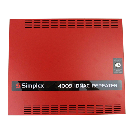
The Simplex 4009 NAC Power Extender (Figure 1) provides additional DC
signaling capacity to a Fire Alarm Control Panel (FACP) with a reverse polarity
Notification Appliance Circuit (NAC). The 4009 is UL-listed, electrically-
supervised, and protected against brown-out conditions and loss of primary AC
power.
4009
NAC POWER EXTENDER
Figure 1. Simplex 4009 NAC Power Extender
Continued on next page
574-827
Rev. B
Advertisement

Related Manuals for Simplex 4009


Summary of Contents for Simplex 4009
- Page 1 Keep component wrapped in anti-static material at all times. Introduction The Simplex 4009 NAC Power Extender (Figure 1) provides additional DC signaling capacity to a Fire Alarm Control Panel (FACP) with a reverse polarity Notification Appliance Circuit (NAC). The 4009 is UL-listed, electrically- supervised, and protected against brown-out conditions and loss of primary AC power.
-
Page 2: Hardware Components
565-558 Earth Detect Card 565-367 or 565-488 POWER SUPPLY If the 4009 is used with a 4001 system, adequate power from the host FACP may not be available for the NACs and system use. The power supply used in the 4009 is a linear supply with brownout and battery charger features. -
Page 3: System Configuration
A functional block diagram depicting the interconnections between modules is shown in Figure 2. Alarm signal and 0V connections provide alarm and trouble operation. The host FACP can detect EARTH faults on any NAC wiring from the signal card. 0V CONNECTION BETWEEN HOST AND 4009 SEE NOTE FIELD WIRING... - Page 4 When using 565-386 or 565-388 signal cards the alarm input from the host Alarm Input NAC must be 20 to 32 volts DC, with a maximum ripple voltage of 2 volts peak- Requirements to-peak. When using 565-545 or 565-569 signal cards the alarm input from the host NAC must be 18 to 32 volts DC, unfiltered power supplies can be used.
-
Page 5: System Installation
NAC Power Extender systems. Be sure that you are thoroughly familiar with this material before installing your 4009. To help you with installation of this and other Simplex equipment, the following publication is available for general reference: How to Wire a Building for a Fire Alarm System. - Page 6 System Installation, Continued Installation Checklist The installation checklist (shown in Table 1) provides a systematic method for installing the 4009. When you finish a procedural step, place a check mark in the appropriate box in the left column. Table 1. Installation Checklist PROCEDURE 1.
- Page 7 Simplex Branch Office. Use the following procedure when mounting a 4009. Carefully open the shipping container. Remove the 4009 from the shipping container and lay the unit on a flat surface. Unlock and open the panel door. Remove the knockout plugs on the back box for wire entry.
- Page 8 Wiring the 4009 When wiring the 4009, refer to the 841-925 Field Wiring Diagram, the Wiring Information mounted on the inside of the 4009 panel door, the 4009 NAC Power Extender Connection Diagram (Figure 4), and the following system wiring requirements.
- Page 9 Line Resistors used in the installation. Refer to the 841-925 Field Wiring Diagram and the procedure listed below when installing the 4009 peripheral devices. Determine the mounting locations of the peripheral devices and install system wires from the mounting location of each peripheral device to the 565-386 or 565-569 Style Y (Class B) Signal Card or the 565-388 or 565- 545 Style Z (Class A) Signal Card.
- Page 10 Connect external NACs to TB1-1 (SIG +) and TB1-2 (SIG -) on the first Signal Card. Install jumper in position 2-3 of P3 on the first 4009 Signal Card, install jumper in position 1-2 of P3 if used with 4003 (Assemblies 565-360, 565- 386, 565-388, 565-545, 565-569).
- Page 11 Jumper Placements and When 565-558 Earth Detect Module is not used, and on non-isolated Terminal Connections systems, install an 12 AWG copper wire from TB2-3 on the 565-367 and (continued) 565-488 power supply to 0V on the battery block of the host FACP. Apply system power.
- Page 12 574-827 Rev. B Technical Manuals Online! - http://www.tech-man.com...
Need help?
Do you have a question about the 4009 and is the answer not in the manual?
Questions and answers