Advertisement
Quick Links
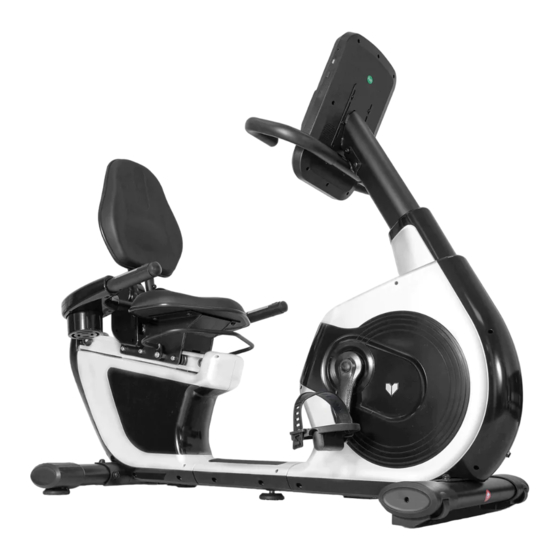
Commercial Recumbent Bike
Read all instructions carefully before using this product.
Retain this owner's manual for future reference.
IMPORTANT
All nuts and bolts are to be checked and tightened on a regular basis. This includes pedals and
other moving parts. Failure to do so may cause damage to your threads and void your warranty.
NOTE:
Product may vary slightly from the item pictured due to model upgrades. This manual may be subject to updates or changes.
Up to date manuals are available through our website at www.lifespanfitness.com.au
RBX-100
USER MANUAL
Advertisement

Related Manuals for LifeSpan RBX-100


Summary of Contents for LifeSpan RBX-100
- Page 1 RBX-100 Commercial Recumbent Bike USER MANUAL Read all instructions carefully before using this product. Retain this owner’s manual for future reference. IMPORTANT All nuts and bolts are to be checked and tightened on a regular basis. This includes pedals and other moving parts.
-
Page 2: Table Of Contents
TABLE OF CONTENTS Important Safety Instructions ....... 03 II. Care Instructions ..........04 III. -
Page 3: Important Safety Instructions
I. IMPORTANT SAFETY INSTRUCTIONS WARNING: Read all instructions before using this machine. Note the following precaution before assembling and operating the machine. • Assemble the machine exactly as the descriptions in the instruction manual. • Check all the bolts, nuts, and other connections before using the machine for the first time to ensure the machine is in the safe condition. -
Page 4: Care Instructions
II. CARE INSTRUCTIONS • All nuts and bolts are to be checked and tightened on a regular basis. This includes pedals and other moving parts. Failure to do so may cause damage to your thread and void your warranty. • Lubricate moving joints with grease after periods of usage. •... -
Page 5: Exploded Diagram
III. EXPLODED DIAGRAM EXPLODED DIAGRAM |... -
Page 6: Parts List
IV. PARTS LIST Part No. Description Part No. Description Main frame Handlebar post cover Handlebar post Flat washer D4 Handlebar Bottom tube end cap Seat slider Front left &right end cap 28L/R Handlebar connection Cross pan screw M4*10 Adjustable handlebar 30L/R Left &... -
Page 7: Assembly Instructions
V. ASSEMBLY INSTRUCTIONS Attention: Please follow these assembly instructions step by step to assemble this bike. 18 15 STEP 1 1. First, take off the Tube for package (42), inner hex screw (11), spring washer (15) and flat washer (19) from main frame (1). - Page 8 STEP 2 1. Install the Pedal (37L/R) to the Crank (21L/R) respectively. Note: Secure the Left Pedal (37L) Anticlockwise and the Right Pedal (37R) Clockwise as shown. Please make sure that the Pedal (37L/R) have been locked tightly before exercise. | ASSEMBLY INSTRUCTIONS...
- Page 9 STEP 3 1. First, sleeve the handlebar post cover (25) into handlebar post (2). Then connect extension wire 1 (47) and extension wire 2 (48), sensor extension wire (44) and sensor wire (43). 2. Lock handlebar post (2) to the post of main frame (1) with inner hex screw (12), spring washer (16), arc washer (17) and flat washer (20).
- Page 10 STEP 4 1. Fix handlebar (3) to the handlebar post (2) with inner hex screw (12), spring washer (16) and flat washer (20). 2. Connect extension wire 2 (48), sensor extension wire (44) and the wire of console (39). Then lock the console (39) to handlebar post (2) with cross pan screw (29), and flat washer (26).
- Page 11 20 16 STEP 5 1. Lock left & right seat cover (32L/R) to the seat slider (4) with cross pan screw (13). 2. First, connect handle pulse (46) and extension wire 1 (47). Then fix handlebar connection (5) to seat slider (4) with inner hex screw (12), spring washer (16) and flat washer (20). 3.
- Page 12 STEP 6 1. Firstly, lock the seat (35) to seat slider (4) tightly with inner hex screw (12) and flat washer (20). 2. Insert back bracket (10) into the connection axle of seat slider (4). Then, lock the back bracket (10) tightly with inner hex screw (12) and arc washer (17).
-
Page 13: Exercise Guide
VI. COMPUTER OPERATION DISPLAY FUNCTION ITEM DESCRIPTION Count up - No preset target, Time will count up from 00:00 to maximum 99:59 with each increment is 1 minute. TIME Count down - If training with preset Time, Time will count down from preset to 00:00. Each preset increment or decrement is 1 minute between 00:00 to 99:00. - Page 14 OPERATION PROCEDURE POWER ON Plug in power supply, computer will power on and display all segments on LCD for 2 seconds (Drawing 1). Drawing 1 Then enter into User data setting. Use UP or DOWN (Encoder) to select U1~U4, then set SEX, AGE, HEIGHT (Drawing 2), WEIGHT and confirm by pressing MODE/ENTER key.
- Page 15 MANUAL MODE Press START in main menu may start workout in manual mode directly. 1. Use UP or DOWN (Encoder) to select workout program, choose M and press MODE / ENTER to select. 2. Use UP or DOWN (Encoder) to adjust load level (Drawing 4), preset value 1. 3.
- Page 16 PROGRAM MODE 1. Use UP or DOWN (Encoder) to select workout Program, choose P01 ,P02, P03-P12, and press MODE / ENTER to select. 2. Use UP or DOWN (Encoder) to adjust load level (Drawing 10), preset value 1. 3. Use UP or DOWN (Encoder) to set TIME. 4.
- Page 17 WATT MODE 1. Use UP or DOWN (Encoder) to select workout program, choose W and press MODE / ENTER to select. 2. Use UP or DOWN (Encoder) to set WATT target. (default: 120, Drawing 15). 3. Use UP or DOWN (Encoder) to set TIME. 4.
- Page 18 RECOVERY After exercising for a period, keep holding on hand grips or wearing chest strap and press RECOVERY key. All function display will stop except "TIME" starts counting down from 00:60 to 00:00 (Drawing 17). Screen will display your heart rate recovery status with the F1, F2 to F6 (Drawing 18). F1 is the best, F6 is the worst. User may keep exercising to improve the heart rate recovery status.
- Page 19 BODY FAT 1. In STOP mode, press the BODY FAT key to start body fat measurement. 2. Console will display UX (Drawing 19) and start measuring (Drawing 20~21). 3. During measuring, users have to hold both hands on the hand grips. When console detect the pulse, LCD display as (Drawing 22) for 8 seconds until computer finish measuring.
- Page 20 Drawing 23 Drawing 24 Drawing 25 Note: 1. After 4 minutes without pedaling or pulse input, console will enter into power saving mode. Press any key may wake the console up. 2. When computer act abnormal, please plug out the adaptor and plug in again. | COMPUTER OPERATION...
-
Page 21: Computer Operation
VI. EXERCISE GUIDE PLEASE NOTE: Before beginning any exercise program, consult your physician. This is important especially if you are over the age of 45 or individuals with pre-existing health problems. The pulse sensors are not medical devices. Various factors, including the user’s movement, may affect the accuracy of heart rate readings. - Page 22 COOL DOWN Finish each workout with a light jog or walk for at least 1 minute. Then complete 5 to 10 minutes of stretching to cool down. This will increase the flexibility of your muscles and will help prevent post- exercise problems.
-
Page 23: Warranty
Any claim against this warranty must be made through your original place of purchase. Proof of purchase is required before a warranty claim may be processed. If you have purchased this product from the Official Lifespan Fitness website, please visit https://lifespanfitness.com.au/warranty-form For support outside of warranty, if you wish to purchase replacement parts or request a repair or service, please visit https://lifespanfitness.com.au/warranty-form and fill in our Repair/Service... - Page 24 WWW.L IF ESPAN F ITNE S S . COM . A U...
Need help?
Do you have a question about the RBX-100 and is the answer not in the manual?
Questions and answers