Table of Contents
Advertisement
Quick Links
Advertisement
Table of Contents

Related Manuals for Bartec SILASPZ


Summary of Contents for Bartec SILASPZ
- Page 1 Manual Ex p Control Unit SILAS...
- Page 2 Ex p Control unit SILAS , Type A7-37S2-2111/*520 Stainless steel version ATEX / IECEx Zone 2 / 22 Document number: A1-37S2-7D0001 Revision: 0 Order code: 413915 BARTEC GmbH Phone: +49 7931 597-0 Support: info@bartec.de Max-Eyth-Straße 16 Fax: +49 7931 597-480 Internet: www.bartec.de...
- Page 3 Page 2 of 88 A1-37S2-7D0001_pz_Manual_Exp-Control-Unit_20210923_0_en.docx Rev. 0...
-
Page 4: Table Of Contents
Ex p Control unit Table of contents SILAS 0 Table of contents Table of contents ......................3 About these operating instructions ................7 Highlighting in the document ..................8 Warnings ........................8 Symbols and icons ......................9 Technical changes ......................9 Languages ........................ - Page 5 Ex p Control unit Table of contents SILAS Product description ....................16 General information ..................... 16 Ex p control units SILAS ....................16 SILAS design, type A7-37S2-2111/*520 ............... 17 Accessories ........................18 Valve fuse ........................18 Pressure outlet ......................18 Purge gas valve ......................
- Page 6 Ex p Control unit Table of contents SILAS Operation ......................... 48 WEB interface ......................48 Adjusting the LAN connection ..................48 Operation of the WEB interface ..................50 Logging onto the WEB interface ..................50 Navigation in the WEB interface ................... 50 Input of parameters......................
- Page 7 Ex p Control unit Table of contents SILAS Maintenance and care ....................77 Types of purging gas ..................... 77 Maintenance work ......................77 Maintenance intervals ....................77 Visual inspection ......................78 Cleaning ........................78 Regular maintenance ....................78 Repairs ......................... 78 Faults and troubleshooting ..................
-
Page 8: About These Operating Instructions
Should you require further information, please request the required information from your local or responsible BARTEC branch. Read the operating instructions and in particular the safety instructions carefully before using the device. -
Page 9: Highlighting In The Document
Ex p Control unit About these operating instructions SILAS Highlighting in the document Warnings Warnings are used in this user manual to warn of property damage and personal injury. Always read and follow these warnings. Warnings are specially highlighted in this user manual and identified by symbols: DANGER DANGER indicates a hazardous situation which, if safety measures are not observed, may result in death or serious injuries with permanent damage. -
Page 10: Symbols And Icons
The original user manual is written in German. All other available languages are translations of the original user manual. The user manual is available in German and English. If further languages are required, these must be requested from BARTEC or stated when placing the order. Rev. 0 A1-37S2-7D0001_pz_Manual_Exp-Control-Unit_20210923_0_en.docx... -
Page 11: Safety
Ex p Control unit Safety SILAS 2 Safety Intended use Exclusive purpose The Ex p control unit SILAS serves exclusively as a controlling and monitoring device for pressurized enclosures and is intended for use in explosion group II, category 2GD (EPL Gb and EPL Db) and temperature class T4 or T5 or for use in dusty environments with surface temperatures of T95 °C or T130 °C. -
Page 12: Safety Instructions
Please observe the national waste disposal regulations for disposal. Servicing Regular servicing is not necessary if the device is operated correctly in accordance with the installation instructions and ambient conditions. BARTEC recommends annual servicing and inspection. See Chapter “Maintenance and care”. Rev. 0 A1-37S2-7D0001_pz_Manual_Exp-Control-Unit_20210923_0_en.docx... -
Page 13: Avoidance Of Damage To Property
Ex p Control unit Safety SILAS Repairs Only authorized persons working in accordance with the latest development in technology and using original spare parts may do repairs on explosion-protected equipment. The applicable provisions must be observed. Repairs must be carried out in accordance with EN / IEC 60079-19 / ГОСТ... -
Page 14: Aggressive Cleaning Agents
Ex p Control unit Safety SILAS Aggressive cleaning agents When selecting the correct cleaning agent, it is essential that it is suitable for use since otherwise damage may occur to seals and connections. Combustible products are generally not permitted. Danger to health due to improper disposal According to the European WEEE Directive, electrical and electronic equipment may not be disposed of with household waste. -
Page 15: Marking And Test Certificate
Ex p Control unit Safety SILAS Marking and test certificate The Ex p control unit is approved for the following areas. Ex p control unit SILAS, type A7-37S2-2111/*520 ATEX (Europe) II 3G Ex ec mc ic [ic pzc] IIC T5/T4 Gb Marking II 3D Ex tc [ic pzc] IIIC T130 °C / T95 °C Db BVS 19 ATEX E 016 X... - Page 16 Ex p Control unit Safety SILAS Standard Designation Explosive atmospheres - Part 31: EN 60079-31:2014 Equipment dust ignition protection by enclosure IEC 60079-31:2013 Edition: 2.0 “t” ГОСТ IEC 60079-31-2013 Safety requirements for electrical equipment for EN 61010-1:2010 measurement, control and laboratory use – Part 1: IEC 61010-1:2010 Edition 3.0 General requirements EN 61000-6-4:2007 + A1:2011...
-
Page 17: Product Description
Ex p Control unit Product description SILAS 3 Product description General information The Ex p type of protection, referred to as “pressurized enclosure”, is based on the measure of purging out any explosive gases that are in a closed enclosure and then generating and maintaining a level of pressure that is higher than that of the ambient atmosphere. -
Page 18: Silas Design, Type A7-37S2-2111/*520
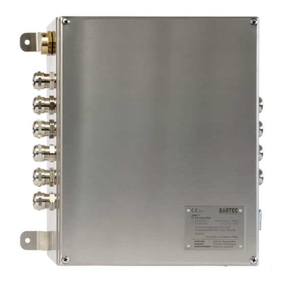
Ex p Control unit Product description SILAS SILAS design, type A7-37S2-2111/*520 The enclosure of variant two is available for the Ex p control unit SILAS and is made of stainless steel. In this enclosure variant, the associated pressure measurement card is integrated. Ex p control units of this enclosure variant can be mounted internally or externally on the pressurized enclosure. -
Page 19: Accessories
Ex p Control unit Product description SILAS Accessories Valve fuse Valve fuse, type 05-0080-10** The valve fuse serves to secure the connected purging gas valve and is connected on the Ex e board of the control unit. Pressure outlet Pressure outlet, Type 17-51P3-1604 The pressure outlet serves as a pressure relief valve for Ex pzc systems Purge gas valve... -
Page 20: Programming Switch
Ex p Control unit Product description SILAS Programming switch The programming switch must be connected to the control unit in order to change parameters and switching values. The control unit SILAS does not accept values, which are changed without an active connected programming switch. Programming cable The programming cable is used to connect the Ex p control unit to the PC. -
Page 21: Transport And Storage
4 Transport and storage Scope of delivery Missing parts or damage must be reported immediately in writing to the forwarding agent, the insurance company or BARTEC GmbH. Check the completeness of the scope of delivery using the delivery note. As standard, each Ex p control unit is delivered with the following scope of... -
Page 22: Storage
Ex p Control unit Transport and storage SILAS Storage Store the control unit in a horizontal position and at a temperature of -25 °C to +60 °C in its original packaging. The environment must be dry, dust-free and low vibration. Store the control unit for a maximum of 2 years. -
Page 23: Installation
Ex p Control unit Installation SILAS 5 Installation Before starting work, find out about the general safety instructions (see Chapter 2 Safety instructions). Deviations in the installation of customer-specific assemblies may occur. Observe the chapters Installation and Electrical connections. Carry out the installation according to the following sections, unless otherwise agreed for customer-specific control units. -
Page 24: Assembly "Internal Mounting Kit, Type 05-0091-0275
Ex p Control unit Installation SILAS Assembly "Internal mounting kit, type 05-0091-0275" Mounting the atmosphere measuring point when mounting the Ex p control unit inside the protected equipment Procedure: Make a 16.5mm diameter bore hole at the intended location on the pressurized enclosure. -
Page 25: Assembly "External Mounting Kit, Type 05-0091-0280
Ex p Control unit Installation SILAS Assembly "External mounting kit, type 05-0091-0280" For external mounting of the Ex p control unit, the two measuring points must be routed into the Ex p control cabinet using the "External" mounting kit. Procedure: ... -
Page 26: Installation Purging Gas Supply
Ex p Control unit Installation SILAS Installation purging gas supply ATTENTION MATERIAL DAMAGE CAUSED BY THE ABSENCE OF A PURGE GAS NOZZLE. Due to the build-up of internal pressure, there is a risk of excessive strain on the pressurized enclosure. ... -
Page 27: Version G1/4
Ex p Control unit Installation SILAS Version G1/4” The G1/4" purge gas supply is applicable up to a protected volume of 300 liters. The assembly of the purging gas supply must be installed carefully. To ensure that the screwed parts are tight, they can be sealed by means of a Teflon® tape. Care must be taken to prevent the penetration of foreign particles during assembly. -
Page 28: Version G1/2
Ex p Control unit Installation SILAS Version G1/2” The G1/2" purge gas supply version is applicable up to a protected volume of > 300 liters. The assembly of the purging gas supply must be installed carefully. To ensure that the screwed parts are tight, they can be sealed by means of a Teflon® tape. Care must be taken to prevent the penetration of foreign particles during assembly. -
Page 29: Version G1/4" (Dust Application)
Ex p Control unit Installation SILAS Version G1/4” (Dust application) For dust applications, there is no purge phase in a pressurized enclosure and only positive overpressure is applied. Therefore, no purge gas valve is present. The assembly of the purging gas supply must be installed carefully. To ensure that the screwed parts are tight, they can be sealed by means of a Teflon®... -
Page 30: Pneumatic Connections
Ex p Control unit Installation SILAS Pneumatic Connections Pneumatic connections SILAS, type A7-37S2-2111/*520 Installation inside Ex p equipment When installing the controller inside the pressurized equipment, the atmospheric connection must be routed to the outside. Please use the assembly kit for the atmospheric connection here. The adaption pressure measurement card comes with two quick hose connections as standard. -
Page 31: Typical Arrangement - Outside Installation / Gas Application
Ex p Control unit Installation SILAS Typical arrangement - outside installation / gas application The following figures show the installation of the SILAS control unit with one or two pressure outlet modules. The Ex p control unit is mounted outside the Ex p equipment. -
Page 32: Typical Arrangement - Inside Installation / Gas Application
Installation SILAS Typical arrangement - inside installation / gas application The following figures show the mounting of the SILASpz control unit with one or two pressure outputs. The Ex p control unit is mounted inside the Ex p equipment. Position... -
Page 33: Typical Arrangement - Outside Installation / Dust Application
Ex p Control unit Installation SILAS Typical arrangement - outside installation / dust application The following figures show the installation of the SILAS control unit with one or two pressure outlet modules. The Ex p control unit is mounted outside the Ex p equipment. -
Page 34: Typical Arrangement - Inside Installation / Dust Application
Installation SILAS Typical arrangement - inside installation / dust application The following figures show the mounting of the SILASpz control unit with one or two pressure outputs. The Ex p control unit is mounted inside the Ex p equipment. Position... -
Page 35: Electrical Connections
Ex p Control unit Electrical connections SILAS 6 Electrical connections DANGER DEATH OR SERIOUS PHYSICAL INJURY DUE TO WORK ON LIVE PARTS. Fatal injury from electrical current. Observe the five safety rules for work on electrical systems: Disconnect mains; protect against unintended reconnection; verify the absence of voltage;... -
Page 36: General
Ex p Control unit Electrical connections SILAS General Connection notes DANGER DEATH OR SERIOUS PHYSICAL INJURY WHEN THE COVER OF THE CONTROL UNIT SILAS IS OPENED IN AN EXPLOSIVE ATMOSPHERE. Risk of explosion. Before opening the lid of the enclosure, check the atmosphere for any explosive gases. -
Page 37: Emc-Compliant Connection
EMC Directive. BARTEC Ex p control units can only operate safely and trouble free with an EMC- compliant wiring. This chapter supports you in the EMC-compliant design of your system. -
Page 38: Pre-Fuse
Ex p Control unit Electrical connections SILAS Earthing cables The earthing of a system satisfies protective and functional measures. Please observe the following points: Earthing cables should be as short as possible. Avoid ground loops. Use ground straps with a width of at least 10 mm. Shielding In order to ensure trouble free operation of a system, cables with the largest possible surface area (not cross section) are important. -
Page 39: Inductive Loads
VDR resistor is exploited to become low-resistance above a certain threshold voltage. This short-circuits the self-induction voltage. Any oscillation that arises is damped by the RC snubber. Interference suppression measure, e.g. BARTEC 07-7311-93GU/K000 RC snubber Varistor Protective circuit for DC supplied inductive loads This circuit variant is used for DC-powered relays / contactors. -
Page 40: Electrical Wiring Silas
Ex p Control unit Electrical connections SILAS Electrical wiring SILAS Rev. 0 A1-37S2-7D0001_pz_Manual_Exp-Control-Unit_20210923_0_en.docx Page 39 of 88... -
Page 41: Ex E" Connection Terminals
Ex p Control unit Electrical connections SILAS “Ex e” connection terminals Terminal row “X3” ATTENTION MATERIAL DAMAGE DUE TO INCORRECT SUPPLY VOLTAGE. Internal electronics of the Ex p control unit can be destroyed. Before activating the supply voltage, compare the value of the supply voltage with the printed value of the control unit. - Page 42 Ex p Control unit Electrical connections SILAS Terminal row “X5” The Ex p control unit has one floating changeover contact K3 and one floating changeover contact K4 for signaling and processing signals. The associated switching function can be set in the Ex p control unit via the WEB interface and is freely programmable.
- Page 43 Ex p Control unit Electrical connections SILAS Terminal row “X12” Floating signaling K2 can be classified as pure enable. A floating signal (4x NO) is available on the Ex p control unit. This signal can either be used as an enable that is also safety related.
- Page 44 Ex p Control unit Electrical connections SILAS Terminal row “X6” The terminal row X6 is used to connect the LAN connection cable. Terminal Connection Function Not used Not used Not used Not used Connection of the original programming cable Send, negative GNWH Send, positive Receive, negative...
-
Page 45: Connection Terminals "Ex I
Ex p Control unit Electrical connections SILAS Connection terminals “Ex i” Terminal row “X9” DANGER DEATH OR SERIOUS PHYSICAL INJURY DUE TO COMMISSIONING WITH BYPASS KEY SWITCH IN POTENTIALLY EXPLOSIVE ATMOSPHERE. Risk of explosion. Have the commissioning with a bypass key switch approved by the factory manager or his representative. - Page 46 Ex p Control unit Electrical connections SILAS For the bypass switch to be detected and the function to be executed, a resistor with 620 Ω must be connected to the closing contact. The temperature sensor can be a PT 100 or 1000.
- Page 47 After changing or adapting parameters, a final function test must be performed. During normal operation of the Ex p system it may not be connected. The BARTEC parameter-setting switch must be used to change the parameters. The temperature sensor can be a PT 100 or 1000.
- Page 48 Ex p Control unit Electrical connections SILAS Terminal row “X17” The optionally available p operator panel can be connected to the terminal row “X17”. Terminal Connection Wire Function 3V3V_HMI Power supply Ground connection HMI_RX Data cable HMI_TX Data cable Terminal row – measurement card The pressure sensor board belonging to the Ex p control unit is connected to the terminal row (screw connection).
-
Page 49: Operation
Ex p Control unit Operation SILAS 7 Operation Operation of the Ex p control unit for end users is described in the following chapters. A description of the configuration and settings is provided in separate operating instructions. The complete solution starts automatically after connecting the purge gas supply and the supply voltage. - Page 50 Ex p Control unit Operation SILAS Procedure: Open the network settings for the LAN interface on the PC/laptop. Select the properties of the LAN connection by pressing the “Properties” button. Open the network adapter settings using the “Configure…” button and select Advanced. Select the “Speed &...
-
Page 51: Operation Of The Web Interface
Ex p Control unit Operation SILAS Operation of the WEB interface The web interface is operated using the input devices on the PC. Logging onto the WEB interface Two login levels are available on the WEB interface Level 1 Guest access User ID guest Password... -
Page 52: Input Of Parameters
Ex p Control unit Operation SILAS Input of parameters Changing parameters in the Web interface must be carried out in a certain sequence: Procedure for changing parameters: Activate the parameter setting switch. Logging in to the web interface If you are already logged in, the web interface requires a new log-in. -
Page 53: Menu Structure Web-Interface
Ex p Control unit Operation SILAS Menu structure WEB-Interface The WEB interface integrated in the Ex p control unit shows the following menu structure: Ex p Parameter Purge parameter Purge modi Pressure parameter Characterisitic Enclosure parameter Start page Info Status Messages File Parameter... -
Page 54: Web-Interface Operating Menu
Ex p Control unit Operation SILAS WEB-Interface operating menu Purge parameter The "Ex p parameter / Purge parameter" menu contains the purge parameters. This includes the submenus Purge mode, Pressure parameter, Characteristics and enclosure parameters. Purge mode The Ex p sequence control is defined in the "Purge mode" submenu. Manuel / Automatic = Determines whether the Ex p control unit performs purging with a fixed stored... - Page 55 Ex p Control unit Operation SILAS Purge programs gas application: Functions Purge time starts Purge time stops Ex p Purge Ex p active when p3 is when p5 is inactive phase after exceeded reached after Expiration po < p1 Ex_p_1 purge time po >...
- Page 56 For automatic purge time determination, the characteristics of the pressure switch in the system must be set in the Ex p control unit. Selection table Parameter Measuring orifice BARTEC outlet type Characteristic 1 18 mm 17-51P3-1604 Characteristic 2 2x 18 mm 2x 17-51P3-1604...
-
Page 57: Start Page
Ex p Control unit Operation SILAS Start page You can quickly return to the start page via the "Info / Start page" menu. Furthermore, all system information can be called up via the "Status" or "Messages" menu. Status In the "Info / Status" menu, an overview of the setpoint and measured values is displayed. -
Page 58: Parameter
Ex p Control unit Operation SILAS Parameter Within the "Save / Parameters" menu, parameters from the Ex p control unit can be saved on a local computer or transferred from the local computer to the Ex p control unit. Upload = Transfer local parameter set to the Ex p control unit. - Page 59 Ex p Control unit Operation SILAS Functions Switching value Function Open valve 1 Cooling using purging air Open valve 2 Cooling using valve 2, e.g. vortex The enable is withdrawn on exceeding the Deactivating of Ex p (K1) temperature A plain text warning is issued in the Warning in plain text messages area on exceeding the temperature...
-
Page 60: Extended
Ex p Control unit Operation SILAS Select a function for switching value 1 e.g. open valve 1 function “Cooling using purging air” Confirm the pop-up window with changed value Select a function for switching value 2 e.g. - Page 61 Ex p Control unit Operation SILAS Relays ATTENTION ATTENTION WHEN SWITCHING PARAMETER K2 WITH K1 When using relay K2 as an enable relay (parameter K1), other selected parameters are not utilized because at this time relay K2 is regarded as an enable relay (SIL related)) ...
- Page 62 Ex p Control unit Operation SILAS Units In the "Units of measurement" menu item, the display units can be selected for pressure, length, volume and dilution. Sensors In the menu item "Sensors" the three additional temperature sensors can be activated. Menu „Display“...
-
Page 63: Menu „Network
Ex p Control unit Operation SILAS Menu „Password” A new password can be stored for the Guest and User in the Password tab. Menu „Network“ All network specific settings are made in the Network menu. By default, the Ex p control unit is set to a static IP address. -
Page 64: System Status
Ex p Control unit Operation SILAS System status By connecting the laptop to the Ex p control unit, initial information about the system keyboard can be called up on the start screen. Procedure for querying the system status Logging into WEB interface by opening the browser and entering the IP address 192.168.11.101 The start screen provides an initial overview of the status of the Ex p... -
Page 65: Reading Container Data
Ex p Control unit Operation SILAS Reading container data Data is retrieved for the control room via a web browser or using an appropriate software tool to be provided by the customer that is able to send an HTML GET message equivalent to a browser request across the network to the SILAS device. -
Page 66: Commissioning
Ex p Control unit Commissioning SILAS 8 Commissioning General The following sections describe the initial commissioning of the Ex p control unit. This means that it is described in detail how the Ex p control unit is set to the Ex p equipment created. -
Page 67: Setting For "Leakage Air Compensation" Digital Valves
Ex p Control unit Commissioning SILAS Setting for "Leakage air compensation" digital valves When using digital purge gas valves, the leakage air needle must be adjusted during initial startup or when the leakage air quantity changes. With proportional valves, the leakage air volume is controlled automatically via the valve. - Page 68 Ex p Control unit Commissioning SILAS Setting the “Purge program / Purge mode” DANGER DEATH OR SERIOUS BODILY INJURY FROM USE OF AN IMPROPER FLUSH MODE. Explosion risk. Only activate rinsing programs suitable for the application. Purge programs Ex_p_3, Ex_p_6, Ex_M_1 and Ex_M_2 are special purge modes, which must not be used for standard applications.
- Page 69 Ex p Control unit Commissioning SILAS Ex p control with application proportional purge gas valve When using a proportional purge gas valve, the achieved purge pressure p3 is achieved by adjusting the internal pressure to the value 7/8 of p5. This means that the internal pressure can be finely adjusted during purging with the aid of the proportional valve, which can be advantageous for pressure-sensitive assemblies in the front of the pressurized equipment.
- Page 70 Ex p Control unit Commissioning SILAS Setting the “Ex p parameters / pressure parameters“ The pressure parameters to be observed are part of IEC / EN 60079-2. Furthermore, the pressure parameters are application-dependent and must be checked during initial commissioning. The following values can be applied as a basic setting: po = 2.5 mbar (250 Pa) p1 = 1.0 mbar (100 Pa)
-
Page 71: Ex P Settings - Automatic Purge
Ex p Control unit Commissioning SILAS Ex p settings – Automatic purge Setting the “Purge program / Purge mode” DANGER DEATH OR SERIOUS BODILY INJURY FROM USE OF AN IMPROPER FLUSH MODE. Explosion risk. Only activate purge programs suitable for the application. ... - Page 72 Ex p Control unit Commissioning SILAS Setting the “Ex p parameters / pressure parameters“ The pressure parameters to be observed are part of IEC / EN 60079-2. Furthermore, the pressure parameters are application- dependent and must be checked during initial commissioning. The following values can be applied as a basic setting: po = 2.5 mbar (250 Pa) p1 = 1.0 mbar (100 Pa)
- Page 73 Ex p Control unit Commissioning SILAS Setting the “Ex p parameters / characteristics“ WARNING RISK OF DEATH OR INJURY CAUSED BY SETTING THE CHARACTERISTICS INCORRECTLY. The explosion protection is no longer guaranteed. Check the type number and corresponding characteristics of the pressure outlet.
-
Page 74: Configuration For Dust Applications
Ex p Control unit Commissioning SILAS Configuration for dust applications Ensure that the electrical wiring has been connected as described in the relevant operating instructions and that the purge gas supply has been connected. To carry out the configuration, log into the WEB interface at the user level. The structure of the chapters corresponds to the flow diagram in Chapter 7.1, and can therefore by worked through chapter by chapter. - Page 75 Ex p Control unit Commissioning SILAS Setting the “Purge gas valve“ Due to the fact that no purging is performed in Ex pD (dust) applications, the purging gas valve is replaced by an adjustable purging gas nozzle. To ensure that the control unit does not activate a valve, the setting "without"...
-
Page 76: Functional Test And Procedure
Ex p Control unit Functional test and procedure SILAS 9 Functional test and procedure Safety during operation DANGER DEATH OR SERIOUS INJURY CAUSED BY DAMAGED EXPLOSION PROTECTION MEASURE. Safe operation of the control unit is no longer possible. Risk of an explosion ... -
Page 77: Functional Flow Diagram - Dust
Ex p Control unit Functional test and procedure SILAS The Ex p control executes the following sequence during commissioning: Activation Parameter mode - Active parameter switch Safety state - Ex p Control Unit - Minimum pressure drop Maximum pressure exceeded Electronic failure - Pre pressure exceeded Pre-Purge-Condition... -
Page 78: Maintenance And Care
Ex p Control unit Maintenance and care SILAS 10 Maintenance and care Find out about the general safety instructions before starting work (see Chapter 2.4 Safety instructions). Carry out maintenance and care in accordance with the following sections, unless otherwise agreed for customer-specific versions. Types of purging gas Only inert gas (e.g. -
Page 79: Visual Inspection
Furthermore, the function of the overall system should be checked. The correct sequence of the purging phase and of the operating phase should be checked. Repairs Repairs to the control unit and accessories may only be made by BARTEC GmbH. Faults and troubleshooting ATTENTION AN ALTERED OPERATING BEHAVIOUR CAN BE AN INDICATION OF ALREADY EXISTING DAMAGE TO THE CONTROL UNIT. -
Page 80: Faults
Ex p Control unit Maintenance and care SILAS Faults Error / Fault Possible cause Remedy Sporadic failure Cable break Check connections Pressure drop / leakage Check tightness and leak compensation Control unit without Mains voltage not Check supply voltage function available (all LEDs off) Device defective... - Page 81 Ex p Control unit Maintenance and care SILAS Digital purging gas valve Temperature sensor is Check purging gas valve does not switch to the connected, internal for foreign particles in the small nozzle after the pre- temperature too high mechanical part purging phase Wait until the increased flow rate has caused the...
-
Page 82: Error Messages
Ex p Control unit Maintenance and care SILAS Error messages The control units give plain text messages which are divided into 3 categories. Positive messages are notifications that do not affect system availability. Warning messages are notifications that affect parts of the system. ... - Page 83 Ex p Control unit Maintenance and care SILAS Alarm messages Status Code Plain text 0000000D Ex p inactive The protected device is deactivated. 0000000E Device fault 1 HW test error (processors) 0000000F Device fault 2 HW test error (barriers) 00000010 Device fault 3 HW test error (internal temperature monitoring) 00000011...
-
Page 84: Technical Data
Ex p Control unit Technical data SILAS 11 Technical data Specifications Product SILAS Type A7-37S2-2111/*520 EU type examination certificate BVS 19 ATEX E 016 X IECEx certification IECEx BVS 19.0038X ЕАЭС RU С-DE.АЖ58.В.01809/21 EAC certification II 3G Ex ec mc ic [ic pzc] IIC T5/T4 Gb ATEX Marking II 3D Ex tc [ic pzc] IIIC T130 °C / T95 °C Db Ex ec mc ic [ic pzc] IIC T5/T4 Gb... -
Page 85: Order Numbers
Ex p Control unit Order numbers SILAS 12 Order numbers Ex p control unit SILAS, standard Standard, stainless steel, Ex p control unit SILAS , Type II, DC wide voltage range A7-37S2-2111/1520 Ex p control unit SILAS , Type II, AC wide voltage range A7-37S2-2111/2520 Pressure outlet module Pressure outlet, standard... -
Page 86: Annex
Ex p Control unit Annex SILAS 13 Annex Purge diagram 1600 1500 1400 1300 1200 1100 1000 1x 17-51P3-1604 2x 17-51P3-1604 Q [m³/h] Rev. 0 A1-37S2-7D0001_pz_Manual_Exp-Control-Unit_20210923_0_en.docx Page 85 of 88... -
Page 87: Sequence Diagram
Ex p Control unit Annex SILAS Sequence diagram Page 86 of 88 A1-37S2-7D0001_pz_Manual_Exp-Control-Unit_20210923_0_en.docx Rev. 0... -
Page 88: Dimensions
Ex p Control unit Annex SILAS Dimensions Ex p control unit SILAS, type A7-37S2-2111/*520 Image not true to scale. Pressure outlet, type 17-51P3-1603 Image not true to scale. Software packages used The service area of hardware / software of the control unit SILAS uses the freeware freeRTOS Rev. -
Page 89: Declaration Of Conformity
Ex p Control unit Declaration of conformity SILAS 14 Declaration of conformity Ex p control unit SILAS, type A7-37S2-*1*1/**** Page 88 of 88 A1-37S2-7D0001_pz_Manual_Exp-Control-Unit_20210923_0_en.docx Rev. 0... - Page 90 BARTEC BARTEC GmbH Max-Eyth-Str. 16 97980 Bad Mergentheim Germany Phone: +49 7931 597 0 info@bartec.com bartec.com...
Need help?
Do you have a question about the SILASPZ and is the answer not in the manual?
Questions and answers