
Subscribe to Our Youtube Channel
Related Manuals for Bartec PBTC-200


Summary of Contents for Bartec PBTC-200
- Page 1 Operation and Installation Manual Junction Box with Electronic Thermostat Module PBTC-200 27-54C2-4412/E210 Translation of the origin Operating Instructions – keep for future reference...
-
Page 3: Table Of Contents
Operation and Installation Manual PBTC-200 Contents About this Manual ............2 Transport ..............18 1.1 Product Safety ............... 2 Installation and Assembly ......... 19 1.2 How to use the Operating Instructions ......2 Required Tools / Equipment ..........19 1.3 Symbols and Signs ............2 Safety Instructions ............... -
Page 4: About This Manual
Operation and Installation Manual PBTC-200 About this Manual Product Safety The junction box with electronic thermostat module PBTC is designed and approved for use in hazardous areas. It is built according to the state of the art and is safe to use. To ensure safe operation, it is essential to plan the system accurately, transport it properly, install it professionally, and to commission and maintain it. -
Page 5: Terms And Definitions
Operation and Installation Manual PBTC-200 Terms and Definitions These operating instructions describe the junction box with electronic thermostat module PBTC and may only be referred to in these operating instructions as junction box with thermostat module. In this case, it refers to the connection housing with PBTC electronic thermostat module. -
Page 6: Safety Instructions
Resistance Temperature Device Pt100 Appropriately designed over-current protection device The self-limiting BARTEC heating cables type PSB, MSB, HSB+ or HTSB End cap mounted on the heating pipe end Completely filled out acceptance test report The junction box with electronic thermostat module may only be operated with one heating cable; the maximum permissible heating cable length must be observed. -
Page 7: Reasonably Foreseeable Misuse
Operation and Installation Manual PBTC-200 HTSB-Heating system IECEx SIR 16.0035 Ex e IIC T2, T3 Gb Ex tb IIIC T200°C ,T300°C Db SIRA 16 ATEX 3099 II 2G Ex e IIC T2, T3 Gb II 2D Ex tb IIIC T200°C ,T300°C Db... -
Page 8: Performance Description
The junction box with thermostat module is intended for use in trace heating systems in hazardous areas. The operation together with a Resistance Temperature Device Pt100 and BARTEC heating cables of the type PSB, MSB, HSB+ or HTSB is certified. -
Page 9: Scope Of Delivery
Operation and Installation Manual PBTC-200 Scope of Delivery Product: PBTC-200-E Silicone pants End seal Green/yellow tube Trace heater Silicone adhesive for grounding braid grommet Cover for junction box Junction box with thermostat module and incl. 4 fixing screws Resistance Temperature Device Pt100 M 21-54C3-7D0001/- Notice: Technical data subject to change without notice. -
Page 10: Device Description
Operation and Installation Manual PBTC-200 Top unit of the mounting stand Base unit of the mounting stand incl. sealing ring and lock nut Device Description Thermostat module in junction box Illustration with cover for junction box Description Junction box with thermostat module... - Page 11 Operation and Installation Manual PBTC-200 Illustration without cover for junction box Description Electronic thermostat module ETM-25Ex-C Connection cable Resistance Temperature Device Pt100 Lock nut Resistance thermometer Pt100 DIN rail TS35 21-54C3-7D0001/- Notice: Technical data subject to change without notice. Page 9 / 45 04/2021-EHT-441168 No claims for damage arising from alternations, errors or misprints shall be allowed.
-
Page 12: Thermostatmodul
Operation and Installation Manual PBTC-200 Thermostatmodul Short code/ Designation Function Labeling Rotary coding switch 100’s Adjustment of the temperature setpoint: Digit for 100s value Rotary coding switch 10’s Adjustment of the temperature setpoint: Digit for 10s value Rotary coding switch 1’s... -
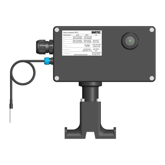
Page 13: Led-Status Indication
Operation and Installation Manual PBTC-200 LED-Status Indication The operating status of the thermostat module is indicated by the LED status display. This is indicated by color and flashing codes. Description of the color and blink codes: Status Continuous ON 1 flash impulse... -
Page 14: Technical Data
Operation and Installation Manual PBTC-200 Technical Data Dimensions 21-54C3-7D0001/- Notice: Technical data subject to change without notice. Page 12 / 45 04/2021-EHT-441168 No claims for damage arising from alternations, errors or misprints shall be allowed. -
Page 15: Operating Data
Operation and Installation Manual PBTC-200 Operating Data Parameter Values Nominal operating / control 80 - 277 VAC (50/60Hz) voltage 305 VAC Rated power without load 4,5 W Ambient temperature T -40°C to 55°C Storage temperature -50°C to 70°C Max. pipe temperature max. - Page 16 Order no. Heat output (W/m) max. ambient temperature +45°C max. ambient temperature +50°C max. ambient temperature +55°C see datasheet of heating cable type BARTEC HTSB 21-54C3-7D0001/- Notice: Technical data subject to change without notice. Page 14 / 45 04/2021-EHT-441168 No claims for damage arising from alternations, errors or misprints shall be allowed.
-
Page 17: Accessories
Operation and Installation Manual PBTC-200 Accessories Glass cloth tape Catalog No: GT-164 Order No.: 392328 For attaching self-regulating trace heaters on Part No.: 02-5500-0047 all pipes including stainless steel / required during preparation of power limiting trace heaters 12 mm x 50 m per roll Minimum installation temperature (dry surface): -10 °C... -
Page 18: Spare Parts
Operation and Installation Manual PBTC-200 for pipe ø up to 3” / DN80: Stainless steel pipe straps Catalog No: PC-1 Stainless steel, for attaching mounting Order No.: 435727 stands on pipes etc. No special tooling re- for pipe ø up to 3” / DN80: quired. -
Page 19: Functional Description
Operation and Installation Manual PBTC-200 Functional Description The thermostat module ETM-25Ex-C switches the connected heating load or heating cable on or off by means of a built-in relay. It switches on when the temperature measured at the Resistance Temperature Device Pt100 is lower than the temperature setpoint. It switches off if the measured temperature is higher than the set temperature plus hysteresis. -
Page 20: Transport
Operation and Installation Manual PBTC-200 Transport Sensitive components such as sensors are installed inside and outside the junction box with thermostat module. These must be protected from damage such as impact, moisture and dirt. Careful transport of the junction box with thermostat module must be ensured. -
Page 21: Installation And Assembly
Operation and Installation Manual PBTC-200 Installation and Assembly Required Tools / Equipment Safety Instructions WARNING The following tools and equipment are required for installa- tion of the PBTW-200-E: Wire cutters Utility knife Fire and electric shock hazard from electrical trace ... -
Page 22: Pre-Assembling The Mounting Stand
Operation and Installation Manual PBTC-200 Pre-assembling the Mounting Stand Slide a trace heater grommet onto the trace heater and into the seal seat. Feed the heating cable through the lower part of the mount- Slide the other trace heater grommet into the free seal ing stand. -
Page 23: Preparing The Heating Cable
Operation and Installation Manual PBTC-200 Slide the top unit of the mounting stand over the trace Push the grounding braid back. Use the screwdriver to form heater(s). an eyelet. Be careful not to damage the internal insulation Slightly tighten the 4 fixing screws using a crosshead jacket. - Page 24 Operation and Installation Manual PBTC-200 Remove 115 mm of the internal insulation jacket. Slide the green/yellow tube onto the twisted Take care not to damage the bus wires. grounding braid. Carefully make an incision into the edges of the heating element.
- Page 25 Operation and Installation Manual PBTC-200 Pull off the bus wires while holding the heating element. CAUTION Risk of malfunction of the heating system. Before you continue, make sure that the bus wires are intact and not nicked or damaged.
- Page 26 Operation and Installation Manual PBTC-200 Make sure that all bus wires are intact and not nicked or Thread the silicone pants onto the bus wires damaged. Thread the bus wires into the silicone pants. You might add further silicone adhesive to ensure optimal sealing.
-
Page 27: Installing The Mounting Stand
Operation and Installation Manual PBTC-200 Installing the Mounting Stand Now, tighten the 4 fixing screws of the top unit of the mounting stand using a 4 mm hex wrench Pull back the trace heaters. For easy cable connection it is enough when the silicone pants stands out of the mounting stand. - Page 28 Operation and Installation Manual PBTC-200 Install the pipe straps and tighten them firmly using a screwdriver. 21-54C3-7D0001/- Notice: Technical data subject to change without notice. Page 26 / 45 04/2021-EHT-441168 No claims for damage arising from alternations, errors or misprints shall be allowed.
-
Page 29: Connecting The Heating Cable And Power Supply
Operation and Installation Manual PBTC-200 Connecting the Heating Cable and Power Supply Screw the lock nut off the upper part of the mounting foot Insert heating cable into junction box Position junction box on the upper part of the mounting foot ... - Page 30 Operation and Installation Manual PBTC-200 Unscrew and remove the screw cap from the cable gland body of the cable bushing. Use adjustable spanner Slide the screw cap onto the power cable 21-54C3-7D0001/- Notice: Technical data subject to change without notice.
- Page 31 Operation and Installation Manual PBTC-200 Feed the mains cable through the cable gland body and junction box Tighten gland cap with 2 Nm tightening torque. Using a torque wrench/combination wrench 21-54C3-7D0001/- Notice: Technical data subject to change without notice.
- Page 32 Operation and Installation Manual PBTC-200 Connect the wires to the thermostat module according to the wiring diagram: Open the catch of the connection terminals with a slotted screwdriver 3.5 mm and connect the cable 21-54C3-7D0001/- Notice: Technical data subject to change without notice.
- Page 33 Operation and Installation Manual PBTC-200 Set temperature unit (°C or °F) on the changeover switch Set the temperature setpoint at the rotary coding switch (enter the 100, 10, 1 digit values, see the minimum/maximum value from the temperature control range in section 6.2 Operating Data ). Use a 2.5 mm slotted screwdriver ...
-
Page 34: Mounting The Resistance Temperature Device Pt100
Operation and Installation Manual PBTC-200 Mounting the Resistance Temperature Device Pt100 Cut in a triangle (5 mm) between the bus wires. Mount the Resistance Temperature Device directly on the pipe Mount the Resistance Temperature Device in the lower area of the pipe cross section ... -
Page 35: Applying The Pipe Insulation
Operation and Installation Manual PBTC-200 NOTICE Manufacturer recommendation: Measure insulation resistance before proceeding further Make sure that it is free of any faults, eliminate faults if necessary Procedure for insulation resistance measurement in Chapter 10 Commissioning Applying the Pipe Insulation ... -
Page 36: Commissioning
Operation and Installation Manual PBTC-200 Commissioning The thermostat module may only be commissioned by qualified personnel in accordance with their qualifications. Before carrying out further work on the system or on the junction box with thermostat module, it must be ensured that ... - Page 37 (0-2500 Vdc). Even if optimum conditions may not apply, all insulation resistance values should be greater than the IEC 60079-30.1:2015 minimum recommendation of 20 megohms. However, BARTEC strongly recommends a minimum reading of 1000 megohms. If the reading is lower or fluctuating, refer to section Troubleshooting on page 22.
- Page 38 The thermal insulation has been completely installed and is in a dry state. It is ensured that the heating circuit is operated within the data specified by BARTEC. NOTICE Complaints can only be accepted within the warranty period with a completely filled out acceptance report.
-
Page 39: Operation
During the operation of the electrical trace heating, it must be ensured that all components of the system are operated within the operating data specified by BARTEC. This applies in particular to the observance of maximum maintenance and ambient tempera- tures. -
Page 40: Maintenance
Operation and Installation Manual PBTC-200 Maintenance WARNING Risk of fire and electric shock from electrical trace heating system Risk of injury due to electric current When starting installation and maintenance work, disconnect all circuits from the power supply and check that they are... -
Page 41: Decommissioning
Operation and Installation Manual PBTC-200 Decommissioning WARNING Risk of fire and electric shock from electrical trace heating system Risk of injury due to electric current When starting installation and maintenance work, disconnect all circuits from the power supply and check that they are... -
Page 42: Recommissioning
Operation and Installation Manual PBTC-200 Recommissioning WARNING Risk of fire and electric shock from electrical trace heating system Risk of injury due to electric current When starting installation and maintenance work, disconnect all circuits from the power supply and check that they are... -
Page 43: Disposal And Recycling
Operation and Installation Manual PBTC-200 Disposal and Recycling The junction box with thermostat module must be disposed of properly in accordance with the legal regulations. It consists mainly of glass fiber reinforced plastic, metal and electrical components. The connection housing with thermostat module must be dismantled into its components and fed back into the recycling system according to its components. -
Page 44: Troubleshooting
Operation and Installation Manual PBTC-200 Troubleshooting Problem Possible cause Remedy Trace heater remains No power supply Check the power wiring for continuity to circuit breaker. cold Trace heater bus wires or power wir- Connect the trace heater and power wiring according to the in- ing not properly connected stallation instructions. -
Page 45: Acceptance And Test Report
Operation and Installation Manual PBTC-200 Acceptance and Test Report The acceptance test report is available on the company homepage www.bartec.com. 21-54C3-7D0001/- Notice: Technical data subject to change without notice. Page 43 / 45 04/2021-EHT-441168 No claims for damage arising from alternations, errors or misprints shall be allowed. -
Page 46: Limited Product Warranty
Limited Product Warranty Scope BARTEC warrants that all BARTEC products and accessories that are the subject of this manual will be free from defects in materials and workman-ship from and after its date of purchase for a period of 12 (twelve) months. -
Page 47: Eu Declaration Of Conformity
Operation and Installation Manual PBTC-200 EU Declaration of Conformity 21-54C3-7D0001/- Notice: Technical data subject to change without notice. Page 45 / 45 04/2021-EHT-441168 No claims for damage arising from alternations, errors or misprints shall be allowed. - Page 48 Fax: +44-8444 992 715 Int Fax: +44 161 767 1591 info@bartec.co.uk www.bartec.co.uk BARTEC NORWAY BARTEC SWEDEN (& DK, FI, LT, LV, EE) BARTEC RUSSIA BARTEC Technor AS BARTEC AB OOO „BARTEC Rus“ Vestre Svanholmen 24 Tennvägen 1 5A, bld. 1 Volkovskoe Shosse...
Need help?
Do you have a question about the PBTC-200 and is the answer not in the manual?
Questions and answers