Table of Contents
Advertisement
Quick Links
Advertisement
Table of Contents

Related Manuals for Bartec APEXmv 07-37A2-2211 730 Series


Summary of Contents for Bartec APEXmv 07-37A2-2211 730 Series
- Page 1 Operat ing Inst ruct ions Ex p Cont rol unit APEX...
- Page 2 Variant: Stainless steel enclosure APEX , Type 07-37A2-3211/*730 Variant: Polyester enclosure ATEX / IECEx Zone 1 / 21 Document number: 01-37A2-7D0005 Revision: 0 Order number: 452084 BARTEC GmbH Phone: +49 7931 597-0 Support: info@bartec.de Max-Eyth-Straße 16 Fax: +49 7931 597-480 Internet: www.bartec.de...
- Page 3 Page 2 of 80 01-37A2-7D0005_MV_Manual_Exp-Control-Unit_2021005_0_en.docx Rev. 0...
-
Page 4: Table Of Contents
Ex p Control unit Table of contents APEX 0 Table of contents Table of contents ....................3 About these operating instructions ................. 6 Highlighting in the document ..................6 Warnings ........................6 Symbols and icons ..................... 7 Technical changes ..................... 7 Languages ......................... - Page 5 Ex p Control unit Table of contents APEX Product description ....................18 General information ....................18 Ex p control unit APEX , type 07-37A2-2211/*730 ..........19 Structure of APEX control unit, type 07-37A2-2211/*730 ........19 Ex p control unit APEX , type 07-37A2-3211/*730 ..........
- Page 6 Ex p Control unit Table of contents APEX Error log ........................51 Temperature sensors ....................52 Extended ......................... 54 Menu „Network“ ...................... 57 Menu „Language“ ....................58 System status ......................58 Reading container data .................... 59 Ex p configuration ....................60 General ........................
-
Page 7: About These Operating Instructions
Should you require further information, please request the required information from your local or responsible BARTEC branch. Read the operating instructions and in particular the safety instructions carefully before using the device. -
Page 8: Symbols And Icons
The original user manual is written in German. All other available languages are translations of the original user manual. The user manual is available in German and English. If further languages are required, these must be requested from BARTEC or stated when placing the order. Rev. 0 01-37A2-7D0005_MV_Manual_Exp-Control-Unit_2021005_0_en.docx... -
Page 9: Safety
Ex p Control unit Safety APEX 2 Safety Intended use Exclusive purpose The Ex p control unit type 07-37A2-2211/*730 serves exclusively as a controlling and monitoring device for pressurised enclosures and is intended for use in explosion group II, category 2GD and temperature class T4 or for use in dusty environments with surface temperatures of T130 °C. -
Page 10: Warranty
Ex p Control unit Safety APEX Warranty WARNING UNAUTHORISED MODIFICATIONS AND/OR ALTERATIONS TO THE CONTROL SYSTEM. Explosion protection as well as design and manufacture in line with strain and safety requirements are no longer guaranteed. Before making any modifications or alterations, contact the manufacturer to obtain written approval. -
Page 11: Safety Instructions
Please observe the national waste disposal regulations for disposal. Servicing Regular servicing is not necessary if the device is operated correctly in accordance with the installation instructions and ambient conditions. BARTEC recommends annual servicing and inspection. See Chapter “Maintenance and care”. Page 10 of 80 01-37A2-7D0005_MV_Manual_Exp-Control-Unit_2021005_0_en.docx... -
Page 12: Avoidance Of Damage To Property
Ex p Control unit Safety APEX Repairs Repairs on explosion-protected equipment may be done only by authorised persons working in accordance with the latest development in technology and using original spare parts. The applicable provisions must be observed. Repairs must be carried out in accordance with EN / IEC 60079-19 / ГОСТ 31610.19-2014. -
Page 13: Aggressive Cleaning Agents
Ex p Control unit Safety APEX Aggressive cleaning agents When selecting the correct cleaning agent, it is essential that it is suitable for use since otherwise damage may occur to seals and connections. Combustible products are generally not permitted. Danger to health due to improper disposal According to the European WEEE Directive, electrical and electronic equipment may not be disposed of with household waste. -
Page 14: Marking And Test Certificate
Ex p Control unit Safety APEX Marking and test certificate The Ex p control unit is approved for the following areas. Ex p control unit APEX, type 07-37A2-2211/*730 ATEX (Europe) II 2(1)G Ex eb mb ib [ib pxb] [ia Ga] IIC T5/T4 Gb Marking II 2(1)D Ex tb [ib pxb] [ia Da] IIIC T130 °C / T95 °C Db Test certificate... -
Page 15: Standards Complied With
Ex p Control unit Safety APEX Standards complied with Ex p control unit APEX, type 07-37A2-2211/*730 Standard Designation Explosive atmospheres – Part 0: General EN IEC 60079-0:2018/AC:2020 requirements IEC 60079-0:2011 Edition: 6.0 ГОСТ 31610.0-2014 Explosive atmospheres - Part 2: Equipment EN 60079-2:2014 protection by pressurised enclosure “p”... -
Page 16: Ex P Control Unit Apex, Type 07-37A2-3211/*730
Ex p Control unit Safety APEX Ex p control unit APEX, type 07-37A2-3211/*730 Standard Designation Explosive atmospheres – Part 0: General EN IEC 60079-0:2018/AC:2020 requirements IEC 60079-0:2011 Edition: 6.0 ГОСТ 31610.0-2014 Explosive atmospheres - Part 2: Equipment EN 60079-2:2014 protection by pressurised enclosure “p” IEC 60079-2:2007 Edition: 5.0 ГОСТ... -
Page 17: Sil Qualification / Safety According To Iec 61508
Ex p Control unit Safety APEX SIL qualification / Safety according to IEC 61508 Important notes and information on the safe handling of the product. SIL qualification During the development of the Ex p control unit, special attention is paid to the avoidance of systematic errors and the detection and control of random errors. -
Page 18: Safety Parameters
Ex p Control unit Safety APEX Safety parameters THE FOLLOWING SAFETY PARAMETERS ARE WITHOUT OPTIONAL SENSORS. The optional sensors must be considered to determine the total failure rate! The safety parameters may be derived from the documentation on the optional sensors used. Safety parameters according to IEC/EN 61508 / DIN EN ISO 13849-: SIL = 2 Performance Level: = d... -
Page 19: Product Description
Ex p Control unit Product description APEX 3 Product description General information The Ex p type of protection, referred to as “pressurised enclosure”, is based on the measure of purging out any explosive gases that are in a closed enclosure and then generating and maintaining a level of pressure that is higher than that of the ambient atmosphere. -
Page 20: Ex P Control Unit Apex Mv , Type 07-37A2-2211/*730
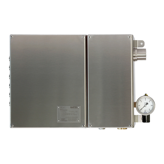
Ex p Control unit Product description APEX Ex p control unit APEX , type 07-37A2-2211/*730 The APEX control unit with its system components is an automatically operating control unit for monitoring, controlling and regulating pressurized enclosures in the hazardous areas of Zone 1 and Zone 21. The enclosure of type 07-37A2-2211/*730 is made of stainless steel V4A. -
Page 21: Ex P Control Unit Apex Mv , Type 07-37A2-3211/*730
Ex p Control unit Product description APEX Ex p control unit APEX , type 07-37A2-3211/*730 The APEX control unit with its system components is an automatically operating control unit for monitoring, controlling and regulating pressurized enclosures in the hazardous area of Zone 1. The enclosure of type 07-37A2- 3211/*730 is made of polyester. -
Page 22: Accessories
Ex p Control unit Product description APEX Accessories Valve fuse Valve fuse, type 05-0080-10** The valve fuse serves to secure the connected purging gas valve and is connected on the Ex e board of the control unit. p-operator panel p-Operator Panel, Type 17-51P5-*1111 The p-operator panel is a visualization unit for the control unit APEX. -
Page 23: Transport And Storage
4 Transport and storage Scope of delivery Missing parts or damage must be reported immediately in writing to the forwarding agent, the insurance company or BARTEC GmbH. Check the completeness of the scope of delivery using the delivery note. As standard, each Ex p control unit is delivered with the following scope of... -
Page 24: Storage
Ex p Control unit Transport and storage APEX Storage Store the control unit in a horizontal position and at a temperature of -25 °C to +60 °C in its original packaging. The environment must be dry, dust-free and low vibration. Store the control unit for a maximum of 2 years. -
Page 25: Installation
Ex p Control unit Installation APEX 5 Installation Before starting work, find out about the general safety instructions (see Chapter 2 Safety instructions). Deviations in the installation of customer-specific assemblies may occur. Observe the chapters Installation and Electrical connections. Carry out the installation according to the following sections, unless otherwise agreed for customer-specific control units. -
Page 26: Pressure Connections Apex
Ex p Control unit Installation APEX Pressure connections APEX Legend Electrical signal Pneumatic signal Pneumatic connection Rev. 0 01-37A2-7D0005_MV_Manual_Exp-Control-Unit_2021005_0_en.docx Page 25 of 80... -
Page 27: Typical Arrangement Ex P Control Unit Apex
Ex p Control unit Installation APEX Typical Arrangement Ex p Control Unit APEX Variant stainless steel: Variant polyester: The typical arrangement is remote mounting, e.g. wall mounting, with a maximum distance of 5 m and an inner diameter of at least 10 mm between Ex p control unit and protected equipment. -
Page 28: Electrical Connections
Ex p Control unit Electrical connections APEX 6 Electrical connections DANGER DEATH OR SERIOUS PHYSICAL INJURY DUE TO WORK ON LIVE PARTS. Fatal injury from electrical current. Observe the 5 safety rules for work on electrical systems: Disconnect mains; protect against unintended reconnection; verify the absence of voltage;... -
Page 29: General
Ex p Control unit Electrical connections APEX General Connection notes DANGER DEATH OR SERIOUS PHYSICAL INJURY WHEN THE COVER OF THE CONTROL UNIT APEX IS OPENED IN AN EXPLOSIVE ATMOSPHERE. Risk of explosion. Before opening the lid of the enclosure, check the atmosphere for any explosive gases. -
Page 30: Emc-Compliant Connection
EMC Directive. BARTEC Ex p control units can only operate safely and trouble free with an EMC- compliant wiring. This chapter supports you in the EMC-compliant design of your system. -
Page 31: Pre-Fuse
Ex p Control unit Electrical connections APEX 6.1.2.2 Earthing cables The earthing of a system satisfies protective and functional measures. Please observe the following points: Earthing cables should be as short as possible. Avoid ground loops. Use ground straps with a width of at least 10 mm. 6.1.2.3 Shielding In order to ensure trouble free operation of a system, cables with the largest possible surface area (not cross section) are important. -
Page 32: Inductive Loads
VDR resistor is exploited to become low-resistance above a certain threshold voltage. This short-circuits the self-induction voltage. Any oscillation that arises is damped by the RC snubber. Interference suppression measure, e.g. BARTEC 07-7311-93GU/K000 RC snubber Varistor 6.1.4.2 Protective circuit for DC supplied inductive loads This circuit variant is used for DC-powered relays / contactors. -
Page 33: Electrical Wiring Apex
Ex p Control unit Electrical connections APEX Electrical Wiring APEX Page 32 of 80 01-37A2-7D0005_MV_Manual_Exp-Control-Unit_2021005_0_en.docx Rev. 0... -
Page 34: Ex E" Connection Terminals
Ex p Control unit Electrical connections APEX “Ex e” connection terminals 6.2.1.1 Terminal row “X3” ATTENTION MATERIAL DAMAGE DUE TO INCORRECT SUPPLY VOLTAGE. Internal electronics of the Ex p control unit can be destroyed. Before activating the supply voltage, compare the value of the supply voltage with the printed value of the control unit. - Page 35 Ex p Control unit Electrical connections APEX 6.2.1.2 Terminal row “X5” The Ex p control unit has one floating changeover contact K3 and one floating changeover contact K4 for signaling and processing signals. The associated switching function can be set in the Ex p control unit via the WEB interface and is freely programmable.
- Page 36 Ex p Control unit Electrical connections APEX 6.2.1.4 Terminal row “X12” Floating signaling K2 can be classified as pure enable according to SIL when used. A floating signal (4x NO) is available on the Ex p control unit. This signal can either be used as an enable that is also safety related.
- Page 37 Ex p Control unit Electrical connections APEX 6.2.1.6 Terminal row “X6” ATTENTION MATERIAL DAMAGE DUE TO INCORRECT PRE-FUSING. Valve or control electronics may be damaged. Operate the digital outlet valve only with a 1.0 A pre-fuse and the proportional outlet valve only with a 1.6 A pre-fuse. The terminal row X6 is used to connect the outlet valve and the accompanying valve fuse.
-
Page 38: Connection Terminals "Ex I
Ex p Control unit Electrical connections APEX Connection terminals “Ex i” 6.2.2.1 Terminal row “X9” DANGER DEATH OR SERIOUS PHYSICAL INJURY DUE TO COMMISSIONING WITH BYPASS KEY SWITCH IN POTENTIALLY EXPLOSIVE ATMOSPHERE. Risk of explosion. Have the commissioning with a bypass key switch approved by the factory manager or his representative. - Page 39 Ex p Control unit Electrical connections APEX For the bypass switch to be detected and the function to be executed, a resistor with 620 Ω must be connected to the closing contact. The temperature sensor can be a PT 100 or 1000.
- Page 40 After changing or adapting parameters, a final function test must be performed. During normal operation of the Ex p system it may not be connected. The BARTEC parameter-setting switch must be used to change the parameters. The temperature sensor can be a PT 100 or 1000.
- Page 41 Ex p Control unit Electrical connections APEX 6.2.2.4 Terminal row “X13” ATTENTION ATTENTION WHEN CONNECTING EXTERNAL SENSORS TO THE EX P CONTROL UNIT. Ensure functional safety when connecting external sensors to the Ex p control unit! The external sensors must meet the requirements placed on SIL 2. Two functions can be executed at the optional current input as standard.
- Page 42 Ex p Control unit Electrical connections APEX 6.2.2.5 Terminal row “X15” ATTENTION ATTENTION WHEN CONNECTING EXTERNAL SENSORS TO THE EX P CONTROL UNIT. Ensure functional safety when connecting external sensors to the Ex p control unit! The external sensors must meet the requirements placed on SIL 2. Two functions can be executed at the optional current input as standard.
- Page 43 Ex p Control unit Electrical connections APEX 6.2.2.6 Terminal row “X17” The optionally available p operator panel can be connected to the terminal row “X17”. Terminal Connection Wire Function 3V3V_HMI Power supply Ground connection HMI_RX Data cable HMI_TX Data cable 6.2.2.7 Terminal row –...
-
Page 44: Operation
Ex p Control unit Operation APEX 7 Operation The individual menus of the Ex p control unit are described in the following chapters. Ex p specific configuration and settings are described in the Commissioning chapter. The complete solution is self-starting after connection of purging gas supply and supply voltage. - Page 45 Ex p Control unit Operation APEX Procedure: Open the network settings for the LAN interface on the PC/laptop. Select the properties of the LAN connection by pressing the “Properties” button. Open the network adapter settings using the “Configure…” button and select Advanced. Select the “Speed &...
-
Page 46: Operation Of The Web Interface
Ex p Control unit Operation APEX Operation of the WEB interface The web interface is operated using the input devices on the PC. Logging onto the WEB interface Two login levels are available on the WEB interface Level 1 Guest access User ID guest Password... -
Page 47: Input Of Parameters
Ex p Control unit Operation APEX Input of parameters Changing parameters in the Web interface must be carried out in a certain sequence: Procedure for changing parameters: Activate the parameter setting switch. Logging in to the web interface If you are already logged in, the web interface requires a new log-in. -
Page 48: Menu Structure Web-Interface
Ex p Control unit Operation APEX Menu structure WEB-Interface The WEB interface integrated in the Ex p control unit shows the following menu structure: Ex p Parameter Purge parameter Purge modi Pressure parameter Characterisitic Enclosure parameter Start page Info Status Messages File Parameter... -
Page 49: Web-Interface Operating Menu
Ex p Control unit Operation APEX WEB-Interface operating menu Purge parameter The "Ex p parameter / Purge parameter" menu contains the purge parameters. This includes the submenus Purge mode, Pressure parameter, Characteristics and enclosure parameters. 7.8.1.1 Purge mode The Ex p sequence control is defined in the "Purge mode" submenu. Manuel / Automatic = Determines whether the Ex p control unit performs purging with a fixed stored... - Page 50 Ex p Control unit Operation APEX 7.8.1.2 Pressure parameter The system pressures of the Ex p equipment are defined in the "Pressure parameter" submenu. po = Operating pressure. Pressure value at which control takes place during the operating phase. p1 = Minimum pressure. Shut-off value;...
-
Page 51: Start Page
Ex p Control unit Operation APEX 7.8.1.4 Enclosure parameter DANGER INCORRECT PARAMETERIZATION OF THE PROTECTED VOLUME IN THE EX P CONTROL UNIT. The purge process takes place with too low purge gas flow and there is a risk of residual explosive gases within the Ex p equipment. ... -
Page 52: Messages
Ex p Control unit Operation APEX Messages In the "Info / Messages" menu, the current system status is displayed as a plain text message. Green messages = Positive Yellow messages = Warning Red messages = Error messages Parameter Within the "Save / Parameters" menu, parameters from the Ex p control unit can be saved on a local computer or transferred from the local computer to... -
Page 53: Temperature Sensors
Ex p Control unit Operation APEX Temperature sensors Up to three temperature sensors in the PT100 or 1000 version can be connected to the Ex p control unit. In the menu "T. sensors" up to three PT100/1000 sensors can be configured. - Page 54 Ex p Control unit Operation APEX 7.8.7.1 Setting “Temperature sensors“ Procedure Connect the computer to the Ex p control unit / control station Activate the programming switch Log into the WEB interface at the user level Select the Extended / sensors menu ...
-
Page 55: Extended
Ex p Control unit Operation APEX Extended 7.8.8.1 Valves Im Menüpunkt „Ventile“ können das am Ex p Steuergerät angeschlossene Spülgasventil eingestellt werden. Der Auslieferungszustand ist in der Einstellung Digitalventil. Das jeweils aktivierte Spülgasventil ist mit folgendem Zeichen gekennzeichnet: Inlet valve Outlet valve Selection code Type... - Page 56 Ex p Control unit Operation APEX Procedure: Connect the computer to the Ex p control unit Activate the programming switch Log into the WEB interface at the user level Select the Extended / relay menu In the "of the respective relay" column, activate the specific message(s) by clicking on the related button.
- Page 57 Ex p Control unit Operation APEX Procedure: Connect the computer to the Ex p control unit Activate the programming switch Log into the WEB interface at the user level Select the “Extended / sensors” menu In the table shown you can activate the “Pressure sensor” function under Current sensor 1 or Current sensor 2.
-
Page 58: Menu „Network
Ex p Control unit Operation APEX 7.8.8.5 Menu „Display“ In the Display tab, the contrast and brightness of the LCD display can be set on the p-Operator Panel. 7.8.8.6 Menu „Password” A new password can be stored for the Guest and User in the Password tab. Menu „Network“... -
Page 59: Menu „Language
Ex p Control unit Operation APEX Menu „Language“ In the "Language" menu, the system language can be selected between German and English. System status By connecting the laptop to the Ex p control unit, initial information about the system keyboard can be called up on the start screen. Procedure for querying the system status ... -
Page 60: Reading Container Data
Ex p Control unit Operation APEX Reading container data Data is retrieved for the control room via a web browser or using an appropriate software tool to be provided by the customer that is able to send an HTML GET message equivalent to a browser request across the network to the APEX device. -
Page 61: Ex P Configuration
Ex p Control unit Ex p configuration APEX 8 Ex p configuration General The following sections describe the initial commissioning of the Ex p control unit. This means that it is described in detail how the Ex p control unit is set to the Ex p equipment created. -
Page 62: Ex P Settings - Manual Purge
Ex p Control unit Ex p configuration APEX Ex p settings – Manual purge After the applied purge gas valve is set, the Ex p specific parameters are set according to the following sections. Follow the individual chapters for the correct procedure to the parameters to be performed. - Page 63 Ex p Control unit Ex p configuration APEX 8.3.1.2 Setting the “Purge time” The procedure described here for determining the purging time is based on the principle of manual purging time calculation - All relevant parameters are assumed values - Ex p control with application proportional purge gas valve When using a proportional purge gas valve, the achieved purge pressure p3 is achieved by adjusting the internal pressure to the value 7/8 of p5.
- Page 64 Ex p Control unit Ex p configuration APEX 8.3.1.3 Setting the “Ex p parameters / pressure parameters“ The pressure parameters to be observed are part of IEC / EN 60079-2. Furthermore, the pressure parameters are application-dependent and must be checked during initial commissioning. The following values can be applied as a basic setting: po = 2.5 mbar (250 Pa) p1 = 1.0 mbar (100 Pa)
-
Page 65: Ex P Settings - Automatic Purge
Ex p Control unit Ex p configuration APEX Ex p settings – Automatic purge 8.3.2.1 Setting the “Purge program / Purge mode” DANGER DEATH OR SERIOUS BODILY INJURY FROM USE OF AN IMPROPER FLUSH MODE. Explosion risk. Only activate purge programs suitable for the application. ... - Page 66 Ex p Control unit Ex p configuration APEX 8.3.2.2 Setting the “Ex p parameters / pressure parameters“ The pressure parameters to be observed are part of IEC / EN 60079-2. Furthermore, the pressure parameters are application-dependent and must be checked during initial commissioning. The following values can be applied as a basic setting: po = 2.5 mbar (250 Pa) p1 = 1.0 mbar (100 Pa)
- Page 67 Ex p Control unit Ex p configuration APEX 8.3.2.3 Setting the “Ex p parameters / characteristics“ WARNING RISK OF DEATH OR INJURY CAUSED BY SETTING THE CHARACTERISTICS INCORRECTLY. The explosion protection is no longer guaranteed. Check the type number and corresponding characteristics of the pressure monitor.
-
Page 68: Functional Test And Procedure
Ex p Control unit Functional test and procedure APEX 9 Functional test and procedure Safety during operation DANGER DEATH OR SERIOUS INJURY CAUSED BY DAMAGED EXPLOSION PROTECTION MEASURE. Safe operation of the control unit is no longer possible. Risk of an explosion ... -
Page 69: Maintenance And Care
Ex p Control unit Maintenance and care APEX 10 Maintenance and care Find out about the general safety instructions before starting work (see Chapter 2.4 Safety instructions). Carry out maintenance and care in accordance with the following sections, unless otherwise agreed for customer-specific versions. Types of purging gas Only inert gas (e.g. -
Page 70: Visual Inspection
Furthermore, the function of the overall system should be checked. The correct sequence of the purging phase and of the operating phase should be checked. Repairs Repairs to the control unit and accessories may only be made by BARTEC GmbH. Faults and troubleshooting ATTENTION AN ALTERED OPERATING BEHAVIOUR CAN BE AN INDICATION OF ALREADY EXISTING DAMAGE TO THE CONTROL UNIT. -
Page 71: Faults
Ex p Control unit Maintenance and care APEX Faults Error / Fault Possible cause Remedy Sporadic failure Cable break Check connections Pressure drop / leakage Check tightness and leak compensation Control unit without Mains voltage not Check supply voltage function available Device defective Return to manufacturer... - Page 72 Ex p Control unit Maintenance and care APEX small nozzle after the pre- Wait until the increased purging phase flow rate has caused the internal temperature to drop or check the set temperature switching value Main switch or bridge to Switch on main switch or the terminals Hs_In / connect bridge to terminal...
-
Page 73: Error Messages
Ex p Control unit Maintenance and care APEX Error messages The control units give plain text messages which are divided into 3 categories. Positive messages are notifications that do not affect system availability. Warning messages are notifications that affect parts of the system. ... - Page 74 Ex p Control unit Maintenance and care APEX 10.4.2.3 Alarm messages Status Code Plain text 0000000D Ex p inactive The protected device is deactivated. 0000000E Device fault 1 HW test error (processors) 0000000F Device fault 2 HW test error (barriers) 00000010 Device fault 3 HW test error (internal temperature monitoring)
-
Page 75: Technical Data
Ex p Control unit Technical data APEX 11 Technical data Ex p control unit APEX, type 07-37A2-2211/*730 Parameters Specifications Type 07-37A2-2211/*730 EU type examination certificate BVS 19 ATEX E 015 X IECEx certification IECEx BVS 19.0038X ЕАЭС RU С-DE.АЖ58.В.01809/21 EAC certification II 2(1)G Ex eb mb ib [ib pxb] [ia Ga] IIC T5 / T4 Gb ATEX Marking II 2(1)D Ex tb [ib pxb] [ia Da] IIIC T95°C / T130 °C Db... -
Page 76: Ex P Control Unit Apex, Type 07-37A2-3211/*730
Ex p Control unit Technical data APEX Ex p control unit APEX, type 07-37A2-3211/*730 Parameters Specifications Type 07-37A2-3211/*730 EU type examination certificate BVS 19 ATEX E 015 X IECEx certification IECEx BVS 19.0038X ЕАЭС RU С-DE.АЖ58.В.01809/21 EAC certification ATEX Marking II 2(1)G Ex eb mb ib [ib pxb] [ia Ga] IIC T5 / T4 Gb IECEx Marking Ex eb mb ib [ib pxb] [ia Ga] IIC Gb... -
Page 77: Order Numbers
Ex p Control unit Order numbers APEX 12 Order numbers Ex p control unit APEX , standard Standard, stainless steel Ex p control unit APEXmv, DC wide voltage range 07-37A2-2211/1730 Ex p control unit APEXmv, AC wide voltage range 07-37A2-2211/2730 Standard, polyesterl Ex p control unit APEXmv, DC wide voltage range 07-37A2-3211/1730... -
Page 78: Annex
Ex p Control unit Annex APEX 13 Annex Purge air diagram 200 400 600 800 1000 1200 1400 1600 1800 2000 2200 2400 2600 2800 3000 3200 3400 3600 3800 4000 Durchfluss [l/h] Rev. 0 01-37A2-7D0005_MV_Manual_Exp-Control-Unit_2021005_0_en.docx Page 77 of 80... -
Page 79: Dimensions
Ex p Control unit Annex APEX Dimensions Ex p control unit APEX , 07-37A2-2211/*730 Page 78 of 80 01-37A2-7D0005_MV_Manual_Exp-Control-Unit_2021005_0_en.docx Rev. 0... -
Page 80: Ex P Control Unit Apex , 07-37A2-3211/*730
Ex p Control unit Annex APEX Ex p control unit APEX , 07-37A2-3211/*730 Software packages used The service area of hardware / software of the control unit APEX / SILAS uses the freeware freeRTOS Rev. 0 01-37A2-7D0005_MV_Manual_Exp-Control-Unit_2021005_0_en.docx Page 79 of 80... -
Page 81: Declaration Of Conformity
Ex p Control unit Declaration of conformity APEX 14 Declaration of conformity Ex p control unit APEX, Type 07-37A2-*2*1/**** Page 80 of 80 01-37A2-7D0005_MV_Manual_Exp-Control-Unit_2021005_0_en.docx Rev. 0... - Page 82 BARTEC BARTEC GmbH Max- Eyth- Str. 16 97980 Bad Mergentheim Germany Tel: + 49 7931 597 0 Fax: + 49 7931 597 119 Mail: info@bartec.com bart ec.com...
Need help?
Do you have a question about the APEXmv 07-37A2-2211 730 Series and is the answer not in the manual?
Questions and answers