
Subscribe to Our Youtube Channel
Related Manuals for Bartec SILAS A7-3741-1110/1000


Summary of Contents for Bartec SILAS A7-3741-1110/1000
- Page 1 Operating instructions SILAS Control Unit Control unit Type: A7-3741-1110/..Pressure monitor Type: 17-51P3-1604...
- Page 2 Operating instructions – SILAS control unit Ex pzc control unit for pressurized equipment Type: A7-3741-1110/*00* with pressure control module, type 17-51P3-1604 and accessories ATEX / IECEx Zone 2 / 22 Document: A1-3741-7D0001 Revision: G-04-2024 / 294266 A1-3741-7D0001 / REV-G-04-2024 / 294266 Subject to technical changes...
-
Page 4: Table Of Contents
Operating instructions – SILAS control unit Table of contents Table of contents Table of contents .......................... 3 General information ........................6 Manufacturer ..........................6 Purpose of these operating instructions ..................6 Languages ............................ 6 Technical changes ........................7 Additional documents ........................7 Conformity to standards and directives .................. - Page 5 Table of contents Operating instructions – SILAS control unit Mounting of the SILAS control unit – External mounting ..............16 Mounting of the SILAS control unit – Internal mounting ...............16 Mounting of the atmosphere measuring point ................17 4.4.1 Internal Mounting Kit, Type 05-0091-0275 ...................18 4.4.2 Internal Mounting Kit, Type 05-0091-0275 ...................18 Mounting the pressure monitor ....................19...
- Page 6 Operating instructions – SILAS control unit Table of contents 8.1.2 Preparation phase ........................34 8.1.3 Purging phase ..........................34 8.1.4 Operating phase ...........................35 Operating phases of the SILAS control unit [Dc] ................35 8.2.1 Flow diagram..........................35 8.2.2 Preparation phase ........................36 8.2.3 Operating phase ...........................36 Maintenance and care ........................37 Malfunctions and troubleshooting ....................39 10.1...
-
Page 7: General Information
These operating instructions are an integral part of the scope of delivery, even if they can be ordered and delivered separately for logistical reasons. - If you require any further information, please request it from your local or responsible BARTEC subsidiary. Please read the operating instructions and, in particular, the safety instructions carefully before using the device. -
Page 8: Technical Changes
General information Technical changes BARTEC reserves the right to change the contents of this document without prior notice. No guarantee is given for the correctness of the information. In case of doubt, the German safety instructions apply, as translation and printing errors cannot be ruled out. In the event of any legal dispute, the “General Terms and Conditions”... -
Page 9: Safety
Safety Operating instructions – SILAS control unit Safety Handling the product The product which is described in these operating instructions has left the factory in a safe and tested condition. In order to maintain this condition and to achieve faultless and safe operation of this product, it may only be used in the manner described by the manufacturer. -
Page 10: Operator's Obligations
Operating instructions – SILAS control unit Safety - Improper use of the SILAS control unit. - Improper installation, commissioning, operation and maintenance of the SILAS control unit. - Failure to observe the instructions in the manual regarding transport, storage, assembly, commissioning, operation and maintenance. -
Page 11: Safety Instructions For The Operation
Safety Operating instructions – SILAS control unit 2.5.2 Safety instructions for the operation When setting up or operating explosion-protected electrical systems, the IEC / EN 60079-14 regulations as well as the relevant installation and operating regulations must be observed. Maintenance - The relevant installation and operating regulations must be observed for electrical systems! (e.g. -
Page 12: Product Description
Operating instructions – SILAS control unit Product description Product description Type of protection “Ex p – pressurized enclosure” The type of protection Ex pD, known as “pressurized enclosure”, is based on the measure that explosive gases, which are present in a closed enclosure, are purged out and an overpressure is then generated and maintained relative to the surrounding atmosphere. -
Page 13: System Components Of The Silas Control Unit
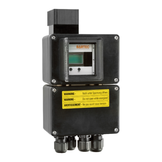
Product description Operating instructions – SILAS control unit System components of the SILAS control unit 3.3.1 SILAS control unit, type A7-3741-1110/*00* The SILAS control unit can be mounted inside or outside the pressurized enclosure. For internal mounting, e.g. on the mounting plate, the installation kit for internal mounting is also required. -
Page 14: Pressure Reducer With Pressure Gauge, Type 05-0056-008
Operating instructions – SILAS control unit Product description 3.3.4 Pressure reducer with pressure gauge, type 05-0056-008* This upstream pressure reducer is a diaphragm pressure regulator with secondary venting for reducing the pressure of externally supplied purging air. The setting is made by means of a hand wheel. The set reduced pressure can be read off via a pressure gauge. -
Page 15: Installation
Installation Operating instructions – SILAS control unit Installation Note Before starting any work, please read the general safety instructions (see Section 2 “Safety”). - Please observe the sections “Installation” and “Electrical Connections”. DANGER Unsuitable positioning of the Ex p control on the pressurized enclosure This results in unclean purging of the pressurized enclosure. -
Page 16: Internal Mounting - Gas Application
Operating instructions – SILAS control unit Installation 4.1.2 Internal mounting – Gas application Pos. Designation Ex pzc enclosure SILAS control unit Pressure monitor Purging gas nozzle Purging gas valve Pressure reducer Atmospheric measuring point 4.1.3 External mounting – Dust application Pos. -
Page 17: Mounting Of The Silas Control Unit - External Mounting
Installation Operating instructions – SILAS control unit Mounting of the SILAS control unit – External mounting ATTENTION Remove the fuse plugs after the installation has been completed! Incorrect measurement due to yellow protective cap at the measuring point - Remove the yellow protective cap at the pressure measurement before commissioning. -
Page 18: Mounting Of The Atmosphere Measuring Point
Operating instructions – SILAS control unit Installation Mounting of the atmosphere measuring point ATTENTION Faulty measurements due to contamination! A contaminated atmosphere measuring point leads to faulty measurements of the operating pressures. The faulty measurement deactivates the pressurized enclosure and therefore, it cannot be operated. - Check the atmosphere measuring point for any contamination at regular intervals. -
Page 19: Internal Mounting Kit, Type 05-0091-0275
Installation Operating instructions – SILAS control unit 4.4.1 Internal Mounting Kit, Type 05-0091-0275 - Drill a mounting hole with a diameter of 16.5 mm at the intended location on the pressurized equipment - Screw the venting screw (6) with sleeve (5) into the drilled hole. -
Page 20: Mounting The Pressure Monitor
Operating instructions – SILAS control unit Installation Mounting the pressure monitor CAUTION Incorrect installation or contamination of the pressure monitor! Incorrect installation or heavy contamination will prevent the excess pressure from escaping and lead to a sharp rise in pressure. - Check and ensure that the outlet screw connection is not covered from the outside. -
Page 21: Version G1/4", Gas
Installation Operating instructions – SILAS control unit Pressure Pressure Purging gas Supply Volume Pressure reducer monitor nozzle line < 50 litre 2 bar 1/4″ 2.8 mm 10 mm 50 to 300 litres 2 bar 1/4″ 3.9 mm 10 mm 300 to 700 litres 2 bar 1/2″... -
Page 22: Version G1/2", Gas
Operating instructions – SILAS control unit Installation Item Designation Remark Purging gas nozzle Included in the scope of delivery (2) Purging gas valve Included in the scope of delivery (6) Sealing washer Included in the scope of delivery (6) Reducing sleeve G 1/4”i / G3/8”a Detachable double nipple G1/4”... - Page 23 Installation Operating instructions – SILAS control unit Procedure - Drill a hole with a diameter of 21 mm at the intended mounting position of the pressurized enclosure (6). - Mount the pressure reducer G1/2” (7) on the pressurized enclosure (6) by using the reducing sleeve (4) and the sealing washers (5).
-
Page 24: Version G1/4", Dust
Operating instructions – SILAS control unit Installation 4.6.3 Version G1/4″, dust There is no purging phase in a pressurized enclosure for dust applications and therefore, only positive overpressure is applied. Thus, there is also no purging gas valve. For dust applications, there is no purging phase in a pressurized enclosure and thus, only positive overpressure is applied. -
Page 25: Electrical Connections
Electrical connections Operating instructions – SILAS control unit Electrical connections DANGER Death or serious physical injury from working on live parts! Danger to life due to electric current. - The 5 safety rules for working on electrical systems must be observed: Disconnect; secure against reconnection;... -
Page 26: Inserting And Fitting Of Connection Cables
The terminal board located in the connection enclosure of the SILAS Ex p control unit has two fuses F1 (purging valve) and F2 (main fuse). Fuse F1 is designed for the BARTEC standard purging valves. If any other flush valves are used, it must be ensured that the fuse corresponds to the required value of the purging valve. -
Page 27: Operation
Operation Operating instructions – SILAS control unit Operation Setting the parameters The parameters are set via the SILAS operating menu. For this purpose, the SILAS control unit is equipped with a rotary switch and 3 buttons. The individual functions of the rotary switch and the buttons are explained in the following sections. -
Page 28: Bypass Operation
Operating instructions – SILAS control unit Operation Procedure - Turn the “Parameter” switch (2) to the position for those parameters which have to be set. - Set each parameter to be set by using the “-” (4) or “+” (3) buttons. - Save each set value with the “SET”... -
Page 29: Commissioning
Commissioning Operating instructions – SILAS control unit Commissioning DANGER Risk of explosion if parameters are incorrect! Incorrect parameters and settings cancel the explosion protection. - Check the settings and parameters by using the “four eyes principle”. General settings for the commissioning process 7.1.1 Purging function Dependent on the application, various purging functions can be assigned to the SILAS control unit. -
Page 30: Adjusting The Leakage Air Needle Valve
Operating instructions – SILAS control unit Commissioning 7.1.3 Adjusting the leakage air needle valve The leakage air needle (1) is used to determine the internal pressure during the operation of the Ex p equipment. In order to enable that the SILAS Ex p control unit switches to the “Purging function”, it is important to adjust the leakage air needle correctly. -
Page 31: Commissioning The Silas Control Unit [Gc]
The initial commissioning of the SILAS control for the gas explosion hazardous area is shown in the following sections. In order to ensure that the SILAS control unit is parameterised and set safely, BARTEC recommends the following routine procedure: - Before commissioning, check the electrical equipment which is mounted inside the pressurized enclosure. -
Page 32: Determination Of The Purging Pressure P3
Operating instructions – SILAS control unit Commissioning 7.2.2 Determination of the purging pressure p3 In order to determine the purging pressure, close the pressurized enclosure and start up the SILAS control unit. Procedure - Set the “ON/OFF” rotary switch to position 1. - Set the “Parameter”... -
Page 33: Checking The Pre-Purge Phase
Commissioning Operating instructions – SILAS control unit Example 2: Cabinet volume = 720 l; Purging = 5-fold; 2 pressure monitors Adjusting the switching value “P3” = 12.0 mbar as described in Section 7.2.2 “Determination of the purging pressure” Flow rate according to the diagram = 24,000 l/h 720 litres x 60 = 9 minutes... -
Page 34: Commissioning The Silas Control Unit [Dc]
Operating instructions – SILAS control unit Commissioning Commissioning the SILAS control unit [Dc] 7.3.1 Determination of the operating pressure In order to ensure that the minimum internal pressure is maintained, the leakage air rate of the enclosure must be adjusted at the adjustable purging gas nozzle, since each pressurized enclosure has individual leakage losses. -
Page 35: Operation
Operation Operating instructions – SILAS control unit Operation Operating phases of the SILAS control unit [Gc] The operation of a pressurized enclosure built for the gas explosion hazardous area can be divided into three phases. The three phases are divided into the preparation, pre-purge and operating phase. -
Page 36: Operating Phase
Operating instructions – SILAS control unit Operation The purging process is constantly monitored by the sensors in the sensor module and the pressure switch. - Opening the purge gas valve increases the flow with purging gas. - The disc, which is integrated in the pressure switch, is lifted. - The switching values of minimum pressure “P1”... -
Page 37: Preparation Phase
Operation Operating instructions – SILAS control unit 8.2.2 Preparation phase During the preparation phase, all internal dust deposits must be removed before the pressurized enclosure is activated. After cleaning the pressurized enclosure, the door is closed, the SILAS control unit is put into operation and the purging gas supply is activated. The activation of the purging gas supply causes purging gas to flow into the pressurized enclosure via the adjustable leakage air needle, resulting in an overpressure relative to the surrounding atmosphere. -
Page 38: Maintenance And Care
Operating instructions – SILAS control unit Maintenance and care Maintenance and care WARNING Maintenance intervals If it is used correctly and in accordance with the installation instructions and ambient conditions, the maintenance interval must be observed pursuant to EN 60079-17. - Maintenance interval max. - Page 39 Maintenance and care Operating instructions – SILAS control unit Pos. Inspection point Commissioning Maintenance Testing of the wiring in accordance with the relevant guidelines If applicable, checking whether there are viewing panels made of laminated safety glass or plastic (with a sign “avoid electrostatic charge, wipe with a damp cloth”) General condition of the attachments of the pressurized enclosure (support feet, rain canopy...
-
Page 40: Malfunctions And Troubleshooting
Operating instructions – SILAS control unit Malfunctions and troubleshooting Malfunctions and troubleshooting It is assumed that the connection of all external electrical and mechanical devices has been carried out properly. Therefore, the proper setup and connection of the electrical devices should be checked first. - Page 41 Malfunctions and troubleshooting Operating instructions – SILAS control unit Fault Possible cause Remedy The digital purging gas Purging gas is fed into the pressurized Reduce the diameter of valve switches off enclosure in too large quantity. purging gas nozzle. briefly during the purging process.
-
Page 42: Technical Data
Operating instructions – SILAS control unit Technical data Technical data 11.1 Ex pz SILAS control unit 11.1.1 Explosion protection Type A7-3741-1110/.00. Certifications ATEX, IECEx, EAC, KCs, INMETRO, US/CA (NEC505), UKCA Area of use Zone 2, Zone 22 ATEX / UKCA Certification TÜV 09 ATEX 553359 X / CML 21UKEX1862X Marking... -
Page 43: Electrical Data
Technical data Operating instructions – SILAS control unit Type A7-3741-1110/.00. NEC 505/CEC505, US/CA Certification CSA 13.2654547 Marking (US) Class I, Zone 2: AEx nA nC [pz] IIC T4/T6 Gc Marking (CA) Class I, Zone 2: Ex nA nC [pz] IIC T4/T6 Gc Marking (US) Class I, Zone 22: AEx tc [p] IIC T85 °C Dc Marking (CA) -
Page 44: Environmental Conditions
Operating instructions – SILAS control unit Technical data 11.1.5 Environmental conditions Type A7-3741-1110/.00. Transport and -20 °C to +60 °C storage temperature Operating temperature @ T4 -20 °C to +60 °C Operating temperature @ T6 -20 °C to + 40 °C Relative humidity <... -
Page 45: Ordering Information
Ordering information Operating instructions – SILAS control unit Ordering information 12.1 SILAS control unit Designation Order number SILAS control unit, AC 230 V A7-3741-1110/1000 SILAS control unit, AC 115 V A7-3741-1110/2000 SILAS control unit, DC 24 V A7-3741-1110/4000 SILAS control unit with window, AC 230 V A7-3741-1110/1002 SILAS control unit with window, AC 115 V A7-3741-1110/2002... -
Page 46: Appendix
Operating instructions – SILAS control unit Appendix Appendix 13.1 Dimensions of the Ex pz SILAS control unit 13.1.1 Block diagram A1-3741-7D0001 / REV-G-04-2024 / 294266 45 / 48 Subject to technical changes... -
Page 47: Dimensions Of The Pressure Monitor
Appendix Operating instructions – SILAS control unit 13.2 Dimensions of the pressure monitor 13.2.1 Drilling pattern 13.3 Dimensions of the pressure monitor Subject to technical changes 46 / 48 A1-3741-7D0001 / Rev-G-04-2024 / ESS-294266... -
Page 48: Purging Gas Diagram
Operating instructions – SILAS control unit Appendix 13.4 Purging gas diagram 1x 17-51P3-1604 2x 17-51P3-1604 Q [m³/h] A1-3741-7D0001 / REV-G-04-2024 / 294266 47 / 48 Subject to technical changes... -
Page 49: Declaration Of Conformity
Declaration of Conformity Operating instructions – SILAS control unit Declaration of Conformity Subject to technical changes 48 / 48 A1-3741-7D0001 / Rev-G-04-2024 / ESS-294266... - Page 50 BARTEC BARTEC GmbH Max-Eyth-Str. 16 97980 Bad Mergentheim Germany Tel: +49 7931 597 0 Fax: +49 7931 597 480 Mail: info@bartec.com bartec.com...
Need help?
Do you have a question about the SILAS A7-3741-1110/1000 and is the answer not in the manual?
Questions and answers