Sign In
Upload
Manuals
Brands
Bartec Manuals
Control Unit
SILASPZ
Bartec SILASPZ Control Unit Manuals
Manuals and User Guides for Bartec SILASPZ Control Unit. We have
2
Bartec SILASPZ Control Unit manuals available for free PDF download: Manual, Operating Instructions Manual
Bartec SILASPZ Manual (90 pages)
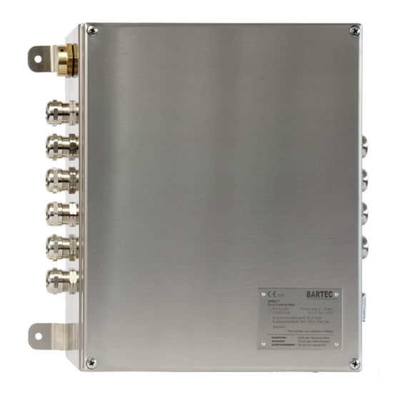
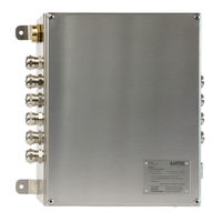
Ex p Control Unit
Brand:
Bartec
| Category:
Control Unit
| Size: 5 MB
Table of Contents
Table of Contents
4
About These Operating Instructions
8
Highlighting in the Document
9
Warnings
9
Symbols and Icons
10
Technical Changes
10
Languages
10
Safety
11
Intended Use
11
Exclusive Purpose
11
Improper Use
11
Warranty
11
Safety Instructions
12
General
12
Safety Instructions for Operation
12
Avoidance of Damage to Property
13
Short Circuit Due to Improper Connection
13
Triggering the Safety Function
13
EMC-Compliant Connection
13
Storage at an Excessively High Temperature
13
Aggressive Cleaning Agents
14
Danger to Health Due to Improper Disposal
14
Obligations of the Owner
14
Instructions for Use
14
Marking and Test Certificate
15
Ex P Control Unit SILAS, Type A7-37S2-2111/*520
15
Standards Complied with
15
Product Description
17
General Information
17
Ex P Control Units SILAS
17
SILAS Design, Type A7-37S2-2111/*520
18
Accessories
19
Valve Fuse
19
Pressure Outlet
19
Purge Gas Valve
19
P-Operator Panel
19
Programming Switch
20
Programming Cable
20
Transport and Storage
21
Scope of Delivery
21
Packaging
21
Transport
21
Storage
22
Disposal
22
Installation
23
Installation Ex P Control Unit, Type A7-37S2-2111/*520
23
Installation of the Pressure Outlet
23
Assembly "Internal Mounting Kit, Type 05-0091-0275
24
Assembly "External Mounting Kit, Type 05-0091-0280
25
Installation Purging Gas Supply
26
Version G1/4
27
Version G1/2
28
Version G1/4" (Dust Application)
29
Pneumatic Connections
30
Pneumatic Connections SILAS, Type A7-37S2-2111/*520
30
Typical Installations
30
Typical Arrangement - Outside Installation / Gas Application
31
Typical Arrangement - Inside Installation / Gas Application
32
Typical Arrangement - Outside Installation / Dust Application
33
Typical Arrangement - Inside Installation / Dust Application
34
Electrical Connections
35
General
36
Connection Notes
36
EMC-Compliant Connection
37
Pre-Fuse
38
Inductive Loads
39
Electrical Wiring SILAS
40
Ex E" Connection Terminals
41
Connection Terminals "Ex I
45
Operation
49
WEB Interface
49
Adjusting the LAN Connection
49
Operation of the WEB Interface
51
Logging Onto the WEB Interface
51
Navigation in the WEB Interface
51
Input of Parameters
52
LED Indicators
52
Menu Structure WEB-Interface
53
WEB-Interface Operating Menu
54
Purge Parameter
54
Start Page
57
Status
57
Messages
57
Parameter
58
Temperature Sensors
58
Extended
60
Menu „Network
63
Menu „Language
63
System Status
64
Reading Container Data
65
Commissioning
66
General
66
Sequence for the Settings
66
Parameterization of Purge Gas Valve
66
Setting for "Leakage Air Compensation" Digital Valves
67
Configuration for Gas Applications
67
Ex P Settings - Manual Purge
67
Ex P Settings - Automatic Purge
71
Configuration for Dust Applications
74
Ex P Settings
74
Functional Test and Procedure
76
Safety During Operation
76
Functional Flow Diagram for the Ex P Control Station
76
Ex P Control Flow Chart
76
Functional Flow Diagram - Dust
77
Maintenance and Care
78
Types of Purging Gas
78
Maintenance Work
78
Maintenance Intervals
78
Visual Inspection
79
Cleaning
79
Regular Maintenance
79
Repairs
79
Faults and Troubleshooting
79
Faults
80
Error Messages
82
Technical Data
84
Order Numbers
85
Ex P Control Unit SILAS, Standard
85
Pressure Outlet Module
85
Valve Fuse
85
Purge Gas Valve
85
Operator Panel
85
Installation Accessories
85
Protective Circuits
85
Annex
86
Purge Diagram
86
Sequence Diagram
87
Dimensions
88
Ex P Control Unit SILAS, Type A7-37S2-2111/*520
88
Pressure Outlet, Type 17-51P3-1603
88
Software Packages Used
88
Declaration of Conformity
89
Ex P Control Unit SILAS, Type A7-37S2-*1*1
89
Advertisement
Bartec SILASPZ Operating Instructions Manual (82 pages)
Ex p control unit
Brand:
Bartec
| Category:
Control Unit
| Size: 4 MB
Table of Contents
Table of Contents
4
General Information
8
Manufacturer
8
Purpose of These Operating Instructions
8
Languages
8
Technical Changes
9
Additional Documents
9
Conformity to Standards and Directives
9
Explanation of the Individual Markings
9
Markings in the Operating Instructions
9
Markings on the Device
9
Safety
10
Handling the Product
10
Intended Use
10
Exclusive Intended Use
10
Non-Intended Use
10
Warranty
10
Operator's Obligations
11
Safety Instructions
11
General Safety Instructions
11
Safety Instructions for the Operation
12
Product Description
13
Type of Protection "Ex P - Pressurized Enclosure
13
SILAS Pz Control Unit, Type A7-37S2-2111/*520
13
Design Type SILAS Pz A7-37S2-2111/*520
14
System Components of the Ex P Control Unit SILAS
14
Purge Gas Valve, Type 05-0056-00
14
Pressure Monitor, Type 17-51P3-1604
14
Pressure Reducer with Pressure Gauge, Type 05-0056-008
15
Valve Fuse, Type 05-0080-10
15
P-Operator Panel, Type 17-51P5-*111
15
Programming Enable/Switch, Type 05-0003-0089
16
Interface Cable, Type 03-9828-0062
16
Transport and Storage
17
Scope of Delivery
17
Packaging
17
Transport
17
Storage
17
Disposal
17
Installation
18
System Design
19
General
19
Mounting the Ex P Control Unit SILAS
19
Mounting the SILAS Control Unit - External Installation
20
External Installation Kit, Type 05-0091-0280
20
Mounting the SILAS Control Unit - Internal Installation
20
Internal Installation Kit, Type 05-0091-0275
21
Mounting the Pressure Monitor
21
Purge Gas Supply
22
Version G1/4", Gas
23
Version G1/2", Gas
24
Version G1/4", Dust
25
Electrical Connections
26
Wiring Instructions
26
Inserting and Laying Connecting Cables
27
EMC-Compliant Connection
27
Back-Up Fuse
28
Inductive Loads
29
Electrical Wiring
30
Terminal Block Overview
30
Wiring Diagram
31
Ex E Connection Terminals
31
Ex I Connection Terminals
34
Operation
38
Configuration of the LAN Interface
38
Setting the LAN Connection
38
Operating the WEB Operating System
40
Logging into the WEB Operating System
40
Navigating in the WEB Operating System
40
Entering Parameters
40
Menu Structure of the WEB Operating System
41
BARTEC Operating Instructions - Ex P Control Unit SILAS
42
LED Displays on the Ex P Functional Unit
42
WEB Operating System Operating Menu
42
Ex P Parameters / Purge Parameters
42
Info
45
Saving
46
Settings / Advanced
46
System Status
51
Reading out Data Containers
51
Commissioning
53
General
53
Sequence for the Initial Commissioning
53
Parameterisation of the Purge Gas Valve
53
Setting the Digital Purge Gas Valve "Leakage Air Compensation
54
Commissioning the SILAS Pz Control Unit [Gc]
54
Procedure Ex P Settings - Manual Purge
54
Procedure Ex P Settings - Automatic Purge
58
Function Test Ex P
61
Commissioning the SILAS [DC] Control Unit
62
Procedure Ex P Settings
62
Follow the same Procedure for the Other Pressure Parameters Function Test Ex P
64
Operation
65
Safety During the Operation
65
Operating Phases of the Ex P Control Unit SILAS
65
Flow Chart
65
Preparation Phase
65
Purge Phase
66
Operating Phase
66
Operating Phases of the SILAS [DC] Control Unit
67
Flow Chart
67
Preparation Phase
67
Operating Phase
67
Maintenance and Care
68
Maintenance Work
68
Maintenance Intervals
68
Visual Inspection
68
Cleaning
69
Regular Maintenance
69
Malfunction and Troubleshooting
70
Fault Table
70
Error Messages
71
Technical Data
74
Ex Pz Control Unit SILAS
74
Explosion Protection
74
Electrical Data
74
Ex P Specific Data
75
Mechanical Data
75
Ambient Conditions
75
Pressure Monitor
76
Purge Gas Valve
76
Digital Purge Gas Valve
76
Proportional Purge Gas Valve
76
Purge Gas
76
Ordering Information
77
Ex Pz Control Unit SILAS
77
Pressure Monitor
77
Purge Gas Valve
77
Purge Gas Valve Safety Device
77
Purge Gas Nozzle Zone 22
77
Pressure Reducer
77
Installation Set
77
Appendix
78
Dimensions of the Ex Pz Control Unit SILAS
78
Block Diagram
78
Dimensions of the Pressure Monitor
79
Purge Gas Diagram
79
Software Packages Used
80
Declaration of Conformity
81
Advertisement
Related Products
Bartec SILASmpc
Bartec SFLJ
Bartec SFLP
Bartec SFLA
Bartec SFDN 150 ST
Bartec SFON 150 MT
Bartec SEDN 290 MT
Bartec SFON 125 QT
Bartec SFDN 250 OT
Bartec SFDEL Series
Bartec Categories
Measuring Instruments
Control Unit
Enclosure
Handhelds
Tablet
More Bartec Manuals
Login
Sign In
OR
Sign in with Facebook
Sign in with Google
Upload manual
Upload from disk
Upload from URL