Table of Contents
Advertisement
Quick Links
Advertisement
Table of Contents

Related Manuals for UGCS SkyHub


Summary of Contents for UGCS SkyHub
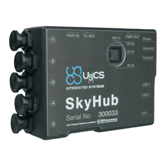
- Page 1 UgCS SkyHub User Manual integrated.ugcs.com February 2022 Revision 6...
- Page 2 • Added the Lightware SF30/D altimeter description • Changed the Description section • Removed the Attollo WASP-200 altimeter description • Removed the Lightware SF11/C altimeter description • Removed the UgCS SkyHub Device section • Removed the Kits section 13.01.2022 • Added the DJI M300 RTK description •...
- Page 3 Revision Date Description 05.11.2020 • Added the True Terrain Following v2.0 settings • Added the resuming and pausing TTF from UgCS-CPM description • Added the Geonics EM-61 metal detector description • Added the IGNORE_ERRORS to common altimeter settings • Added the SEG-Y Postprocessing Tool description •...
-
Page 4: Table Of Contents
........37 Setup the UgCS SkyHub Device . - Page 5 UgCS SkyHub User Manual Log Files Management ........75 Update Firmware .
-
Page 6: Description
(non-geotagged) is in most cases useless. UgCS SkyHub uses the positioning information from the drone to geotag sensor data. • UgCS SkyHub can supply NMEA coordinate stream to the external sensor. Some sensors have internal data recorders but require an external GPS receiver. UgCS SkyHub can act as such an additional GPS receiver by providing the UAV coordinates to sensors. -
Page 7: Interaction Diagrams With Drones
Interaction diagrams with drones UgCS SkyHub User Manual Interaction diagrams with drones UgCS SKYHUB API Port UART Onboard Software DJI Flight DJI Onboard (UgCS SkyHub) Controller DJI GNSS Payload Drone System Receiver Data Position DJI Air Ethernet UART Downlink UART / RS232... -
Page 8: Supported Sensors
Supported sensors UgCS SkyHub User Manual Supported sensors Power Data Data / feed Manufact Sensor logging control from Notes urer name on UgCS interface UgCS Skyhub Skyhub Altimeter (used for flight control in True Terraion-Following (TTF) and Grasshopper (GH) flight... - Page 9 Supported sensors UgCS SkyHub User Manual Power Data Data / feed Manufact Sensor logging control from Notes urer name on UgCS interface UgCS Skyhub Skyhub Magnetometer GPR feed MagDrone R3 (GPS-out) SENSYS / R4 from UgCS Skyhub Tested for MagArrow /...
- Page 10 Supported sensors UgCS SkyHub User Manual Power Data Data / feed Manufact Sensor logging control from Notes urer name on UgCS interface UgCS Skyhub Skyhub Other sensors and devices FT742-SM UART Technologies anemometer MR72 Nanoradar obstacles UART detector Emlid Reach M2...
-
Page 11: Assembling
• DJI M210 / M210 V2 • DJI M300 RTK The following steps are described for UgCS SkyHub 2 but may be applied to UgCS SkyHub 3 with a minor difference. DJI M600 / M600 Pro UgCS SkyHub Device 1. Put the M600 brackets to UgCS SkyHub. - Page 12 UgCS SkyHub User Manual Figure 2.2 — The UgCS SkyHub mounted onto the M600 drone 3. Connect the UgCS SkyHub to the drone’s power outlet (DC-18V) using included power cable. Attention! Do not connect any payload to this connector unless you are sure about the payload’s power voltage range.
-
Page 13: Dji M210 / M210 V2
1. Unscrew the original cable cover using a 1.5 hex driver. The screws will be used to fix the customized cable cover in place. Figure 2.5 — M210 API and Power connectors 2. Snap the UgCS SkyHub on the right leg of the drone. Copyright © 2019—2022, SPH Engineering Revision 6 • February 2022... - Page 14 Figure 2.6 — UgCS SkyHub on the M210 leg 3. Open the leg brace, slide the UgCS SkyHub up and close the leg brace. Check that the retaining tab is fixed by the leg brace and the brace is closed completely.
- Page 15 DJI M210 / M210 V2 UgCS SkyHub User Manual Figure 2.8 — Wire assembly 5. Put the 3-pin rectangular connector through the hole in the cable cover. Pushing it in as far as it goes will make it easier to plug the connector into the drone.
- Page 16 DJI M210 / M210 V2 UgCS SkyHub User Manual Figure 2.10 — 3-pin rectangular connector plugged into the drone 7. Push the cable cover over the connector making sure that the connector is fully seated. Figure 2.11 — M210 cable cover to be pushed 8.
- Page 17 UgCS SkyHub User Manual Figure 2.12 — M210 cable cover installed 9. Make the connections to the UgCS SkyHub. Attention! The data connectors have a different number of pins. Be sure to use the appropriate connectors and to line up the red dots.
- Page 18 Figure 2.14 — Power cable connected to the M210 11. The installation is complete. The end result is shown on the Figure 2.15 Figure 2.15 — The UgCS SkyHub mounted onto the M210 drone Copyright © 2019—2022, SPH Engineering Revision 6 • February 2022...
-
Page 19: Dji M300 Rtk
UgCS SkyHub User Manual DJI M300 RTK UgCS SkyHub Device 1. DJI M300 RTK TTF kit include UgCS SkyHub with mounting brackets, data and power cable and radio altimeter. Figure 2.16 — DJI M300 RTK UgCS SkyHub TTF kit 2. Snap the UgCS SkyHub on the right leg of the drone. - Page 20 DJI M300 RTK UgCS SkyHub User Manual 3. Connect UgCS SkyHub data and power cable to the drone OSD port. OSD port is placed under rubber cover from the top right drone side. Fix the cable bracket on the top of on M300 with M3 screw. Connect XT30 connector to UgCS SkyHub power in port and 3pin Lemo connector to 3 pin UgCS SkyHub port.
- Page 21 DJI M300 RTK UgCS SkyHub User Manual 5. The installation is complete. The end result is shown on the Figure 2.20 Figure 2.20 — The UgCS SkyHub mounted onto the M300 drone Copyright © 2019—2022, SPH Engineering Revision 6 • February 2022...
-
Page 22: Preparation
Important: It is strongly recommended to switch off a remote controller before any operations with the UgCS SkyHub Wi-Fi. After powering on the UgCS SkyHub operates as Wi-Fi access point with following credentials: • SSID: UgCS-SkyHub-****** (where ****** is the UgCS SkyHub serial number) •... - Page 23 UgCS SkyHub runs DHCP service onboard, therefore, the PC’s IP address will be assigned automatically after connection. Access to Onboard File System One may use any SCP client to access the UgCS SkyHub file system. For example, one may use WinSCP. Figure 3.1 — WinSCP settings While pressing the Login button one may choose between login via SCP (to have access to the file system) or opening with PuTTY (for SSH access).
-
Page 24: Setup Interface To Dji Autopilot
Setup Interface to DJI Autopilot To allow the UgCS SkyHub to connect to the DJI autopilot, one should activate and setup the Onboard SDK for its device, and setup the UgCS for DJI mobile application. DJI User’s Credentials Registration One needs to create and use own credentials for the DJI flight controller activating. - Page 25 5. Return to the DJI Developer area and open app details. Remember APP ID and App Key values. Figure 3.4 — Getting App ID and Key from App Information 6. Write these values to corresponding configuration fields in skyhub.conf (APP_ID and APP_KEY accordingly in [DJI] or [DJI_M] section) as described in Setup the UgCS SkyHub Device.
- Page 26 Setup Interface to DJI Autopilot UgCS SkyHub User Manual DJI Flight Controller Activation The following steps are described for the DJI A3 flight controller but may be applied to another DJI product with a minor difference. 1. Run the DJI Assistant 2 and check settings that at least DJI account information and Onboard SDK APP ID options are enabled.
- Page 27 Setup Interface to DJI Autopilot UgCS SkyHub User Manual Figure 3.6 — DJI Assistant 2 start window 3. Enter User’s DJI credentials created during DJI User’s Credentials Registration press Sign in button. Figure 3.7 — DJI Assistant 2 login window Copyright © 2019—2022, SPH Engineering...
- Page 28 Setup Interface to DJI Autopilot UgCS SkyHub User Manual 4. Switch on the drone, wait for the device to appear, open the main window, then choose the SDK/Onboard SDK tab and check Enable API Control and Ground Station Status checkboxes. Enable SDK Failsafe Actions should be also checked if Obstacle Avoidance sensors are used.
- Page 29 Setup Interface to DJI Autopilot UgCS SkyHub User Manual Figure 3.9 — Enable API control in DJI Assistant 2 6. Switch on the DJI Remote Controller, run DJI GO (DJI Pilot), choose the Me tab, press the Login button. 7. Enter User’s DJI credentials created during DJI User’s Credentials Registration...
- Page 30 Communication Ports in the DJI Pilot application for the first time. Figure 3.12 — DJI Pilot screen. Additional setups for DJI M210 11. Restart the drone by a power cycle. The UgCS SkyHub device should be properly connected to the flight controller.
- Page 31 Setup Interface to DJI Autopilot UgCS SkyHub User Manual DJI Obstacle Sensors Disabling Depending on the used payload, downwards obstacle sensors may need to be disabled (actual for DJI M300 RTK and DJI M210). Should use DJI Pilot to disable them according to the screenshots below.
- Page 32 UgCS SkyHub User Manual Setup the UgCS for DJI Mobile Application One should enable custom payload support in the UgCS for DJI mobile application. After starting the application go to Menu > Drone Specific Settings and enable the corresponding checkbox.
-
Page 33: Setup Interface To Ardupilot
UgCS SkyHub can be connected to the flight controller flashed with the ArduPilot 4.x.x firmware. 1. Make sure UgCS version 4.3 or higher is used (download links can be found in Prerequisites section) and VSM for ArduPilot vehicles is installed. - Page 34 6. Open application Mission Planner, connect it to the vehicle autopilot and check serial port settings used for UgCS SkyHub communication. Check port configured baud rate. Speed should be the same as configured at UgCS SkyHub side in the [MAV] section of the UgCS SkyHub config (recommended 230400). If adjustment is needed don’t forget write them and restart autopilot.
- Page 35 UgCS SkyHub and autopilot. Figure 3.19 — Mission Planner MAVlink inspector data Vehicle 2 and Comp 5 correspond to configured at UgCS SkyHub System (2) and Component (5) ID. 9. In case of correct Autopilot, UgCS and UgCS SkyHub configuration, Payload data b64 is displayed at drone telemetry in UgCS.
- Page 36 Setup Interface to ArduPilot UgCS SkyHub User Manual Figure 3.20 — UgCS, drone telemetry Copyright © 2019—2022, SPH Engineering Revision 6 • February 2022...
-
Page 37: Setup Interface To Px4
UgCS SkyHub User Manual Setup Interface to PX4 UgCS SkyHub can be connected to the flight controller flashed with the PX4 1.10.x or higher firmware. 1. Make sure UgCS version 4.3 or higher is used (download links can be found in Prerequisites section) and VSM for PX4 vehicles is installed. - Page 38 6. If UgCS SkyHub is connected to telemetry port 2, open application QGroundControl, then go to Parameters -> MAVLink and set parameter MAV_1_CONFIG to TELEM2. Copyright © 2019—2022, SPH Engineering...
- Page 39 Figure 3.24 — UgCS SkyHub PX4 TELEM2 port data forwarding configuration 9. Change baudrate for the TELEM2 Serial Port (recommended 230400). Speed should be the same as configured at UgCS SkyHub side in the [MAV] section of the UgCS SkyHub config.
- Page 40 Setup Interface to PX4 UgCS SkyHub User Manual Note: UgCS SkyHub subscribes to the following MAVLink messages with telemetry rate defined by the TELEMETRY_RATE parameter in the MAV section in UgCS SkyHub config file: GPS2_RAW GPS_RAW_INT GLOBAL_POSITION_INT ATTITUDE SYSTEM_TIME HEARTBEAT DISTANCE_SENSOR Copyright ©...
-
Page 41: Setup The Ugcs Skyhub Device
UgCS SkyHub User Manual Setup the UgCS SkyHub Device In order to configure the UgCS SkyHub software one should edit skyhub.conf file located in /etc/skyhub/ directory. This configuration file has a widely used INI like file format. The default configuration file created automatically if the configuration file doesn’t exist. - Page 42 Setup the UgCS SkyHub Device UgCS SkyHub User Manual ECHOLOGGER_ECT=false FTTECHNOLOGIES_FT742_SM=false GEONICS_EM_38_MK2=false GEONICS_EM_61=false GNSS=false LIGHTWARE_SF30=false NANORADAR_MR=false NANORADAR_NRA=true PAYLOAD_EXAMPLE=false PERGAM_FALCON=false PERGAM_LMM=false RADARTEAM_COBRA=false RADSYS_ZOND=true For a more detailed description of the configuration file, see Configuration Parameters. Copyright © 2019—2022, SPH Engineering Revision 6 • February 2022...
-
Page 43: Payloads Setup
4 • Payloads Setup UgCS SkyHub User Manual 4 • Payloads Setup Choose the usage scenario below: • Altimeter Setup • Nanoradar NRA24 Altimeter Setup • Lightware SF30/D Altimeter Setup • Ground-Penetrating Radar Setup • Low Frequency GPR Setup •... - Page 44 Set it to /dev/ttymxc5 when connecting to the 5-pin Lemo connector or to /dev/ttymxc1 when connecting to the 4-pin Lemo connector for UgCS SkyHub 2 or set it to one of UARTs, e.g. to /dev/ttyAMA1, for UgCS SkyHub 3:...
-
Page 45: Ground-Penetrating Radar Setup
Ground-Penetrating Radar Setup UgCS SkyHub User Manual Lightware SF30/D Altimeter Setup 1. Set LIGHTWARE_SF30 item to true in [PAYLOADS] section: [PAYLOADS] LIGHTWARE_SF30=true 2. Choose the appropriate UART_SERIAL_DEVICE in the [LIGHTWARE_SF30] section depending on which connector it is connected to: [LIGHTWARE_SF30]... - Page 46 Ground-Penetrating Radar Setup UgCS SkyHub User Manual High Frequency GPR Setup 1. Every new device is to be calibrated before using. One should find the appropriate values of the pulse delay. Connect the GPR to the PC, run the Prism 2 software, and find the required pulse delay while using the desired mode, time range, sample count.
- Page 47 Ground-Penetrating Radar Setup UgCS SkyHub User Manual 3. Set the trace time range, sample count, pulse delay, and filter in the corresponding fields in the [RADSYS_ZOND] section: [RADSYS_ZOND] FILTER_1=OFF FILTER_2=OFF MODE=TWO_CHANNELS PULSE_DELAY_1=297 PULSE_DELAY_2=301 SAMPLE_COUNT=256 TIME_RANGE_NS_1=300 TIME_RANGE_NS_2=300 Note: When using the Aero version of RadSys Zond radar, all fields are ignored apart PULSE_DELAY_1 and TIME_RANGE_NS_1.
-
Page 48: Echosounder Setup
Echosounder Setup UgCS SkyHub User Manual Echosounder Setup There are common echosounder settings in the [ECHOSOUNDER] section. Check whether minimum and maximum values correspond to your needs: [ECHOSOUNDER] MIN_DEPTH_M=0.5 MAX_DEPTH_M=20 These values are used to bound valid echosounder depth values. When the depth value is out of the limits, the operator will be notified. - Page 49 Echosounder Setup UgCS SkyHub User Manual 3. Set the MIN_SENSOR_DEPTH_M parameter in the [ECHOLOGGER_ECT] section for data filtering by echosounder depth value while recording. Set to zero for disabling: [ECHOLOGGER_ECT] MAX_SENSOR_ANGLE_DEG=10 MIN_SENSOR_DEPTH_M=0.1 4. Set the RANGE_M, the DEADZONE_MM parameters in the [ECHOLOGGER_ECT] section...
- Page 50 Echosounder Setup UgCS SkyHub User Manual Echologger ECT D052/D032 Setup 1. Set ECHOLOGGER_DUAL item to true in [PAYLOADS] section: [PAYLOADS] ECHOLOGGER_DUAL=true 2. Set the MAX_SENSOR_ANGLE_DEG parameter in the [ECHOLOGGER_DUAL] section for data filtering by echosounder tilt while recording. Set to 90 degrees for disabling.
- Page 51 Echosounder Setup UgCS SkyHub User Manual Note the data rate in the ECHOSOUNDER mode is significantly lower than in the NMEA one. Strongly recommended to set the FREQUENCY_HZ value in the ECHOLOGGER_DUAL section according to the table: Table 4.2 — Maximum data rate against range in NMEA and Echosounder mode for Echologger ECT...
-
Page 52: Gas Detector Setup
Gas Detector Setup UgCS SkyHub User Manual Gas Detector Setup There are common gas detector settings in the [GAS_DETECTOR] section. Check whether minimum and maximum values correspond to your needs: [GAS_DETECTOR] MIN_CONCENTRATION_PPM=0 MAX_CONCENTRATION_PPM=1000 These values are used to bound valid gas detector values. When the gas concentration is out of the limits, the operator will be notified. -
Page 53: Metal Detector Setup
Set it to /dev/ttymxc5 when connecting to the 5-pin Lemo connector or to /dev/ttymxc1 when connecting to the 4-pin Lemo connector for UgCS SkyHub 2 or set it to one of UARTs, e.g. to /dev/ttyAMA1, for UgCS SkyHub 3:... -
Page 54: Conductivity Meter Setup
2. Choose the appropriate SERIAL_DEVICE in the [GEONICS_EM_61] section. Set it to /dev/ttymxc1 when the onboard RS232 connection is used or to /dev/ttyUSB0 when the USB-RS232 connection is used for UgCS SkyHub 2 or set it to one of UARTs, e.g. to /dev/ttyAMA3, for UgCS SkyHub 3:... - Page 55 CONNECTION_TYPE=RS232 ; connection through RS323 3. Choose the appropriate CHANNEL_NUMBER in the [GEONICS_EM_38_MK2] section to display the desired value on the Conductivity Meter widget in UgCS-CPM. For example, to display the conductivity for 1.0 m set channel to 3: [GEONICS_EM_38_MK2]...
-
Page 56: Remote Water Sampling Setup
1. Set DROP_MESSENGER item to true in [PAYLOADS] section: [PAYLOADS] DROP_MESSENGER=true 2. DROP_MESSENGER plugin has only one purpose is to drop messenger to close Ruttner water sampler. UgCS SkyHub drops the messenger using servo controlled through PWM. By default, it’s used the following PWM settings: [DROP_MESSENGER] SERVO_LOCK_PULSE_MS=1.5 SERVO_PERIOD_MS=10 SERVO_UNLOCK_PULSE_MS=0.5... -
Page 57: Obstacle Detector Setup
UART. GNSS plugin supports parsing for ZDA and GGA sentences of NMEA format. Emlid Reach M2 Setup 1. Connection to UgCS SkyHub has two options. Using micro-USB cable or UART S1 port on Emlid Reach M2. Due to high peak power consumption, should get additional power supply for the Emlid Reach M2. - Page 58 Obstacle Detector Setup UgCS SkyHub User Manual 3. If USB connection is used, USB cable +5 wire should be isolated from UgCS SkyHub. Make sure that there is a stable power source for Emlid Reach M2, only the red LED lights up when the receiver lacks power.
-
Page 59: Outputs Setup
8. Check parameters in gnss.config file. Set SERIAL_DEVICE to /dev/ttymxc1 when the UART connection is used with UgCS SkyHub 2 or to /dev/ttyUSBX (X is the USB port number) when the USB connection is used with UgCS SkyHub of both... -
Page 60: Getting Started
Disconnect from the UgCS SkyHub. 2. Start the PC and connect it to the Wi-Fi network. Start the UgCS and plan a mission for the drone. 3. Turn on the drone, the payload, and UgCS SkyHub device. - Page 61 5 • Getting Started UgCS SkyHub User Manual 6. Make sure that the drone with a correct profile appears in the UgCS on the PC and all drone indicators (battery, uplink, downlink, satellites) are green. Select the drone and the mission.
- Page 62 6. Connect both the PC and the mobile device to the same Wi-Fi network. 7. Switch on the drone and the DJI Remote Controller. Make sure the flight mode switch is in P-mode. Run UgCS, UgCS for DJI, and make sure the drone has a good status in UgCS.
-
Page 63: Grasshopper Mode
Grasshopper Mode UgCS SkyHub User Manual 15. Take off using the DJI Remote Controller or from the UgCS and rise up to the appropriate altitude (see limits from step 2). 16. Press the Activate button in the Terrain Following widget to start the flight in terrain-following mode. - Page 64 Grasshopper Mode UgCS SkyHub User Manual 2. Start the PC and connect it to the Wi-Fi network. Start the UgCS and plan a mission for the drone. The descent points must be set as wait action, the wait duration defines waiting time in the descent point.
- Page 65 6. Connect both the PC and the mobile device to the same Wi-Fi network. 7. Switch on the drone and the DJI Remote Controller. Make sure the flight mode switch is in P-mode. Run UgCS, UgCS for DJI, and make sure the drone has a good status in UgCS.
-
Page 66: Obstacle Avoidance Mode
Obstacle Avoidance mode is enabled for all supported DJI drones. Description The mode can be activated by pressing the Activate button on the Obstacle Avoidance widget in UgCS-CPM. The activation status is kept in config (see the ACTIVATED parameter in the [OA] section in config Obstacle Avoidance... - Page 67 (see details in Obstacle Avoidance Configuration). Disconnect from the UgCS SkyHub. 2. Start the PC and connect it to the Wi-Fi network. Start the UgCS and plan a mission for the drone. 3. Turn on the drone, payloads, and UgCS SkyHub device.
-
Page 68: About Log Files
11. Press the Activate button, if the mode is deactivated. Wait for the Obstacle Avoidance ACTIVATED message. 12. Upload the route to the drone using UgCS, launch auto, TTF, or Grasshopper Flight mode or start manual flight. 13. If the distance to obstacles drops below the Safe Distance (see step 9), the safety action will be activated. - Page 69 There are two ways to download log files: • Using UgCS-CPM (see Log Files Management) • With any web browser via HTTP protocol (supported for UgCS SkyHub 2 only) When the second way is chosen, open http://10.1.0.1 (Wi-Fi) or http://192.168.0.33 (Ethernet) in your browser and choose the required log file from a list of all recorded ones.
- Page 70 About Log Files UgCS SkyHub User Manual Position Log Position logs contain common parameter group and the payload’s specific parameters if any. Common parameter columns fill in with the latest received value. Specific parameter columns fill in at the moment when the payloads received data, excluding altimeters, its columns write as common parameters If payloads don’t receive data during doubled period sets in the...
- Page 71 About Log Files UgCS SkyHub User Manual Colunm name Unit Description Altitude AMSL received from the drone Altitude RTK using RTK station Table 5.2 — Position Log. Anemometer Columns Description Colunm name Unit Description Anemometer AIR:Speed Measured wind speed Measured wind direction relative to...
- Page 72 About Log Files UgCS SkyHub User Manual Colunm name Unit Description Measured depth on high acoustic ECHO:Depth Hi frequency. Support for dual frequency echosounder Measured depth on low acoustic ECHO:Depth Lo frequency. Support for dual frequency echosounder Depth with taking into account sensor position relative to the waterline.
- Page 73 About Log Files UgCS SkyHub User Manual Table 5.6 — Position Log. Gas Detector Columns Description Colunm name Unit Description Gas Detector Measured concentration in ppm (parts GAS:Methane ppm × m per million) per meter Specific status for the payload •...
- Page 74 About Log Files UgCS SkyHub User Manual Colunm name Unit Description GPS Quality Indicator • 0: fix not available • 1: GPS fix • 2: Differential GPS fix • 3: PPS fix GNSS:Quality Indicator • 4: RTK • 5: float RTK •...
-
Page 75: Log Files Management
Wi-Fi) or by wire (see Connect to UgCS SkyHub Using Ethernet). 2. Go to Settings > UgCS SkyHub and make sure the IP-address corresponds to the connection way. 3. Open UgCS-CPM and go to Tools > Manage Logs. 4. Press the Browse button to choose the destination folder for log files. - Page 76 10. You also have 2 options for downloading and deleting depending on logs creation date: All dates and Today. 11. Note, if you choose Today, UgCS-CPM will work not only with today’s logs but with yesterday’s and tomorrow’s. The reason is the possible difference between local date and the UTC one used in log file names.
-
Page 77: Update Firmware
Ethernet). 2. Open UgCS-CPM and go to Tools > Manage UgCS SkyHub 3. The UgCS SkyHub (Aux) indicator is green when there is the connection to the UgCS SkyHub device via Ethernet or Wi-Fi and red otherwise. 4. The latest UgCS SkyHub firmware compatible with the installed UgCS-CPM is located in UgCS-CPM/firmware folder. -
Page 78: Uninstall Firmware
Wi-Fi) or by wire (see Connect to UgCS SkyHub Using Ethernet). To uninstall the firmware on the UgCS SkyHub 3 device, launch the command: $ dpkg -r ugcs-skyhub The configuration file and log files are kept. The following steps describe the uninstall procedure for the UgCS SkyHub 2. -
Page 79: Configuration Parameters
6 • Configuration Parameters • Configuration file location: /etc/skyhub/skyhub.conf • File format: INI (https://en.wikipedia.org/wiki/INI_file) Important: The UgCS SkyHub device should be restarted after any change in the configuration file by reboot command or by power cycling. UgCS SkyHub Configuration Table 6.1 — UgCS SkyHub settings... - Page 80 6 • Configuration Parameters UgCS SkyHub User Manual Default Parameter Description Value Using the DJI autopilot except for false support for DJI M300 RTK. Set to true if DJI drone is used. Using the DJI autopilot to support DJI M300 RTK.
- Page 81 GPR. Set to true if used. Using the RadSys Zond-12e high RADSYS_ZOND false frequency GPR. Set to true if used. Table 6.2 — UgCS SkyHub advanced settings Default Parameter Description Value [APP] Log the system info such as CPU...
-
Page 82: Autopilot Configuration
DJI response timeout, s SENDING_PERIOD_MS Period of data sending to ground, ms UgCS SkyHub 2: UART serial device. Default value /dev/ttymxc3 SERIAL_DEVICE depends on the UgCS SkyHub UgCS SkyHub 3: generation /dev/ttyS0 ArduPilot/PX4 Configuration Table 6.4 — ArduPilot/PX4 connection settings Default... - Page 83 UART serial device. Default value /dev/ttymxc3 SERIAL_DEVICE depends on the UgCS SkyHub UgCS SkyHub 3: generation /dev/ttyS0 SYSTEM_ID MAVLink system Id of UgCS SkyHub TELEMETRY_RATE Telemetry frequency, Hz Using MAVLink V2_EXTENSION V2_EXTENSION false messages. Set to true to enable it.
-
Page 84: Flight Control Mode Configuration
Flight Control Mode Configuration UgCS SkyHub User Manual Flight Control Mode Configuration True Terrain Following Configuration Table 6.5 — TTF settings Default Parameter Description Value [TF] • ALTIMETER: Use external altimeter as altitude source ALTITUDE_SOURCE ALTIMETER • AUTOPILOT: Use autopiot as... - Page 85 Flight Control Mode Configuration UgCS SkyHub User Manual Obstacle Avoidance Configuration Table 6.7 — OA settings Default Parameter Description Value [OA] Safety action if the obstacle detected • RETURN_TO_HOME: Activate return to home function RETURN_TO_H ACTION • WARNING: Show warning message •...
- Page 86 Flight Control Mode Configuration UgCS SkyHub User Manual Navigation Configuration Table 6.8 — Navigation settings Default Parameter Description Value [NAV] Radius of waypoint neighborhood in ACCEPTANCE_RADIUS_M which it is considered the vehicle reached the waypoint, m HORIZONTAL_ACCEL_MSS Horizontal acceleration, m/s²...
- Page 87 Flight Control Mode Configuration UgCS SkyHub User Manual Default Parameter Description Value Defines a proportional gain that compensates for an error between horizontal target and actual velocities. Recommend to use 0 for most vehicles. Available range is from 0.0 to 1.0.
-
Page 88: Altimeter Configuration
Altimeter Configuration UgCS SkyHub User Manual Altimeter Configuration Table 6.9 — Common altimeter settings Default Parameter Description Value [ALTIMETER] MAX_ALTITUDE_M Max altitude value, m MIN_ALTITUDE_M Min altitude value, m Altimeter position above ground level, ZERO_LEVEL_M Maximum number of ignoring fails... - Page 89 BAUD_RATE 115200 UART baud rate, bps UgCS SkyHub 2: UART serial device. Default value /dev/ttymxc5 SERIAL_DEVICE depends on the UgCS SkyHub UgCS SkyHub 3: generation /dev/ttyAMA1 Lightware SF30/D Altimeter Configuration Table 6.11 — Lightware SF30/D altimeter settings Default Parameter...
-
Page 90: Gpr Configuration
GPR Configuration UgCS SkyHub User Manual Default Parameter Description Value Defines whether Lightware SF30/D is TTF_SUPPORT true used as the altimeter for TTF or GH mode UART_BAUD_RATE 115200 UART baud rate, bps UART_SERIAL_DEVICE /dev/ttyAMA1 UART serial device GPR Configuration Low Frequency GPR Configuration Table 6.12 —... - Page 91 GPR Configuration UgCS SkyHub User Manual High Frequency GPR Configuration Table 6.13 — High Frequency GPR settings Default Parameter Description Value [RADSYS_ZOND] High pass filter for the first channel: • OFF: High pass filter is off • WEAK: Weak high pass filter •...
- Page 92 GPR Configuration UgCS SkyHub User Manual Default Parameter Description Value Offset of the second antenna alongside OFFSET_RIGHT_M_2 the traverse line, m PORT TCP-port of the GPR Pulse delay for the first channel. Should be set up during the calibration. From 0 to 1023.
-
Page 93: Echosounder Configuration
Echosounder Configuration UgCS SkyHub User Manual Echosounder Configuration Table 6.14 — Common echosounder settings Default Parameter Description Value [ECHOSOUNDER] CABLE_LENGTH_M Echosounder cable length, m MAX_DEPTH_M Max depth value, m MIN_DEPTH_M Min depth value, m Echologger ECT400 Configuration Table 6.15 — Echologger ECT400 settings... - Page 94 Log the raw data from echosounder RAW_LOG false (used for debugging only) UgCS SkyHub 2: Serial device name. Default value /dev/ttymxc1 SERIAL_DEVICE depends on the UgCS SkyHub UgCS SkyHub 3: generation /dev/ttyAMA3 START_DELAY_S Start delay, s Transmitted pulse length, micro second.
- Page 95 Echosounder Configuration UgCS SkyHub User Manual Default Parameter Description Value Altimeter threshold in percents of a full ALT_THRESHOLD_LOW_PCT scale for low acoustic frequency BAUD_RATE 115200 UART baud rate, bps Near field zone where detection is DEADZONE_HIGH_MM ignored for high acoustic frequency,...
- Page 96 ECHOSOUNDER mode. Only fixed ranges are available: 100000, 50000, 25000, 12500, 6250 Hz UgCS SkyHub 2: Serial device name. Default value /dev/ttymxc1 SERIAL_DEVICE depends on the UgCS SkyHub UgCS SkyHub 3: generation /dev/ttyAMA3 START_DELAY_S Start delay, s Transmitted pulse length for high...
-
Page 97: Gas Detector Configuration
Pergam Laser Falcon board and can be sent upon request. The stored information is updated every 500 ms. The FREQUENCY_HZ parameter only sets the frequency of requests from SkyHub to the Pergam Laser Falcon, while the Pergam Laser Falcon continues to work according to its scheme. -
Page 98: Metal Detector Configuration
Measuring frequency, Hz. Available FREQUENCY_HZ values: 2 Hz, 1 Hz, or lower. UgCS SkyHub 2: UART serial device. Default value /dev/ttymxc5 SERIAL_DEVICE depends on the UgCS SkyHub UgCS SkyHub 3: generation /dev/ttyAMA1 Metal Detector Configuration Table 6.20 — Common metal detector settings Default... -
Page 99: Conductivity Meter Configuration
UgCS SkyHub User Manual Default Parameter Description Value UgCS SkyHub 2: RS232 serial device. Default value /dev/ttymxc1 SERIAL_DEVICE depends on the UgCS SkyHub UgCS SkyHub 3: generation /dev/ttyAMA3 START_DELAY_S Start delay, s Conductivity Meter Configuration Table 6.22 — Common conductivity meter settings Default... -
Page 100: Drop Messenger Configuration
UgCS SkyHub 2: UART serial device. The USB-UART /dev/ttymxc1 SERIAL_DEVICE adapter is used. Default value depends UgCS SkyHub 3: on the UgCS SkyHub generation /dev/ttyAMA3 START_DELAY_S Start delay, s Drop Messenger Configuration Table 6.24 — Pergam Laser Falcon settings Default... -
Page 101: Obstacle Detector Configuration
Ignore side sectors during distance to IGNORE_SIDE_SECTORS false obstacle definition UgCS SkyHub 2: UART serial device. Default value /dev/ttymxc1 SERIAL_DEVICE depends on the UgCS SkyHub UgCS SkyHub 3: generation /dev/ttyAMA3 GPS Receiver Configuration Table 6.28 — GPS Receiver settings Default Parameter... -
Page 102: Outputs Configuration
Description Value [OUTPUT_GPS] UgCS SkyHub 2: /dev/ttymxc1 UART serial device. Default value ADDRESS UgCS SkyHub depends on the UgCS SkyHub generation /dev/ttyAMA3 BAUD_RATE 19200 UART baud rate, bps Frequency of message sending. Only FREQUENCY_HZ fixed ranges are available: 1, 2, 3, 4, 5... -
Page 103: Legal Notice
Trademarks UgCS is a registered trademark of SPH Engineering. All other trademarks and registered trademarks mentioned in this document are the property of their respective owners.
Need help?
Do you have a question about the SkyHub and is the answer not in the manual?
Questions and answers