Table of Contents
Advertisement
Quick Links
Advertisement
Table of Contents

Related Manuals for UGCS SkyHub


Summary of Contents for UGCS SkyHub
- Page 1 UgCS SkyHub User Manual integrated.ugcs.com November 2021 Revision 5...
- Page 2 • Removed support of 12 ns and 25 ns time range for RadSys Zond GPR 05.11.2020 • Added the True Terrain Following v2.0 settings • Added the resuming and pausing TTF from UgCS-CPM description • Added the Geonics EM-61 metal detector description • Added the IGNORE_ERRORS to common altimeter settings •...
- Page 3 UgCS SkyHub User Manual Revision Date Description 03.09.2020 • Added the ArduPilot connection description • Added the Grasshopper Mode • Added the firmware uninstalling description • Added the payload plugin start delay description • Added the Lighware SF11/C laser altimeter description •...
-
Page 4: Table Of Contents
..........9 2 • UgCS SkyHub Device Overview . - Page 5 ....... . 46 Setup the UgCS for DJI Mobile Application .
- Page 6 UgCS SkyHub User Manual 15 • Configuration Parameters UgCS SkyHub Configuration ........96 Autopilot Configuration .
-
Page 7: Description
1 • Description UgCS SkyHub User Manual 1 • Description The UgCS SkyHub solution is a hardware and software set designed to enhance UAV capabilities for industrial purposes. UgCS SkyHub solution functions: • Getting data from an external payload • Getting flight parameters from a flight controller •... - Page 8 1 • Description UgCS SkyHub User Manual UgCS SKYHUB API Port UART Onboard Software DJI Flight DJI Onboard (UgCS SkyHub) Controller DJI GNSS Payload Drone System Receiver Data Position DJI Air Ethernet I²C / UART Downlink UART / RS232 Bluetooth / Wi-Fi...
-
Page 9: Kits
• Conductivity Meter kit (with or without TTF kit) Any kit provided includes the UgCS SkyHub device, cables, and related software. One may extend the UgCS SkyHub solution capabilities by adding custom payloads using UgCS SkyHub SDK. Find more details here: https://github.com/ugcs/skyhub-sdk... -
Page 10: Ugcs Skyhub Device
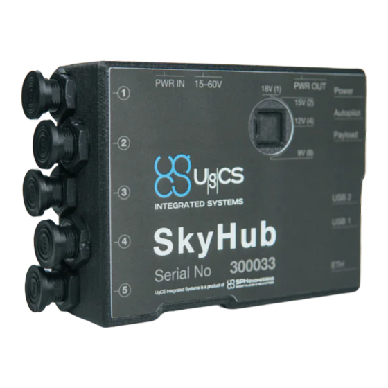
2 • UgCS SkyHub Device UgCS SkyHub User Manual 2 • UgCS SkyHub Device Overview The main device elements are illustrated below. Ethernet connector Communicates with Ethernet-based payloads (see Ethernet) Antenna connector For connecting Wi-Fi/Bluetooth antenna or antenna cable (see... -
Page 11: Specifications
Specifications UgCS SkyHub User Manual Specifications General • DJI M210 / M210 V2 • DJI M600 / M600 Pro Compatible drones • DJI M300 RTK • Custom frames based on DJI A3 flight controller • Pixhawk with ArduCopter / PX4 Temperature range −25°C to +50°C... -
Page 12: Connectors
Connectors UgCS SkyHub User Manual Mechanical Weight 245 g with mountings TTF kit total weight 413 g Connectors Power Input • Mating connector on the cable side: Amass XT30U-F • Voltage range: 15 V to 36 V • Protected against reverse polarity... - Page 13 Connectors UgCS SkyHub User Manual • ESD-protected Pinout (device side) Name Description UART0_TX UART0 transmit line UART0_RX UART0 receive line Ground UART1 Dedicated to communicating with the payload equipped with the UART interface. • Mating connector on the cable side: Lemo FGG.0B.305 •...
- Page 14 Connectors UgCS SkyHub User Manual UART2 Dedicated to communicating with the payload equipped with the UART interface. • Mating connector on the cable side: Lemo FGG.0B.304 • Logic level: 3.3 V • Serial device path: /dev/ttymxc1 • Isolated from the CPU •...
- Page 15 Connectors UgCS SkyHub User Manual I²C Dedicated to communicating with the payload equipped with the I²C interface. • Mating connector on the cable side: Lemo FGG.0B.304 • Logic level: 3.3 V • Isolated from the CPU • ESD-protected Pinout (device side)
-
Page 16: True Terrain Following Kit
True Terrain Following enables the drone to fly at low and constant AGL altitudes (up to 1 meter) without a need to import precise Digital Elevation Model (DEM) height-map into UgCS. Components: •... -
Page 17: Laser Altimeter: Attollo Wasp-200
Laser Altimeter: Attollo WASP-200 UgCS SkyHub User Manual Laser Altimeter: Attollo WASP-200 Attollo WASP-200 is the ultra-compact laser rangefinder device. It is capable to measure the distance quickly and accurately and supports range update rates of up to 56 ranges-per-second with improved accuracy at lower repetition rates with a variety of filtering and averaging features. -
Page 18: Laser Altimeter: Lightware Sf11/C
Laser Altimeter: Lightware SF11/C UgCS SkyHub User Manual Laser Altimeter: Lightware SF11/C LightWare SF11/C LIDAR Range Sensor is a compact, lightweight altimeter for above-ground-level measurement. It supports range update rates of 20 ranges-per-second, includes serial, I²C and USB interfaces. Figure 3.3 — Lightware SF11/C altimeter... -
Page 19: Ground-Penetrating Radar Kit
4 • Ground-Penetrating Radar Kit Ground-penetrating radar (GPR) kit aims to locate underground objects, explore soil layers, for bathymetry purposes. Components: • UgCS SkyHub device with True Terrain Following Kit • Low frequency or high frequency GPR • Cables Low Frequency GPR: Radarteam Cobra Low frequency GPR is more appropriate for detecting large objects, soil profiling, bathymetry. -
Page 20: High Frequency Gpr: Radsys Zond
High Frequency GPR: RadSys Zond UgCS SkyHub User Manual High Frequency GPR: RadSys Zond High frequency GPR it characterized by increased resolution allowing to detect smaller objects. Also, it is more compact and lightweight. The drawback is lower penetrating depth. -
Page 21: Echosounder Kit
UgCS SkyHub User Manual 5 • Echosounder Kit Echosounder kit is designed for bathymetric purposes, detection of underwater objects. Components: • UgCS SkyHub device with True Terrain Following Kit • Echosounder: Echologger ECT400, Echologger ECT D052 or Echologger ECT D032 with housing •... -
Page 22: Echologger Ect D052/D032 Echosounder
Echologger ECT D052/D032 Echosounder UgCS SkyHub User Manual Specifications Temperature range −10°C to +50°C Sensor weight 275 g Total kit weight 1600 g (light housig) 2600 g (heavy housing) Echologger ECT D052/D032 Echosounder Echologger ECT D052/D032 is a ultracompact Dual Frequency Echosounder. -
Page 23: Gas Detector Kit
Optionally gas detector kit can be supplemented with anemometer. Components: • UgCS SkyHub device with or without True Terrain Following Kit • Gas detector: Pergam Laser Falcon or Pergam LMm •... -
Page 24: Gas Detector: Pergam Lmm
Gas Detector: Pergam LMm UgCS SkyHub User Manual Gas Detector: Pergam LMm The LMm (Laser Methane mini) is designed to remotely detect methane, as well as other gas mixtures containing methane (natural gas or similar gases). It allows to quickly and safely find the point of gas leakage by pointing the laser beam at the studied area. -
Page 25: Metal Detector Kit
UgCS SkyHub User Manual 7 • Metal Detector Kit Metal detector kit aims to locate underground metal objects, for geo-research purposes. Components: • UgCS SkyHub device with or without True Terrain Following Kit • Metal detector: Geonics EM-61 • Mounting kit and cable... - Page 26 7 • Metal Detector Kit UgCS SkyHub User Manual Specifications Temperature range −30°C to +60°C Copyright © 2019—2021, SPH Engineering Revision 5 • November 2021...
-
Page 27: Conductivity Meter Kit
8 • Conductivity Meter Kit Conductivity meter kit is designed for exploration in agriculture, archaeology, and general soil sciences are common. Components: • UgCS SkyHub device with or without True Terrain Following Kit • Conductivity meter: Geonics EM38-MK2 • Mounting kit and cable... - Page 28 9 V battery, external 12 battery Device dimensions (L × W 107 x 17 x 8 cm x H) Weight 5.4 kg with mountings and SkyHub Temperature range −40°C to +50°C Copyright © 2019—2021, SPH Engineering Revision 5 • November 2021...
-
Page 29: Remote Water Sampling Kit
UgCS SkyHub User Manual 9 • Remote Water Sampling Kit Remote Water Sampling kit aims … <TODO> Components: • UgCS SkyHub device with True Terrain Following Kit • Water sampler: Ruttner Water Sampler • Mounting kit and cable Water Sampler: Ruttner Water Sampler Ruttner Water Sampler is …... -
Page 30: Optional Sensors
10 • Optional Sensors UgCS SkyHub User Manual 10 • Optional Sensors The kit can be equipped with an optional sensor if the UgCS SkyHub has a free slot. Optional sensors can be also used as the main payload. Optional sensors: •... -
Page 31: Assembling
1. Put the M600 brackets to UgCS SkyHub. Figure 11.1 — UgCS SkyHub with mounting brackets for M600 2. Mount the UgCS SkyHub onto the drone and connect the cables. Copyright © 2019—2021, SPH Engineering Revision 5 • November 2021... - Page 32 UgCS SkyHub User Manual Figure 11.2 — The UgCS SkyHub mounted onto the M600 drone 3. Connect the UgCS SkyHub to the drone’s power outlet (DC-18V) using included power cable. Attention! Do not connect any payload to this connector unless you are sure about the payload’s power voltage range.
- Page 33 11 • Assembling UgCS SkyHub User Manual Figure 11.4 — Connecting the UgCS SkyHub to the flight controller Copyright © 2019—2021, SPH Engineering Revision 5 • November 2021...
-
Page 34: Dji M210 / M210 V2
Figure 11.5 — M210 API and Power connectors 2. Snap the UgCS SkyHub on the right leg of the drone. Figure 11.6 — UgCS SkyHub on the M210 leg Copyright © 2019—2021, SPH Engineering... - Page 35 DJI M210 / M210 V2 UgCS SkyHub User Manual 3. Open the leg brace, slide the UgCS SkyHub up and close the leg brace. Check that the retaining tab is fixed by the leg brace and the brace is closed completely.
- Page 36 DJI M210 / M210 V2 UgCS SkyHub User Manual Figure 11.9 — 3-pin rectangular connector to be plugged into the drone 6. Plug the connector into the drone. The white stripe is on the top. Figure 11.10 — 3-pin rectangular connector plugged into the drone 7.
- Page 37 Figure 11.12 — M210 cable cover installed 9. Make the connections to the UgCS SkyHub. Attention! The data connectors have a different number of pins. Be sure to use the appropriate connectors and to line up the red dots.
- Page 38 DJI M210 / M210 V2 UgCS SkyHub User Manual Figure 11.13 — UgCS SkyHub installed and connected 10. Plug the power cable into the drone. Figure 11.14 — Power cable connected to the M210 11. The installation is complete. The end result is shown on the Figure 11.15...
- Page 39 DJI M210 / M210 V2 UgCS SkyHub User Manual Figure 11.15 — The UgCS SkyHub mounted onto the M210 drone Copyright © 2019—2021, SPH Engineering Revision 5 • November 2021...
-
Page 40: Dji M300 Rtk
UgCS SkyHub User Manual DJI M300 RTK UgCS SkyHub Device 1. DJI M300 RTK TTF kit include UgCS SkyHub with mounting brackets, data and power cable and radio altimeter. Figure 11.16 — DJI M300 RTK UgCS SkyHub TTF kit 2. Snap the UgCS SkyHub on the right leg of the drone. - Page 41 Figure 11.17 — UgCS SkyHub on the M300 leg 3. Connect UgCS SkyHub data and power cable to the drone OSD port. OSD port is placed under rubber cover from the top right drone side. Fix the cable bracket on the top of on M300 with M3 screw.
- Page 42 UgCS SkyHub User Manual Figure 11.18 — UgCS SkyHub data and power cable connected to the M300. 4. Attach altimeter to the right M300 leg under the UgCS SkyHub. Connect 5pin Lemo connector to 5 pin UgCS SkyHub port. Figure 11.19 — Altimeter attached to the M300.
- Page 43 DJI M300 RTK UgCS SkyHub User Manual 5. The installation is complete. The end result is shown on the Figure 11.20 Figure 11.20 — The UgCS SkyHub mounted onto the M300 drone Copyright © 2019—2021, SPH Engineering Revision 5 • November 2021...
-
Page 44: Preparation
Important: It is strongly recommended to switch off a remote controller before any operations with the UgCS SkyHub Wi-Fi. After powering on the UgCS SkyHub operates as Wi-Fi access point with following credentials: • SSID: UgCS-UgCS SkyHub-****** (where ****** is the UgCS SkyHub serial number) •... - Page 45 UgCS SkyHub runs DHCP service onboard, therefore, the PC’s IP address will be assigned automatically after connection. Access to Onboard File System One may use any SCP client to access the UgCS SkyHub file system. For example, one may use WinSCP. Figure 12.1 — WinSCP settings While pressing the Login button one may choose between login via SCP (to have access to the file system) or opening with PuTTY (for SSH access).
-
Page 46: Setup The Ugcs Skyhub Device
UgCS SkyHub User Manual Setup the UgCS SkyHub Device In order to configure the UgCS SkyHub software one should edit skyhub.conf file located in /etc/skyhub/ directory. This configuration file has a widely used INI like file format. The default configuration file created automatically if the configuration file doesn’t exist. - Page 47 Setup the UgCS SkyHub Device UgCS SkyHub User Manual ECHOLOGGER_ECT=false FTTECHNOLOGIES_FT742_SM=false GEONICS_EM_38_MK2=false GEONICS_EM_61=false GNSS=false LIGHTWARE_SF=false NANORADAR_MR=false NANORADAR_NRA=true PAYLOAD_EXAMPLE=false PERGAM_FALCON=false PERGAM_LMM=false RADARTEAM_COBRA=false RADSYS_ZOND=true For a more detailed description of the configuration file, see Configuration Parameters. Copyright © 2019—2021, SPH Engineering Revision 5 • November 2021...
-
Page 48: Setup The Ugcs For Dji Mobile Application
UgCS SkyHub User Manual Setup the UgCS for DJI Mobile Application One should enable custom payload support in the UgCS for DJI mobile application. After starting the application go to Menu > Drone Specific Settings and enable the corresponding checkbox. -
Page 49: Setup Interface To Dji Autopilot
UgCS SkyHub User Manual Setup Interface to DJI Autopilot To allow the UgCS SkyHub to connect to the DJI autopilot, one should activate and setup the Onboard SDK for its device. The following steps are described for the DJI A3 flight controller but may be applied to another DJI product with a minor difference. - Page 50 Setup Interface to DJI Autopilot UgCS SkyHub User Manual Figure 12.4 — DJI Assistant 2 login window 3. Switch on the drone, wait for the device to appear, open the main window, then choose the SDK tab and check Enable API Control and Ground Station Status checkboxes.
- Page 51 Setup Interface to DJI Autopilot UgCS SkyHub User Manual 4. When available: Choose the Basic Settings > Remote Controller tab, check the Enable Multiple Flight Mode checkbox, and configure the flight mode switch to be in P-mode for left and right positions while being in A-mode for the middle position.
- Page 52 Setup Interface to DJI Autopilot UgCS SkyHub User Manual 9. Restart the drone by a power cycle. The UgCS SkyHub device should be properly connected to the flight controller. 10. Wait for the UgCS SkyHub firmware loads and starts. The DJI mobile application may request you about additional permissions for the Onboard SDK.
- Page 53 APP_KEY accordingly in [DJI] section) as described in Setup the UgCS SkyHub Device. Do not forget to restart the UgCS SkyHub after changing parameters. 7. Follow the steps from 1 to 9 from the previous section but using own DJI credentials.
- Page 54 Setup Interface to DJI Autopilot UgCS SkyHub User Manual Important: The DJI flight controller may not activate from the first attempt. If there is no connection with flight controller after full system setup, try to repeat steps from 7 to 9 from the previous section several times with the drone power cycling.
-
Page 55: Setup Interface To Ardupilot
Setup Interface to ArduPilot UgCS SkyHub can be connected to the flight controller flashed with the ArduPilot 4.x.x firmware. 1. Make sure you have the UgCS version 4.3 or higher (download links can be found in Prerequisites section). 2. Configure UgCS Ardupilot VSM that is installed with UgCS. Open vsm-ardupilot.conf in text editor, the file is located in the UgCS installation... -
Page 56: Setup Interface To Px4
UgCS SkyHub User Manual Setup Interface to PX4 UgCS SkyHub can be connected to the flight controller flashed with the PX4 1.10.x or higher firmware. 1. Make sure you have the UgCS version 4.3 or higher (download links can be found in Prerequisites section) and VSM for PX4 is installed. - Page 57 DJI_M=false MAVPILOT=true 5. Restart UgCS SkyHub 6. If SkyHub is connected to telemetry port 2, open application QGroundControl, then go to Parameters -> MAVLink and set parameter MAV_1_CONFIG to TELEM2: Figure 12.13 — UgCS SkyHub PX4 TELEM2 port configuration 7. Restart autopilot.
- Page 58 Setup Interface to PX4 UgCS SkyHub User Manual Figure 12.15 — UgCS SkyHub PX4 TELEM2 port baudrate configuration Note: UgCS SkyHub subscribes to the following MAVLINK messages: GPS2_RAW @ 10 Hz GPS_RAW_INT @ 10 Hz GLOBAL_POSITION_INT @ 10 Hz ATTITUDE @ 10 Hz...
-
Page 59: Payloads Setup
13 • Payloads Setup UgCS SkyHub User Manual 13 • Payloads Setup Choose the usage scenario below: • Altimeter Setup • Nanoradar NRA24 Altimeter Setup • Attollo WASP-200 Altimeter Setup • Lightware SF11/C Altimeter Setup • Ground-Penetrating Radar Setup •... - Page 60 13 • Payloads Setup UgCS SkyHub User Manual MIN_ALTITUDE_M or ascending above MAX_ALTITUDE_M make the drone hover and go to the safe altitude. Another parameter to be set is the sensor’s zero-level above ground when the drone stands at the surface: [ALTIMETER] ZERO_LEVEL_M=0.4...
- Page 61 13 • Payloads Setup UgCS SkyHub User Manual Nanoradar NRA24 Altimeter Setup 1. Set NANORADAR_NRA item to true in [PAYLOADS] section: [PAYLOADS] NANORADAR_NRA=true 2. Choose the appropriate SERIAL_DEVICE in the [NANORADAR_NRA] section depending on which connector it is connected to. Set it to /dev/ttymxc5 when...
- Page 62 LIGHTWARE_SF=true 2. Choose the appropriate CONNECTION_TYPE in the [LIGHTWARE_SF] section depending on which UgCS SkyHub connectors it is used to. Set it to I2C when used connector configured as an I²C interface or to UART when used connector configured as an UART interface:...
-
Page 63: Ground-Penetrating Radar Setup
Ground-Penetrating Radar Setup UgCS SkyHub User Manual Ground-Penetrating Radar Setup Low Frequency GPR Setup 1. Set RADARTEAM_COBRA item to true in [PAYLOADS] section: [PAYLOADS] RADARTEAM_COBRA=true 2. Set MODEL and TIME_RANGE parameters in the [RADARTEAM_COBRA] section according to concrete GPR model used:... - Page 64 Ground-Penetrating Radar Setup UgCS SkyHub User Manual High Frequency GPR Setup 1. Every new device is to be calibrated before using. One should find the appropriate values of the pulse delay. Connect the GPR to the PC, run the Prism 2 software, and find the required pulse delay while using the desired mode, time range, sample count.
- Page 65 Ground-Penetrating Radar Setup UgCS SkyHub User Manual 3. Set the trace time range, sample count, pulse delay, and filter in the corresponding fields in the [RADSYS_ZOND] section: [RADSYS_ZOND] FILTER_1=OFF FILTER_2=OFF MODE=TWO_CHANNELS PULSE_DELAY_1=297 PULSE_DELAY_2=301 SAMPLE_COUNT=256 TIME_RANGE_NS_1=300 TIME_RANGE_NS_2=300 Note: When using the Aero version of RadSys Zond radar, all fields are ignored apart PULSE_DELAY_1 and TIME_RANGE_NS_1.
-
Page 66: Echosounder Setup
Echosounder Setup UgCS SkyHub User Manual Echosounder Setup There are common echosounder settings in the [ECHOSOUNDER] section. Check whether minimum and maximum values correspond to your needs: [ECHOSOUNDER] MIN_DEPTH_M=0.5 MAX_DEPTH_M=20 These values are used to bound valid echosounder depth values. When the depth value is out of the limits, the operator will be notified. - Page 67 Echosounder Setup UgCS SkyHub User Manual 3. Set the MIN_SENSOR_DEPTH_M parameter in the [ECHOLOGGER_ECT] section for data filtering by echosounder depth value while recording. Set to zero for disabling: [ECHOLOGGER_ECT] MAX_SENSOR_ANGLE_DEG=10 MIN_SENSOR_DEPTH_M=0.1 4. Set the RANGE_M, the DEADZONE_MM parameters in the [ECHOLOGGER_ECT] section...
- Page 68 Echosounder Setup UgCS SkyHub User Manual 1. Set ECHOLOGGER_DUAL item to true in [PAYLOADS] section: [PAYLOADS] ECHOLOGGER_DUAL=true 2. Set the MAX_SENSOR_ANGLE_DEG parameter in the [ECHOLOGGER_DUAL] section for data filtering by echosounder tilt while recording. Set to 90 degrees for disabling.
- Page 69 Echosounder Setup UgCS SkyHub User Manual Note the data rate in the ECHOSOUNDER mode is significantly lower than in the NMEA one. Strongly recommended to set the FREQUENCY_HZ value in the ECHOLOGGER_DUAL section according to the table: Table 13.2 — Maximum data rate against range in NMEA and Echosounder mode for Echologger ECT...
-
Page 70: Gas Detector Setup
Gas Detector Setup UgCS SkyHub User Manual Gas Detector Setup There are common gas detector settings in the [GAS_DETECTOR] section. Check whether minimum and maximum values correspond to your needs: [GAS_DETECTOR] MIN_CONCENTRATION_PPM=0 MAX_CONCENTRATION_PPM=1000 These values are used to bound valid gas detector values. When the gas concentration is out of the limits, the operator will be notified. -
Page 71: Metal Detector Setup
Metal Detector Setup UgCS SkyHub User Manual 2. Choose the appropriate SERIAL_DEVICE in the [PERGAM_LMM] section depending on which connector it is connected to. Set it to /dev/ttymxc5 when connecting to the 5-pin Lemo connector (see UART1) or to /dev/ttymxc1 when connecting to the... -
Page 72: Conductivity Meter Setup
CONNECTION_TYPE=RS232 ; connection through RS323 3. Choose the appropriate CHANNEL_NUMBER in the [GEONICS_EM_38_MK2] section to display the desired value on the Conductivity Meter widget in UgCS-CPM. For example, to display the conductivity for 1.0 m set channel to 3: [GEONICS_EM_38_MK2]... -
Page 73: Remote Water Sampling Setup
1. Set DROP_MESSENGER item to true in [PAYLOADS] section: [PAYLOADS] DROP_MESSENGER=true 2. DROP_MESSENGER plugin has only one purpose is to drop messenger to close Ruttner water sampler. UgCS SkyHub drops the messenger using servo controlled through PWM. By default, it’s used the following PWM settings: [DROP_MESSENGER] SERVO_LOCK_PULSE_MS=1.5 SERVO_PERIOD_MS=10 SERVO_UNLOCK_PULSE_MS=0.5... -
Page 74: Obstacle Detector Setup
1. Set GNSS item to true in [PAYLOADS] section: [PAYLOADS] GNSS=true Important: GPS Receiver loads settings from separate config file. The file location: /etc/skyhub/gnss.conf. File format: INI (https://en.wikipedia.org/wiki/INI_file) GPS Receiver Configuration to find all available settings with default values and descriptions. - Page 75 Obstacle Detector Setup UgCS SkyHub User Manual 1. Set OUTPUT_GPS item to true in [OUTPUTS] section: [OUTPUTS] OUTPUT_GPS=true 2. Choose the appropriate ADDRESS in the [OUTPUT_GPS] section. ADDRESS has to match with connected serial device name which the GPS output sends messages to.
-
Page 76: Getting Started
Disconnect from the UgCS SkyHub. 2. Start the PC and connect it to the Wi-Fi network. Start the UgCS and plan a mission for the drone. 3. Turn on the drone, the payload, and UgCS SkyHub device. - Page 77 14 • Getting Started UgCS SkyHub User Manual 6. Make sure that the drone with a correct profile appears in the UgCS on the PC and all drone indicators (battery, uplink, downlink, satellites) are green. Select the drone and the mission.
- Page 78 6. Connect both the PC and the mobile device to the same Wi-Fi network. 7. Switch on the drone and the DJI Remote Controller. Make sure the flight mode switch is in P-mode. Run UgCS, UgCS for DJI, and make sure the drone has a good status in UgCS.
-
Page 79: Grasshopper Mode
Grasshopper Mode UgCS SkyHub User Manual 15. Take off using the DJI Remote Controller or from the UgCS and rise up to the appropriate altitude (see limits from step 2). 16. Press the Activate button in the Terrain Following widget to start the flight in terrain-following mode. - Page 80 Grasshopper Mode UgCS SkyHub User Manual 2. Start the PC and connect it to the Wi-Fi network. Start the UgCS and plan a mission for the drone. The descent points must be set as wait action, the wait duration defines waiting time in the descent point.
- Page 81 6. Connect both the PC and the mobile device to the same Wi-Fi network. 7. Switch on the drone and the DJI Remote Controller. Make sure the flight mode switch is in P-mode. Run UgCS, UgCS for DJI, and make sure the drone has a good status in UgCS.
-
Page 82: Obstacle Avoidance Mode
Obstacle Avoidance mode is enabled for all supported DJI drones. Description The mode can be activated by pressing the Activate button on the Obstacle Avoidance widget in UgCS-CPM. The activation status is kept in config (see the ACTIVATED parameter in the [OA] section in config Obstacle Avoidance... - Page 83 (see details in Obstacle Avoidance Configuration). Disconnect from the UgCS SkyHub. 2. Start the PC and connect it to the Wi-Fi network. Start the UgCS and plan a mission for the drone. 3. Turn on the drone, payloads, and UgCS SkyHub device.
-
Page 84: About Log Files
11. Press the Activate button, if the mode is deactivated. Wait for the Obstacle Avoidance ACTIVATED message. 12. Upload the route to the drone using UgCS, launch auto, TTF, or Grasshopper Flight mode or start manual flight. 13. If the distance to obstacles drops below the Safe Distance (see step 9), the safety action will be activated. - Page 85 (in YEAR-MONTH-DAY-HOUR-MIN-SEC format) after the synchronization with the GPS. The time is UTC. Logging (except system log) is started only by command from UgCS-CPM (using the Record/Stop button) or automatically after taking off. The system log begins after onboard software is started.
- Page 86 About Log Files UgCS SkyHub User Manual Position Log Position logs contain common parameter group and the payload’s specific parameters if any. Common parameter columns fill in with the latest received value. Specific parameter columns fill in at the moment when the payloads received data, excluding altimeters, its columns write as common parameters If payloads don’t receive data during doubled period sets in the...
- Page 87 About Log Files UgCS SkyHub User Manual Colunm name Unit Description Altitude AMSL received from the drone Altitude RTK using RTK station Table 14.2 — Position Log. Anemometer Columns Description Colunm name Unit Description Anemometer AIR:Speed Measured wind speed Measured wind direction relative to...
- Page 88 About Log Files UgCS SkyHub User Manual Colunm name Unit Description Measured depth on high acoustic ECHO:Depth Hi frequency. Support for dual frequency echosounder Measured depth on low acoustic ECHO:Depth Lo frequency. Support for dual frequency echosounder Depth with taking into account sensor position relative to the waterline.
- Page 89 About Log Files UgCS SkyHub User Manual Table 14.6 — Position Log. Gas Detector Columns Description Colunm name Unit Description Gas Detector Measured concentration in ppm (parts GAS:Methane ppm x m per million) per meter Specific status for the payload •...
- Page 90 About Log Files UgCS SkyHub User Manual Colunm name Unit Description GPS Quality Indicator • 0: fix not available • 1: GPS fix • 2: Differential GPS fix • 3: PPS fix GNSS:Quality Indicator • 4: RTK • 5: float RTK •...
- Page 91 About Log Files UgCS SkyHub User Manual Table 14.10 — Position Log. Obstacle Detector Columns Description Colunm name Unit Description Obstacle Detector Distance to the nearest obstacle in the OBS:Sector1 sector 1 Distance to the nearest obstacle in the OBS:Sector2...
-
Page 92: Log Files Management
Wi-Fi) or by wire (see Connect to UgCS SkyHub Using Ethernet). 2. Go to Settings > UgCS SkyHub and make sure the IP-address corresponds to the connection way. 3. Open UgCS-CPM and go to Tools > Manage Logs. 4. Press the Browse button to choose the destination folder for log files. - Page 93 Log Files Management UgCS SkyHub User Manual Figure 14.4 — UgCS-CPM. Manage Logs window Copyright © 2019—2021, SPH Engineering Revision 5 • November 2021...
-
Page 94: Update Firmware
Ethernet). 2. Open UgCS-CPM and go to Tools > Manage UgCS SkyHub 3. The UgCS SkyHub (Aux) indicator is green when there is the connection to the UgCS SkyHub device via Ethernet or Wi-Fi and red otherwise. 4. The latest UgCS SkyHub firmware compatible with the installed UgCS-CPM is located in UgCS-CPM/firmware folder. -
Page 95: Uninstall Firmware
3. Upload manually the firmware to MicroSD root (path: /run/media/mmcblk1p1) by FTP/SCP client. 4. Connect to UgCS SkyHub via ssh and move to the MicroSD root. 5. Unpack the firmware package and manually run the script to uninstall the UgCS SkyHub firmware from the device: $ tar -xvf skyhub-armhf-*.tar.gz... -
Page 96: Configuration Parameters
15 • Configuration Parameters • Configuration file location: /etc/skyhub/skyhub.conf • File format: INI (https://en.wikipedia.org/wiki/INI_file) Important: The UgCS SkyHub device should be restarted after any change in the configuration file by reboot command or by power cycling. UgCS SkyHub Configuration Table 15.1 — UgCS SkyHub settings... - Page 97 15 • Configuration Parameters UgCS SkyHub User Manual Default Parameter Description Value Using the DJI autopilot except for false support for DJI M300 RTK. Set to true if DJI drone is used. Using the DJI autopilot to support DJI M300 RTK.
- Page 98 GPR. Set to true if used. Using the RadSys Zond-12e high RADSYS_ZOND false frequency GPR. Set to true if used. Table 15.2 — UgCS SkyHub advanced settings Default Parameter Description Value [APP] Log the debug info to the system log...
-
Page 99: Autopilot Configuration
Autopilot Configuration UgCS SkyHub User Manual Autopilot Configuration DJI Autopilot Configuration Table 15.3 — DJI autopilot settings Default Parameter Description Value [DJI] APP_ID 1071019 DJI App ID APP_KEY 42873…30b25 DJI App Key BAUD_RATE 230400 UART baud rate, bps RESPONSE_TIMEOUT_S DJI response timeout, s... - Page 100 Autopilot Configuration UgCS SkyHub User Manual Default Parameter Description Value SYSTEM_ID MAVLink system Id of UgCS SkyHub TELEMETRY_RATE Telemetry frequency, Hz Using MAVLink V2_EXTENSION V2_EXTENSION false messages. Set to true to enable it. Copyright © 2019—2021, SPH Engineering Revision 5 • November 2021...
-
Page 101: Flight Control Mode Configuration
Flight Control Mode Configuration UgCS SkyHub User Manual Flight Control Mode Configuration True Terrain Following Configuration Table 15.5 — TTF settings Default Parameter Description Value [TF] • ALTIMETER: Use external altimeter as altitude source ALTITUDE_SOURCE ALTIMETER • AUTOPILOT: Use autopiot as... - Page 102 Flight Control Mode Configuration UgCS SkyHub User Manual Default Parameter Description Value [OA] Safety action if the obstacle detected • RETURN_TO_HOME: Activate return to home function RETURN_TO_H ACTION • WARNING: Show warning message • NOTHING: Do nothing Activate or deactivate Obstacle...
- Page 103 Flight Control Mode Configuration UgCS SkyHub User Manual Navigation Configuration Table 15.8 — Navigation settings Default Parameter Description Value [NAV] Radius of waypoint neighborhood in ACCEPTANCE_RADIUS_M which it is considered the vehicle reached the waypoint, m HORIZONTAL_ACCEL_MSS Horizontal acceleration, m/s²...
- Page 104 Flight Control Mode Configuration UgCS SkyHub User Manual Default Parameter Description Value Defines a proportional gain that compensates for an error between horizontal target and actual velocities. Recommend to use 0 for most vehicles. Available range is from 0.0 to 1.0.
-
Page 105: Altimeter Configuration
Altimeter Configuration UgCS SkyHub User Manual Altimeter Configuration Table 15.9 — Common altimeter settings Default Parameter Description Value [ALTIMETER] MAX_ALTITUDE_M Max altitude value, m MIN_ALTITUDE_M Min altitude value, m Altimeter position above ground level, ZERO_LEVEL_M Maximum number of ignoring fails... - Page 106 Altimeter Configuration UgCS SkyHub User Manual Nanoradar NRA24 Altimeter Configuration Table 15.10 — Nanoradar NRA24 altimeter settings Default Parameter Description Value [NANORADAR_NRA] Averaging factor. The more is the AVERAGING smoother but rarer. BAUD_RATE 115200 UART baud rate, bps UART serial device: •...
- Page 107 Altimeter Configuration UgCS SkyHub User Manual Lightware SF11/C Altimeter Configuration Table 15.12 — Lightware SF11/C altimeter settings Default Parameter Description Value [LIGHTWARE_SF] Connection type: • I2C for I²C connection CONNECTION_TYPE • UART for serial connection I²C device address in hexadecimal...
-
Page 108: Gpr Configuration
GPR Configuration UgCS SkyHub User Manual GPR Configuration Low Frequency GPR Configuration Table 15.13 — Low Frequency GPR settings Default Parameter Description Value [RADARTEAM_COBRA] Bluetooth name of GPR device. May be BLUETOOTH_NAME RT[0-9]+ a regular expression. GPR model. Added to the SEG-Y log... - Page 109 GPR Configuration UgCS SkyHub User Manual Default Parameter Description Value GPR channel mode: • CHANNEL_1: Single-channel, the first channel is active • CHANNEL_2: Single-channel, the second channel is active • TWO_CHANNELS: Dual-channel, both channels are active MODE CHANNEL_1 • TX1_RX2: The first channel...
- Page 110 GPR Configuration UgCS SkyHub User Manual Default Parameter Description Value Possible values are: • SOUNDING: Normal operation mode • CALIBRATION: Sine wave with SOUNDING_MODE SOUNDING frequency 20 MHz • TEST: Sine wave with constant period for any settings Sample count per trace:...
-
Page 111: Echosounder Configuration
Echosounder Configuration UgCS SkyHub User Manual Echosounder Configuration Table 15.15 — Common echosounder settings Default Parameter Description Value [ECHOSOUNDER] CABLE_LENGTH_M Echosounder cable length, m MAX_DEPTH_M Max depth value, m MIN_DEPTH_M Min depth value, m Echologger ECT400 Configuration Table 15.16 — Echologger ECT400 settings... - Page 112 Echosounder Configuration UgCS SkyHub User Manual Default Parameter Description Value Data filtering by sensor dept in the water. Sensor depth is calculated as a difference between the length of the MIN_SENSOR_DEPTH_M cable (set by CABLE_LENGTH_M parameter in the ECHOSOUNDER section) and current altitude.
- Page 113 Echosounder Configuration UgCS SkyHub User Manual Default Parameter Description Value BAUD_RATE 115200 UART baud rate, bps Near field zone where detection is DEADZONE_HIGH_MM ignored for high acoustic frequency, Near field zone where detection is ignored for low acoustic frequency, DEADZONE_LOW_MM 1000 mm.
- Page 114 Echosounder Configuration UgCS SkyHub User Manual Default Parameter Description Value Measuring range for high acoustic frequency, m. Only fixed ranges are RANGE_HIGH_M available: 1, 1.5, 2, 3, 5, 10, 15, 20, 30, 40, 50, 60, 70, 80, 90, 100, 120, 150, 200...
-
Page 115: Gas Detector Configuration
Pergam Laser Falcon board and can be sent upon request. The stored information is updated every 500 ms. The FREQUENCY_HZ parameter only sets the frequency of requests from SkyHub to the Pergam Laser Falcon, while the Pergam Laser Falcon continues to work according to its scheme. - Page 116 Gas Detector Configuration UgCS SkyHub User Manual Default Parameter Description Value [PERGAM_LMM] Measuring frequency, Hz. Available FREQUENCY_HZ values: 2 Hz, 1 Hz, or lower. UART serial device: • /dev/ttymxc5 for UART1 (5-pin) SERIAL_DEVICE /dev/ttymxc5 • /dev/ttymxc1 for UART2 (4-pin) Copyright © 2019—2021, SPH Engineering...
-
Page 117: Metal Detector Configuration
Metal Detector Configuration UgCS SkyHub User Manual Metal Detector Configuration Table 15.21 — Common metal detector settings Default Parameter Description Value [METAL_DETECTOR] MAX_OUTPUT_VALUE_MV 1000 Max output metal detector value, mV MIN_OUTPUT_VALUE_MV Min output metal detector value, mV Geonics EM-61 Configuration Table 15.22 —... -
Page 118: Conductivity Meter Configuration
Conductivity Meter Configuration UgCS SkyHub User Manual Conductivity Meter Configuration Table 15.23 — Common conductivity meter settings Default Parameter Description Value [CONDUCTIVITY_METER] MAX_OUTPUT_VALUE_MS_M Max altitude value, mS/m MIN_OUTPUT_VALUE_MS_M Min altitude value, mS/m Geonics EM38-MK2 Configuration Table 15.24 — Geonics EM38-MK2 settings... -
Page 119: Drop Messenger Configuration
Drop Messenger Configuration UgCS SkyHub User Manual Drop Messenger Configuration Table 15.25 — Pergam Laser Falcon settings Default Parameter Description Value [DROP_MESSENGER PWM pulse width to lock the drop SERVO_LOCK_PULSE_MS messenger, ms. SERVO_PERIOD_MS PWM signal period, ms. PWM pulse width to unlock the drop SERVO_UNLOCK_PULSE_MS messenger, ms. -
Page 120: Anemometer Configuration
Anemometer Configuration UgCS SkyHub User Manual Anemometer Configuration Table 15.26 — Common anemometer settings Default Parameter Description Value [ANEMOMETER] MAX_WIND_SPEED_MPS Max wind speed value, m MIN_WIND_SPEED_MPS Min wind speed value, m FT Technologies FT742-SM Configuration Table 15.27 — FT Technologies FT742-SM settings... -
Page 121: Gps Receiver Configuration
GPS Receiver Configuration UgCS SkyHub User Manual Default Parameter Description Value SERIAL_DEVICE /dev/ttymxc1 UART serial device GPS Receiver Configuration Table 15.29 — GPS Receiver settings Default Parameter Description Value [NANORADAR_MR] BAUD_RATE 115200 UART baud rate, bps DATE_FORMAT yyyy/MM/dd Data format in... - Page 122 GPS Receiver Configuration UgCS SkyHub User Manual Default Parameter Description Value START_DELAY_S Start delay, s Copyright © 2019—2021, SPH Engineering Revision 5 • November 2021...
-
Page 123: Legal Notice
Trademarks UgCS is a registered trademark of SPH Engineering. All other trademarks and registered trademarks mentioned in this document are the property of their respective owners.
Need help?
Do you have a question about the SkyHub and is the answer not in the manual?
Questions and answers