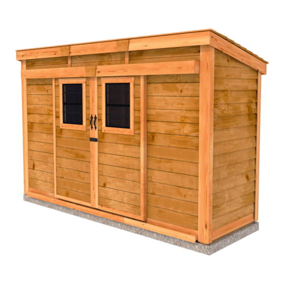
OLT 12x4 GardenSaver Shed Assembly Manual
Slider ak bevel model with metal roof
Hide thumbs
Also See for 12x4 GardenSaver Shed:
- Assembly manual (37 pages) ,
- Assembly manual (35 pages)
Advertisement
Quick Links
Version #1.8
May 5, 2021
Stock Code:
GS124-Slider-AK-Metal
Thank you for purchasing a
12x4 GardenSaver Shed with
Sliding Double Doors. Please take
the time to identify all the parts
prior to assembly.
Safety Points and Other Considerations
Our products are built for use based on
proper installation on level ground and
normal residential use. Please follow the
instruction manual when building your
shed and retain the manual for future
maintenance purposes.
Customers are responsible for ensuring
a solid, level, well-draining site for
construction.
Please check with your local municipal
or county by-laws before ordering this
product to confirm it complies with
building codes.
In the event of a missing or broken piece, call the Outdoor Living Today Customer Support Line @ 1-888-658-1658 with-
in 30 days of the delivery of your purchase. It is our commitment to you to courier replacement parts, free of charge,
within 10 business days of this notification. Replacement parts will not be provided free of charge after the 30 day
grace period.
All structures purchased from Outdoor Living Today are covered for a period of one year for defects in manufacturing
and workmanship. Costs incurred for customer installations are not included.
Failure to use supplied parts included in this kit could result in poor product performance and may void your warranty.
Please contact Outdoor Living Today's Customer Toll Free Line if you plan to deviate from our written instructions.
1-888-658-1658
12x4 GardenSaver Shed - Slider
AK Bevel Model with Metal Roof
Assembly Manual
- Snow load ratings vary by geographical location. If heavy or wet snowfall occurs, it
is advisable to sweep snow off roof frequently.
- If the product is elevated, any structural and building code requirements are solely
the customer's responsibility, and should be abided by.
- In areas with high or gusty wind conditions, it is advisable to install the structure
securely to the ground.
- Have a regular maintenance plan to ensure screws, doors, windows and parts are
tightly affixed.
Customer agrees to hold Outdoor Living Today and any Authorized
Dealers free of any liability for improper installation, maintenance and
repair.
www.outdoorlivingtoday.com
Page 1
sales@outdoorlivingtoday.com
Advertisement

Related Manuals for OLT 12x4 GardenSaver Shed


Summary of Contents for OLT 12x4 GardenSaver Shed
- Page 1 12x4 GardenSaver Shed - Slider AK Bevel Model with Metal Roof Assembly Manual Version #1.8 May 5, 2021 Stock Code: GS124-Slider-AK-Metal Thank you for purchasing a 12x4 GardenSaver Shed with Sliding Double Doors. Please take the time to identify all the parts prior to assembly.
- Page 2 1. Floor Section Parts List - Pages 2, 3, and 4 Steps Floors 1A: 2 - 45 ½” x 70 ¾” - Floor Frames 1B: 4 - 1 ½” x 3 ½” x 67 3/4” - Floor Joists 1C: 2 - 1 ½” x 3 ½” x 45 ½” - Floor Runners - Short 1CC: 5 - 1 ½”...
- Page 3 4. Trim & Miscellaneous Section Steps Bottom Skirting & Top Wall Trim 45-48 4A: 5 - ¾” x 4 ½” x 45 ¼” - Side/Rear Bottom Skirting (Bevel Siding) 4B: 3 - ½” x 4 ½” x 45 ¼” - Front Bottom Skirting 4BB: 3 - ¾”...
-
Page 4: Tools Required
12X4 GardenSaver Shed with Sliding Double Doors and Metal Roof HARDWARE PACKAGE BR1 - Square Drive Bit BT2 - Torx Drive Bit x 330 N1 - 1 1/2” Finishing Nails ST1 - 1 1/2” Torx Screws Y35 - Roller Assembly S5 - 4”... - Page 5 What Can I Do Before My Shed Arrives? Before starting your project become familiar with this assembly manual and determine if you can complete the project yourself or will require a professional contractor. Please note that certain counties and municipalities require building permits prior to installation. We recommend to all consumers that they check with their local county/municipality for these specifics prior to purchasing any of our products since this is your sole responsibility.
-
Page 6: Floor Section
Exploded view of all parts necessary to complete 1. Floor Section Floor Section. Identify all parts prior to starting. Note: Floor Footprint is 141 1/2” wide x 45 1/2” deep. Floor Frames - 2pcs. Plywood Floor - 2pcs. (Part 1A) (Part 1D) Center Floor Joists - 4pcs. - Page 7 Parts Hardware Position 1C - Floor Runners - Short on each 1C - Floor Runners - Short S1 - 2 1/2” Screws side of the completed floor frame. Runners should (1 1/2” x 3 1/2” x 45 1/2”) x 2 x 8 total be flush with corners but not overhanging.
- Page 8 Advice: Use chalk line to mark location of mid joists for interior screws. Hardware With Plywood positioned correctly on floor framing, attach with 1 1/4” Screws. S2 - 1 1/4” Screws Use screws every 16” around perimeter of each floor section and 3 screws x 40 total (approx.) through each mid joists.
- Page 9 Ensure bottom plate is flush side-to-side You can find BR1 - with wall studs Square Drive Bit for the screws in with the Hardware Kit Bag. Bottom Wall Plate Parts Hardware Carefully lay 2AA - Side/Rear Wall Panels face 2AA - Side/Rear Wall Panels S1 - 2 1/2”...
- Page 10 Optional - Caulking seams will help prevent moisture from entering at seam. Caulking not Pilot Hole included in kit. first. Hardware (Steps 10 - 12) Position rear solid wall into place on plywood floor. Butt both vertical wall S1 - 2 1/2” Screws studs of side and rear walls together and attach with 3 - 2 1/2”...
- Page 11 Wall panel will sit flush with floor framing. Do Not Attach Walls To Floor Until Step 24 Complete remaining side wall attachment as per Steps 10 - 11. Ensure bottom plate is flush side-to-side with wall studs. Parts Carefully lay 2BA - Front Wall Panels face down. Position and attach 2BA - Front Wall Panels 2BB - Bottom Wall Plates to bottom of wall studs of each wall panel with (35”...
- Page 12 Step to front and top. Align flush Door Header outside with overhangs wall siding. inside wall framing by 1/2”. Parts (Step 14 - 15) Hardware (Step 14 - 15) Position 2C - Door Header - Short on top 2C - Door Headers - Short S4 - 3”...
- Page 13 Top Siding Pc. for Angle Wall Top Siding Pc. can also be installed after Roof is attached after Step 44. Parts Position 2F - Top Triangular Siding Piece onto 2G - Angle Wall Extenders - L/R 2G - Angle Wall Extender and align as shown above. Attach with (2G - 45 1/2”...
- Page 14 Complete opposite Angled Wall Extender positioning and attachment as per Step 18. Cleat protects overhanging siding on upper walls from damage. Please remove before installing. Protective cleat Siding overhang framing aligned rests in notch. in front. Framing flush along top. Parts Place 2H - Extender Walls on top of Door Header so that framing is 2H - Extender Walls...
- Page 15 Parts Hardware With Extender Walls attached, position 2I - Extender Wall Cleats S1 - 2 1/2” Screws 2I - Extender Wall Cleats in the lower section of (1 1/2” x 2 1/2” x 42 3/8”) x 3 x 9 total each Extender Wall.
- Page 16 Advice: Use Interior Door Header to confirm doorway opening is 66 1/2” wide at top and bottom. Parts Hardware Attach 2E - Interior Door Header as shown above. 2E - Interior Door Header S1 - 2 1/2” Screws Align with top framing of front walls. Attach with (1 1/2”...
- Page 17 Optional - Caulking seams will help prevent moisture from entering at seam. Caulking not included in kit. Hardware To complete Wall Section, attach bottom 2x3 wall plates to plywood floor with S1 - 2 1/2” Screws 2 - 2 1/2” Screws per wall section. Prior to securing, make sure wall panels are x 28 total aligned correctly on the floor.
- Page 18 Note: We recommend you drill a 1/8” pilot hole for each screw, to avoid Screw Front Soffits to splitting wood. The hole depth should be equal to 3/4 the length of screw. Rafters with 2 - 1 1/4” Screws per rafter end. Screw Rear Soffits to Rafters with 2 - 1 1/4”...
- Page 19 Rafter ends vertical. Side View Carefully flip completed Rafter Section over so Front Soffit is facing the front and place on GardenSaver walls. Note: Double check that your Rafter Section is positioned correctly by ensuring the ends of the Rafters are sloped vertically as shown above. Back cut rafter to Rafter sits the back.
- Page 20 90° Metal Brackets Hardware With Rafter Section correctly aligned, secure rafters to walls using Y2 - 90° Metal Bracket 2 - 90° Metal Brackets per side. Attach each brackets with 4 - 1 1/4” Screws. x 4 total Screw into Wall Extender framing at the front and Wall Panel top framing at S2 - 1 1/4”...
- Page 21 1/8” back from Rafter end. Overhanging 2” on outside Rafter. Parts (Steps 32 - 34) Parts (Steps 32 - 36) Locate first first row of Roof Battens. Position 3G - Roof Battens - Outer 3D - Batten Spacers on rear of roof Rafters. Place 1/8” back from end of (3/4”...
- Page 22 Position and attach 2nd row of Battens flush to Batten Spacers as per Step 32. Position and attach 2 remaining Batten Spacers as per Step 33 with 2 - 1 1/4” screws per spacer (4 total). Position and attach 3rd row of Battens as per Step 32. Position Battens flush to Batten Spacers from Step 35.
- Page 23 Parts Hardware Center Facia Nailing Strip (underneath outside of each 3J - Nailing Strips S2 - 1 1/4” Screws batten. Attach with 3 - 1 1/4” Screws evenly spaced into the (3/4” x 3/4” x 51”) x 2 x 6 total batten.
- Page 24 3/4” Overhang Overhang the Metal Roof Panels past the Battens on the sides by approximately 3/4”. The overhang on front and back will be set by the Metal Roof Hangers, but should be approximately 1” on the front and approximately 4” on the back. Metal roof Panels should overlap each other.
- Page 25 Bead of Caulking Once Metal Roof is spaced correctly from side-to-side and top-to-bottom, lift panels up and run a bead of caulking down the overlapping seams of each panel to seal the joints. You will likely need assistance from a helper in this step. Loosely attach middle row before removing Metal Roof Hangers.
- Page 26 Remove Metal Before fully fastening Metal Roof Roof Hangers Panels down, remove the Metal Roof Hangers and insert Foam Enclosures between Metal Roof Panels and Battens at the rear/bottom. Enclosures will prevent moisture and unwanted bugs, etc from entering your shed from here. Parts Foam Enclosures x 4 total Insert Foam...
- Page 27 4. Trim & Miscellaneous Section Exploded view of all parts necessary to complete the Skirting, Trim, Facia and Miscellaneous Pieces. Identify all parts prior to starting. Track Overlay System (Parts 4KA & 4KB & 4KC & 4KD) Front Facia - L/R Trim Detail Rear Middle (Part 4S)
- Page 28 Parts (Steps 45 - 46) Attach 4A - Side/Rear Bottom Skirting around the base 4A - Side/Rear Bottom Skirting - Bevel of the shed. Skirting will hide floor framing. Start with side (3/4” x 4 1/2” x 45 1/4”) x 5 skirting pieces first and attach with 4 - 1 1/2”...
- Page 29 Parts Trim out Rear Walls by attaching Top Wall Trim. Position 4BB - Top Wall Trims with thick end of Bevel downward at top wall, tight against (3/4” x 1 1/2” x 45 1/4”) x 3 Soffits. Attach with 4 - 1 1/2” Finishing Nails per piece. Hardware N1 - 1 1/2”...
- Page 30 33 1/4” Attach 1 Torx Screw per bracket to hold in place while aligning other track. Bottom of bracket flush with bottom of Interior Door Header. Parts Position 4E - Aluminum Door Tracks so they meet in the center of 4E - Aluminum Door Tracks the doorway and with the pre-installed brackets fitting evenly on Door Headers.
- Page 31 Twist Roller Cart onto bolt. After doors are hung, you may need to adjust this until doors hang straight up and down at equal height. Parts Locate all four Y35 - Roller Assemblies. Before attaching to top of 4F - Sliding Doors doors, assemble the units as shown above.
- Page 32 1/4” Gap Lower Door Track Parts Locate 4G - Door Tracks and 4IA - Door Stops. Middle Door Stop 4G - Lower Door Track shoud be centered on shed and outer Door Stops should be 1 1/2” from (1 1/2” x 2 1/2” x 61 1/8) x 2 edge of bottom skirting.
- Page 33 Door Stop and Track Cover are flush Parts Hardware Locate 4HA - Door Track Covers. Lineup so 4HA - Lower Door Track S1 - 2 1/2” Screws Track Covers are flush with Door Stops. This creates Cover x 12 total an enclosure so doors can not slide out of the track.
- Page 34 Right Side Left Side Door Door Door Flange attaches to Left Side Door. Flush with inside of door frame. Parts Position 4J - Interior Door Flange on the rear of the left side 4J - Interior Door Flange door (when viewed from the front of the shed). Ensure flange is flush (3/4”...
- Page 35 Centered above Aluminum Tracks. Bottom of overlay should touch tip of bolts. Parts (Steps 56 - 57) Hardware (Steps 56-57) Install both 4KA - Track Overlay - Top 4KA - Track Overlay - Top S5 - 4” Screws pieces above the aluminum tracks. Position (1 1/2”...
- Page 36 Parts Position 4KD - Track Overlay - Sill pieces evenly on top of Track 4KD - Track Overlay - Sill (Bevel) Overlay with the slope facing away from the shed. This will prevent (1/2” x 4 1/4” x 44 1/4”) x 3 rainwater from collecting on top.
- Page 37 Parts Hardware To complete trimming out rear corners, 4N - Rear Corner Trims N1 - 1 1/2” Finishing Nails locate 4N & 4O - Rear Corner Trims. Align (1/2” x 5 1/2” x 78 1/2”) x 2 x 32 total and attach as per Step 59.
- Page 38 Parts Hardware Attach 4Q - Front Middle Trims above doors 4Q - Front Middle Trim N1 - 1 1/2” Finishing Nails where front wall extenders come together above (1/2” x 2 1/2” x 7 1/2”) x 2 x 6 total track.
- Page 39 Attach other Front and Side Facia to opposite corner as per Step 63. Small gaps may occur. Attach 4T - Front Facia - Center to rafter ends as shown above. Small gaps may occur between the Center and Left/Right Facia, but these will be covered by the Front Metal Drip Cap in Step 68. Attach with 2 - 1 1/2”...
- Page 40 Parts Attach 4U - Trim Detail Plates to cover seams. Two Plates will 4U - Trim Detail Plates cover seams where Rear Facia pieces meet, attach these with 4 - 1 1/2” (5 1/2” high) x 3 Finishing Nails per piece. One more Trim Plate will cover the seam of Hardware the Track Overlay, attach with 3 - 1 1/2”...
- Page 41 caulk in siding gap at top. caulk in siding Requires a large channel on both amount. sides of window. Parts Locate 4W - Window Inserts. Before installing, dab caulk in siding channel 4W - Window Inserts on both sides of window opening. This will prevent water from getting in behind (18 1/4”...
- Page 42 Congratulations on assembling your 12x4 GardenSaver Shed with Sliding Double Doors! Note: Our Sheds are shipped as unfinished products. If exposed to the elements, the western red cedar lumber will weather to a silvery-gray color. If you prefer to keep the cedar lumber looking closer to the original color, we suggest that you treat the wood with a good oil base wood stain.
Need help?
Do you have a question about the 12x4 GardenSaver Shed and is the answer not in the manual?
Questions and answers