Advertisement
Quick Links
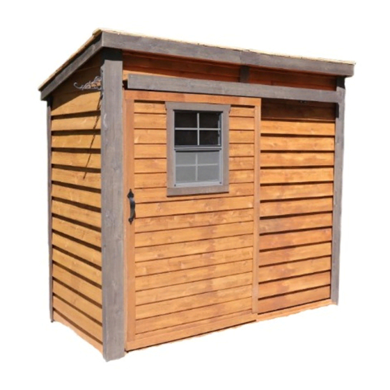
Thank you for purchasing
a 8x4 GardenSaver Shed
with Sliding Door. Please
take the time to identify all
the parts prior to assembly.
Please be aware that it is the
customers' sole responsibility
to acquire the necessary
building permits and or obtain
approval from their local
county, municipality or HOA
prior to purchasing. Generally,
shed structures under 100
square feet do not require
permits in most jurisdictions
in the United States and
Canada.
In the event of a missing or broken piece, call the Outdoor Living Today Customer Support Line @ 1-888-658-1658 with-
in 30 days of the delivery of your purchase. It is our commitment to you to courier replacement parts, free of charge,
within 10 business days of this notification. Replacement parts will not be provided free of charge after the 30 day
grace period.
All structures purchased from Outdoor Living Today are covered for a period of one year for defects in manufacturing
and workmanship. Costs incurred for customer installations are not included.
Failure to use supplied parts included in this kit could result in poor product performance and may void your warranty.
Please contact Outdoor Living Today's Customer Toll Free Line if you plan to deviate from our written instructions.
Outdoor Living Today
8x4 GardenSaver Shed with
- Snow load ratings vary by geographical location. If heavy or wet snowfall occurs, it
is advisable to sweep snow off roof frequently.
- If the product is elevated, any structural and building code requirements are solely
the customer's responsibility, and should be abided by.
- In areas with high or gusty wind conditions, it is advisable to install the structure
securely to the ground.
- Have a regular maintenance plan to ensure screws, doors, windows and parts are
tightly affixed.
Customer agrees to hold Outdoor Living Today and any Authorized
Dealers free of any liability for improper installation, maintenance and
repair.
www.outdoorlivingtoday.com
Page 1
Sliding Door
Assembly Manual
Stock Code
GS84-Slider
sales@outdoorlivingtoday.com
Revision #1.3
July 14, 2020
Advertisement

Related Manuals for OLT GardenSaver GS84-Slider


Summary of Contents for OLT GardenSaver GS84-Slider
- Page 1 8x4 GardenSaver Shed with Sliding Door Assembly Manual Stock Code Revision #1.3 GS84-Slider July 14, 2020 Thank you for purchasing a 8x4 GardenSaver Shed with Sliding Door. Please take the time to identify all the parts prior to assembly. Please be aware that it is the customers’...
-
Page 2: Parts List
Thank you for purchasing our 8x4 GardenSaver Shed with Sliding Door. Please take the time to identify all the parts prior to assembly. Parts List: D. Miscellaneous Section (Skirting, Trim, Door, Facia & Misc. Parts A. Floor Section 4 - ¾” x 4 ½” x 45 ”... -
Page 3: Hardware Kit
8x4 GARDENSAVER WITH SLIDING DOOR HARDWARE PACKAGE Hardware Kit (Provided) 4” 1 1/2” 245 Pcs. Finishing Nail 2 1/2” 175 Pcs. 1 1/2” Square Drive Bit Torx Screws 140 Pcs. 1 1/4” Torx Drive Bit 3/4” 12 Pcs. Black Headed 90°... - Page 4 What Can I Do Before My Shed Arrives? Before starting your project become familiar with this assembly manual and determine if you can complete the project yourself or will require a professional contractor. Please note that certain counties and municipalities require building permits prior to installation. We recommend to all consumers that they check with their local county/municipality for these specifics prior to purchasing any of our products since this is your sole responsibility.
-
Page 5: Floor Section
Exploded view of all parts necessary to A. Floor Section complete Floor Section. Identify all parts prior to starting. Note: Floor Footprint is 96” wide x 45 1/2” deep. Exploded Floor Section Plywood Floor Floor Joists (2) Small Floor Joist Frame Large Floor Joist Frame Floor Runners (5) - Page 6 4th Runner Flush with Floor Framing. Position and attach Floor Runners (1 1/2” x 3 1/2” x 45 1/2”) to completed floor frames with 6 - 2 1/2” Screws per Runner. With Floor Joist Frames positioned together Make sure Runners are flush with outside flush, attach with 6 - 2 1/2”...
- Page 7 Note: Plywood is cut slightly smaller than floor framing. Keep plywood seams tight. Position Plywood so it sits almost flush with outside of floor joist framing (see Note). When correctly positioned, attach to all floor joists with approximately 24 - 1 1/4” Screws. Use screws every 16”. Exploded view of all parts necessary to B.
- Page 8 Starting on side, position a Solid Wall Panel on top of plywood floor. The Wall Panel bottom framing will sit flush with floor framing. Wall siding will overhang the floor. Important: Make sure all walls are aligned in their upright position. If not, water may leak into your shed. Unsure if panel is facing up or down? Recently attached Bottom Plate is on bottom of panel.
- Page 9 Pilot Hole first. With the corner wall attachment complete, position the second rear wall panel in place so bottom 2x3 wall framing is sitting flush with outside floor framing. Wall siding should overhang floor by approximately 3/4”. When positioned correctly, attach both wall panel studs together as per Step 12 with 3 - 2 1/2”...
- Page 10 Pilot Hole first. Once again position the 2x3 wall plate so it When correctly positioned, secure sits flush on floor and siding overhangs. Front Wall Stud to Side Wall Stud with Note: Front Wall Panel is only 73” high. 3 - 2 1/2” Screws. Door Jamb.
- Page 11 Top Siding Pc. for Angle Wall can also be installed after Roof Top Siding Pc. is attached after Step 46. Locate an Angled Wall Extendor and Top Siding Piece for Angled Wall Extendor (L/R). Position top siding on wall extendor and align as shown above. Attach with 3 - 1 1/2” Finishing Nails to top wall framing.
- Page 12 Complete opposite Angled Wall Extendor positioning and attachment as per Steps 21 & 22. 1/4” recess. Locate one Wall Extendor and place on Door Header with extendor framing flush with inside edge of Header. Overhanging siding on front of extendor will rest in notch of Header. Pilot Hole Flush first.
- Page 13 Pilot Hole first. Position and secure 2nd Wall Extendor Panel as per Steps 24 & 25. Additionally, attach to first Extendor with 2 - 2 1/2” Screws. With Extendor Walls attached, position Extendor Wall Cleats (2 @ 1 1/2” x 2 1/2” x 42 3/8”) in the lower section of each Extendor Wall.
- Page 14 3/4” Thick Position and attach Front Right Corner Filler Trims (2 @ 7/8” x 2 1/2” x 36”) with 4 - 1 1/2” Finishing Nails per piece. Attach Front Top Corner Filler Trim (2 @ 3/4” x 2 1/2” x 10”) to both sides as shown above.
- Page 15 complete Wall Section, attach bottom 2x3 wall plates to plywood floor with 20 - 2 1/2” Screws. Pilot Confirm Doorway opening is Hole first. 44” wide. Prior to securing, make sure wall panels are aligned correctly on the floor. Refer to Step 11. Wall siding 44”...
- Page 16 Note: We recommend you drill a 1/8” pilot hole for each screw, to avoid splitting wood. The hole depth should be equal to 3/4 the length of screw. 3” wide Front Soffit Board (2) 96” Mid Rafter Mid Rafter 21 3/4” 48”...
- Page 17 Carefully flip completed Rafter Section over so 3” wide Soffit is facing the front and place on walls. Note: once again, make sure 3” wide Soffit is positioned to the front of the shed. 3” Wide Soffit to Rafter sits on framing the front.
- Page 18 90° Metal Brackets With Rafter Section correctly aligned, secure rafters to walls using 90° Metal Brackets. Start with outside rafters and secure 2 Brackets with 4 - 1 1/4” Screws per bracket. Screw into Wall Extension Framing at the front, and Wall Panel top framing at the rear. Complete both sides. Front With outside rafters properly secured, completely secure remaining interior rafters using 8 - 2 1/2”...
- Page 19 Shingles overhang plywood on outside. Plywood flush with shingles on inside. Rear of plywood 1/8” recessed with rafter end. Roof Panel centered on rafter. For correct Roof Panel position, align panel so plywood sits evenly on Center Rafters. Complete both roof Panels. Screw Bottom Row of Shingles ONLY for Roof Seam.
- Page 20 To cover roof seam, slide one Filler Shingle (5 1/2” wide) up and underneath second shingle row. Push or bang filler carefully with a hammer until evenly spaced and butt is even with other 1st row of shingles. Butt - thicker. Attach above the exposure line.
- Page 21 Slide 3rd and 4th Filler Shingles up and underneath appropriate shingle rows and follow Steps 41 - 42 to align and attach. On last filler, screws will get covered by Roof Ridge Board (4 1/2” wide). 90° Metal Brackets. Secure roof panels to walls at both ends by positioning 2 - 90° Metal Brackets on plywood and outside rafters.
- Page 22 D. Trim & Miscellaneous Section Exploded view of all parts necessary to complete the Skirting, Trim, Facia and Miscellaneous Pieces. Identify all parts prior to starting. (Not Shown: Rear Facia, Rear Middle Trim) Roof Ridge Front & Rear Facia Front Facia (2) Boards (2) Detail Plates (2) Front Middle Trim...
- Page 23 Skirting meets flush in center. Rear skirting pieces will meet together in the center. Secure with 4 - 1 1/2” Finishing Nails per piece. Skirting meets flush in center. Attach Front Skirting (2 @ 3/4” x 4 1/2” x 45 1/4”) with 4 - 1 1/4”...
- Page 24 See Step 60 and confirm Lower Door Track (87 3/4” long) fits between Wide Front Corner Trim. Side Front Corner Trim 2 1/2” wide. tight underneath soffit. Front Corner Trim 5 1/2” wide. To Trim out front corners, locate a Side Front Corner Trim (1/2” x 2 1/2” x 88 3/4”) and a Front Corner Trim (1/2”...
- Page 25 Attach Rear Middle Trim (1/2” x 2 1/2” x 79”) where wall panels come together at rear seam. Attach with 8 - 1 1/2” Finishing Nails aligning tight underneath soffit and center on seam. Locate Aluminum Door Track and position above doorway evenly spaced between wide front corner trim.
- Page 26 Bottom of bracket flush with bottom of Door Header. Attach 1 Torx Screw per bracket to hold in place while aligning track. Once track is evenly spaced from side-to-side (approximately 12” from bracket to wide trim on both sides) and bottom of bracket is flush with bottom of header, attach with 1 - 1 1/2” Torx Screw per bracket to hold in place.
- Page 27 Twist Roller Cart onto bolt. After door is hung, you may need to adjust this until door hangs straight up and down at desired height. Locate Roller Assemblies. Before attaching to top of doors, assemble the units as shown above. Attach two Roller Assemblies onto door with 4 - 1 1/4” Screws per Assembly, center on the door framing 12 1/2”...
- Page 28 Pick up Sliding Door and carefully slide Rollers into the Aluminum Door Track. Lower Door Track. 3/4” below Skirting. With Door suspended from the upper track, locate the Lower Door Track (2 1/4” x 3 1/2” x 87 3/4”) and position 3/4” below top of Skirting. Track should be evenly spaced between wide front trim. Track is pre-drilled.
- Page 29 Locate Lower Door Track Cover (3/4” x 3 1/2” x 87 3/4”) and position and attach over lower door track as shown above. Use 6 - 1 1/4” Screws to attach. IMPORTANT - Slide door back and forth to confirm door slides freely prior to attaching Top Track Overlay.
- Page 30 Top Track Overlay with Sill. Position Top Track Overlay directly above Aluminum Door Track. Check level before securing with 6 - 4” Screws. Edge of overlay has been pre-drilled for screws. Sill overlaps front overlay. Locate Top Track Overlay - Front (3/4” x 5 1/2” x 87 3/4”). Position front overlay underneath sill.
- Page 31 Front Side Angle Facia Cut Facia Rafter/Facia Nailing Strip Locate and identify all Facia pieces: Front & Rear Facia (4 @ 1/2” x 4” x 50 1/2”). Side Angle Cut Facia (2 @ 1/2” x 4” x 54 1/8”). In front corner, align side and front Facia together. Front facia will cap side facia.
- Page 32 Position first Roof Ridge Board (2 @ 1/2” x 4 1/2” x 51 5/8”) at the front of roof to cap off shingles and facia. Ridge Boards should meet on seam of roof panels. When aligned correctly, attach with 4 - 1 1/2” Finishing Nails per piece. Position Front Middle Trim (1/2”...
- Page 33 caulk in siding gap at top. caulk in siding Requires a large channel on both amount. sides of window. Locate Window Insert. Before installing, dab caulk in siding channel on both sides of window opening. This will prevent water from getting in behind window. Position window in cavity and secure with 8 - 1 1/4”...
- Page 34 Congratulations on completing your 8x4 GardenSaver Shed! Note: Our Sheds are shipped as unfinished products. exposed to the elements, the Western Red Cedar lumber will weather to a silvery-gray color. If you prefer to keep the cedar lumber looking closer to the original color, we suggest that you treat the wood with a good wood stain.
Need help?
Do you have a question about the GardenSaver GS84-Slider and is the answer not in the manual?
Questions and answers