Endress+Hauser Levelflex FMP51 Operating Instructions Manual
Guided level-radar
Hide thumbs
Also See for Levelflex FMP51:
- Operating instructions manual (254 pages) ,
- Technical information (132 pages) ,
- Brief operating instructions (56 pages)
Table of Contents
Advertisement
Quick Links
Brief Operating Instructions
Levelflex FMP51, FMP52, FMP54
Guided Level-Radar
These Instructions are Brief Operating Instructions; they do not replace the
Operating Instructions included in the scope of supply.
For detailed information, refer to the Operating Instructions and other
documentation on the CD-ROM provided or visit "www.endress.com/
deviceviewer".
KA01079F/00/EN/10.10
71113567
Advertisement
Table of Contents

Related Manuals for Endress+Hauser Levelflex FMP51


Summary of Contents for Endress+Hauser Levelflex FMP51
- Page 1 Brief Operating Instructions Levelflex FMP51, FMP52, FMP54 Guided Level-Radar These Instructions are Brief Operating Instructions; they do not replace the Operating Instructions included in the scope of supply. For detailed information, refer to the Operating Instructions and other documentation on the CD-ROM provided or visit "www.endress.com/ deviceviewer".
-
Page 2: Table Of Contents
Table of contents Levelflex FMP51, FMP52, FMP54 Table of contents 1 Important document information ....... 3 1.1 Document conventions . -
Page 3: Important Document Information
Levelflex FMP51, FMP52, FMP54 Important document information Important document information Document conventions 1.1.1 Safety symbols Symbol Meaning DANGER! DANGER This symbol alerts you to a dangerous situation. Failure to avoid this situation will result in serious or fatal injury. A0011189-EN... - Page 4 Important document information Levelflex FMP51, FMP52, FMP54 1.1.4 Symbols for certain types of information Symbol Meaning Allowed Indicates procedures, processes or actions that are allowed. A0011182 Preferred Indicates procedures, processes or actions that are preferred. A0011183 Forbidden Indicates procedures, processes or actions that are forbidden.
-
Page 5: Basic Safety Instructions
The manufacturer is not liable for damage caused by improper or non-designated use. Verification for borderline cases: For special measured materials and cleaning agents, Endress+Hauser is glad to provide ► assistance in verifying the corrosion resistance of wetted materials, but does not accept any warranty or liability. -
Page 6: Workplace Safety
It fulfills general safety requirements and legal requirements. It also conforms to the EC directives listed in the device-specific EC declaration of conformity. Endress+Hauser confirms this fact by applying the CE mark. Endress+Hauser... -
Page 7: Product Description
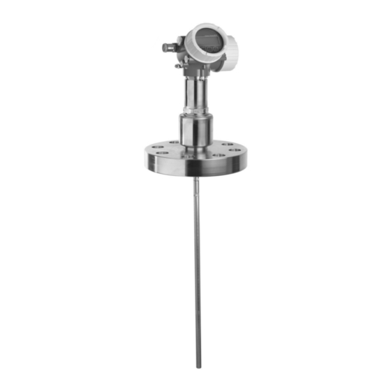
Levelflex FMP51, FMP52, FMP54 Product description Product description Compact device Levelflex A0014167 å 1 Design of the Levelflex Electronics housing Process connection (here as an example: flange) Rope probe End-of-probe weight Rod probe Coax probe Endress+Hauser... -
Page 8: Electronics Housing
Product description Levelflex FMP51, FMP52, FMP54 Electronics housing A0012422 å 2 Design of the electronics housing Electronics compartment cover Display module Main electronics module Cable glands (1 or 2, depending on instrument version) Nameplate I/O electronics module Terminals (pluggable spring terminals) -
Page 9: Incoming Acceptance And Product Identification
Levelflex FMP51, FMP52, FMP54 Incoming acceptance and product identification Incoming acceptance and product identification Incoming acceptance DELIVERY NOTE 1 = 2 A0013696 A0014041 A0013921 A0013922 A0013696 Made in Germany, 79689 Maulburg Levelflex IP68 / 66 NEMA 4X / 6P Order code:... -
Page 10: Product Identification
Incoming acceptance and product identification Levelflex FMP51, FMP52, FMP54 A0013696 A0014037 If one of the conditions does not comply, contact your Endress+Hauser distributor. Product identification The following options are available for identification of the measuring device: • Nameplate specifications • Order code with breakdown of the device features on the delivery note •... -
Page 11: Storage, Transport
Levelflex FMP51, FMP52, FMP54 Storage, Transport Only 33 digits of the extended order code can be indicated on the nameplate. If the extended order code exceeds 33 digits, the rest will not be shown. However, the complete extended order code can be viewed in the operating menu of the device (Diagnostics ®... - Page 12 Storage, Transport Levelflex FMP51, FMP52, FMP54 A0015471 Endress+Hauser...
-
Page 13: Mounting
Levelflex FMP51, FMP52, FMP54 Mounting Mounting Suitable mounting position A0012606 6.1.1 Mounting distances • Distance (A) between wall and rod or rope probe: – for smooth metallic walls: > 50 mm (2") – for plastic walls: > 300 mm (12") mm to metallic parts outside the vessel –... -
Page 14: Notes On The Process Connection
Mounting Levelflex FMP51, FMP52, FMP54 6.1.2 Additional conditions • When mounting in the open, a weather protection cover (1) may be installed to protect the device against extreme weather conditions. • In metallic vessels: Preferably do not mount the probe in the center of the vessel (2), as this would lead to increased interference echoes. - Page 15 Levelflex FMP51, FMP52, FMP54 Mounting Seal The thread as well as the type of seal comply to DIN 3852 Part 1, screwed plug form A. They can be sealed with the following types of sealing rings: • Thread G3/4": According to DIN 7603 with the dimensions 27 x 32 mm •...
- Page 16 Mounting Levelflex FMP51, FMP52, FMP54 Hight and diameter of the nozzle • Permissible nozzle diameter: £ 150 mm (6 in). For larger diameters the near range measuring capability may be reduced. For nozzles ³ DN300: (® ä 17). • Permissible nozzle height : £...
- Page 17 Levelflex FMP51, FMP52, FMP54 Mounting Installation in nozzles ³ DN300 If installation in ≥ 300mm/12" nozzles is unavoidable, installation must be carried out in accordance with the sketch on the right. A0014199 Lower edge of the nozzle Approx. flush with the lower edge of the nozzle (± 50 mm/2") Plate Pipe Æ...
-
Page 18: Securing The Probe
Mounting Levelflex FMP51, FMP52, FMP54 Securing the probe 6.3.1 Securing rope probes A0012609 Sag of the rope: ³ 1 cm per 1m of the probe length (0.12 inch per 1 ft of the probe length) Reliably grounded end of probe... - Page 19 Levelflex FMP51, FMP52, FMP54 Mounting 6.3.2 Securing rod probes • For Ex-approvals: For probe lengths ³ 3 m (10 ft) a support is required. • In general, rod probes must be supported if there is a horizontal flow (e.g. from an agitator) or in the case of strong vibrations.
- Page 20 Mounting Levelflex FMP51, FMP52, FMP54 ø a ø b ø<25 (1.0) 3 (0.12) » mm (in) A0012607 Probe rod, uncoated Sleeve bored tight to ensure electrical contact between the rod and sleeve! Short metal pipe, e.g. welded in place Probe rod, coated Plastic sleeve, e.g.
- Page 21 Levelflex FMP51, FMP52, FMP54 Mounting NOTICE Poor grounding of the end of probe may cause measuring errors. Apply a narrow sleeve which has good electrical contact to the probe. ► NOTICE Welding may damage the main electronics module. Before welding: Ground the probe and dismount electronics.
-
Page 22: Special Mounting Conditions
Center washer 3.1 Metallic center washer (316L) for level measurement 3.2 Non-metallic center washer (PEEK, PFA) for interface measurement For information on bypass solutions from Endress+Hauser please contact your Endress +Hauser sales representative. Feature 610 - Accessory mounted Center washer... - Page 23 Levelflex FMP51, FMP52, FMP54 Mounting Feature 610 - Accessory mounted Center washer Pipe Application Option Type of probe Æ d [mm (in)] Material Æ D [mm (in)] ³ 50 mm Interface measurement Rod probe 48...95 PEEK (1,89...3,74) (2") ³ 40 mm...
- Page 24 Mounting Levelflex FMP51, FMP52, FMP54 6.4.2 Non-metallic vessels A0012527 Non-metallic vessel Metal sheet or metal flange To measure, Levelflex with a rod probe needs a metallic surface at the process connection. Therefore: • Select an instrument version with metal flange (minimum size DN50/2").
- Page 25 Levelflex FMP51, FMP52, FMP54 Mounting 6.4.3 Plastic or glass tanks: Mounting the probe externally at the wall A0014150 Plastic or glass tank Metall sheet with threaded sleeve No free space between tank wall and probe! Requirements • The dielectric constant of the medium must be at least DC > 7.
-
Page 26: Mounting The Device
Mounting Levelflex FMP51, FMP52, FMP54 Mounting the device 6.5.1 Required mounting tools • For mounting thread 3/4": Hexagonal wrench 36 mm • For mounting thread 1-1/2": Hexagonal wrench 55 mm • To shorten rod or coax probes: Saw • To shorten rope probes: –... - Page 27 Levelflex FMP51, FMP52, FMP54 Mounting 4 / 6 mm 0.16 / 0.25 inch 5/15 Nm A0012453 1. Loosen the 3 Allen set screws using an Allen key AF3 (for 4mm ropes) or AF4 (for 6 mm ropes). Note: The set screws have got a clamping coating in order to prevent accidental loosening.
- Page 28 Mounting Levelflex FMP51, FMP52, FMP54 6.5.3 Mounting the device Mounting devices with thread A0012528 Devices with mounting thread are screwed into a welding boss or a flange and are usually also secured with these. • Tighten with the hexagonal nut only: –...
- Page 29 Levelflex FMP51, FMP52, FMP54 Mounting Mounting rope probes NOTICE Electrostatic discharges may damage the electronics. Earth the housing before lowering the rope into the vessel. ► A0012852 When lowering the rope probe into the vessel, observe the following: • Uncoil rope and lower it slowly and carefully into the vessel.
-
Page 30: Post-Installation Check
Mounting Levelflex FMP51, FMP52, FMP54 1. Unscrew the securing screw using an open-ended wrench. 2. Rotate the housing in the desired direction. 3. Firmly tighten the securing screw. (1,5 Nm for plastics housing; 2,5 Nm for aluminium or stainless steel housing). -
Page 31: Electrical Connection
Levelflex FMP51, FMP52, FMP54 Electrical connection Electrical connection Connection options 7.1.1 PROFIBUS PA A0011341 Terminals PROFIBUS PA Cable screen: Observe cable specifications (® ä 33) Cable entry Potential equalization Endress+Hauser... - Page 32 Electrical connection Levelflex FMP51, FMP52, FMP54 A0013759 Terminals switching output (Open collector) Cable entry Switching output Function Open collector switching output Switching behavior Binary (conductive or non-conductive), switches when the programmable switch point is reached Failure mode non-conductive Eectrical connection values U = 10.4 to 35 V...
-
Page 33: Connection Conditions
Levelflex FMP51, FMP52, FMP54 Electrical connection Switching output Signal source • Level linearized device variables • Distance • Terminal voltage • Electronic temperature • Relative echo amplitude • Interface linearized • Interface distance • Upper interface thickness • Relative interface amplitude... -
Page 34: Connection Data
• Integrated overvoltage protection (in preparation); Product structure: Feature 610 "Accessory mounted", option NA "Overvoltage protection". • External overvoltage protection, e.g. Endress+Hauser's HAW562 or HAW569. For detailed information please refer to the following documents: • HAW562: TI01012K • HAW569: TI01013K Connection data 7.3.1... - Page 35 Levelflex FMP51, FMP52, FMP54 Electrical connection Required tools and accessories: • For instruments with safety pin for the lid: AF 3 Allen key • Wire stripping pliers • When using stranded wires: Wire end sleeves. A0012619 1. Loosen the screw of the securing clamp of the connection compartment cover and turn the clamp 90°...
- Page 36 Electrical connection Levelflex FMP51, FMP52, FMP54 A0013837 Connect the cable in accordance with the terminal assignment . 8. When using screened cable: Connect the cable screen to the ground terminal. 9. Screw the cover onto the connection compartment. 10. For instruments with safety pin for the lid: Adjust the safety pin so that its edge is over the edge of the display lid.
-
Page 37: Post-Connection Check
Levelflex FMP51, FMP52, FMP54 Integration into a PROFIBUS network Post-connection check Are cables or the device undamaged (visual inspection)? Do the cables comply with the requirements? Do the cables have adequate strain relief? Are all cable glands installed, firmly tightened and correctly sealed? Does the supply voltage match the specifications on the transmitter nameplate? Is the terminal assignment correct (®... - Page 38 Integration into a PROFIBUS network Levelflex FMP51, FMP52, FMP54 8.2.1 Hardware adressing 1. Set switch 8 to "OFF". 2. Define the address with switches 1 to 7 according to the table below. The address change becomes effective after 10 seconds. The device restarts automatically.
-
Page 39: Commissioning
Levelflex FMP51, FMP52, FMP54 Commissioning Commissioning Display and operating module 9.1.1 Display appearance A0012635 å 10 Appearance of the display and operation module for on-site operation Measured value display (1 value max. size) 1.1 Header containing tag and error symbol (if an error is active) 1.2 Measured value symbols... - Page 40 Commissioning Levelflex FMP51, FMP52, FMP54 9.1.2 Navigation and selection from a list Use the operating keys to navigate within the operating menu and to select options from a list. Meaning "Minus" key Henceforth represented by S. • In a selection list: Moves the selection bar upward.
-
Page 41: Operating Concept
Levelflex FMP51, FMP52, FMP54 Commissioning Operating concept 9.2.1 Structure Language Display/operation Parameter 1 Parameter 2 Parameter N Setup Setup parameter 1 Setup parameter 2 Setup parameter N Enter access code Advanced setup Parameter 1 Parameter N Submenu 1 Submenu N... - Page 42 Commissioning Levelflex FMP51, FMP52, FMP54 9.2.2 Submenus and user roles The submenus are designed for different user roles. A user role is defined by typical tasks within the lifecycle of the device. User role Typical tasks Submenu Operator Tasks in the ongoing process: "Language"...
-
Page 43: Adjust The Display Contrast
Levelflex FMP51, FMP52, FMP54 Commissioning Adjust the display contrast • O + F (pressed simultaneously): increases the contrast. • S + F (pressed simultaneously): decreases the contrast. Unlock the device If the device has been locked, it must be unlocked before the measurement can be configured. - Page 44 Commissioning Levelflex FMP51, FMP52, FMP54 1. Unscrew the lid from the compartment for the display and operating module. 2. Slightly turn the display and operating module to remove it from the compartment. 3. Set the locking switch (WP: Write Protection) into the desired position. (A): unlocked; (B): locked.
-
Page 45: Set The Operating Language
Levelflex FMP51, FMP52, FMP54 Commissioning Set the operating language A0013637 Endress+Hauser... -
Page 46: Configuration Of A Level Measurement
Commissioning Levelflex FMP51, FMP52, FMP54 Configuration of a level measurement 100% A0011360 å 14 Configuration parameters for level measurements in liquids LN = Length of probe R = Reference point of the measurement D = Distance E = Empty calibration (= Zero point) -
Page 47: Configuration Of An Interface Measurement
Levelflex FMP51, FMP52, FMP54 Commissioning Step Parameter Action Setup ® Signal quality Displays the signal quality of the level echo. Setup ® Mapping ® Confirm distance Compare the displayed distance to the real distance in order to start the recording of the mapping curve. -
Page 48: User-Specific Applications (Operation)
Commissioning Levelflex FMP51, FMP52, FMP54 Step Parameter Action Setup ® Distance unit Select distance unit. Setup ® Operating mode Select "Interface". Setup ® Tank type Select tank type. Setup ® Tube diameter Enter the diameter of the bypass or stilling well. - Page 52 *71113567* KA01079F/00/EN/10.10 71113567 71113567 CCS/COSIMA...
Need help?
Do you have a question about the Levelflex FMP51 and is the answer not in the manual?
Questions and answers