Endress+Hauser HART Levelflex FMP51 Brief Operating Instructions
Guided level-radar
Hide thumbs
Also See for HART Levelflex FMP51:
- Operating instructions manual (254 pages) ,
- Technical information (132 pages) ,
- Brief operating instructions (56 pages)
Table of Contents
Advertisement
Quick Links
Brief Operating Instructions
Levelflex FMP51, FMP52, FMP54
Guided Level-Radar
These Instructions are Brief Operating Instructions; they do not replace the
Operating Instructions included in the scope of supply.
For detailed information, refer to the Operating Instructions and other
documentation on the CD-ROM provided or visit "www.endress.com/
deviceviewer".
KA01077F/00/EN/05.10
71113565
Advertisement
Table of Contents

Related Manuals for Endress+Hauser HART Levelflex FMP51


Summary of Contents for Endress+Hauser HART Levelflex FMP51
- Page 1 Brief Operating Instructions Levelflex FMP51, FMP52, FMP54 Guided Level-Radar These Instructions are Brief Operating Instructions; they do not replace the Operating Instructions included in the scope of supply. For detailed information, refer to the Operating Instructions and other documentation on the CD-ROM provided or visit "www.endress.com/ deviceviewer".
-
Page 2: Table Of Contents
8.8 User-specific applications (operation) ........47 Endress+Hauser... -
Page 3: Important Document Information
A connection that has to be connected to the plant grounding system: This may be a potential equalization line or a star grounding system depending on national or company codes of practice. A0011201 1.1.3 Tool symbols A0011222 A0011220 A0011219 A0013442 A0011221 Phillips head Flat blade Torx screwdriver Allen key Hexagon wrench screwdriver screwdriver Endress+Hauser... - Page 4 Ã 1.1.5 Symbols and notation in graphics Symbol Meaning 1,2,3 ... Item numbers A, B, C, ... Views A-A, B-B, C-C, ... Sections Hazardous area Indicates a hazardous area. A0011187 Safe area (non-hazardous area) Indicates a non-hazardous location. A0011188 Endress+Hauser...
-
Page 5: Basic Safety Instructions
The manufacturer is not liable for damage resulting from incorrect or non-designated use. Borderline cases: For special measuring materials and cleaning agents: Endress+Hauser will assist with ► identifying the corrosion resistance of wetted parts but does not accept any warranty or liabilty. -
Page 6: Occupational Safety
► Constructional changes at the device Unauthorized changes of the mechanical construction of the device are prohibited and may result in unforeseeable risks: If constructional changes are required: Contact Endress+Hauser. ► Repairs In order to ensure operational safety: Only perform repairs to the device if they are expressly allowed. -
Page 7: Product Description
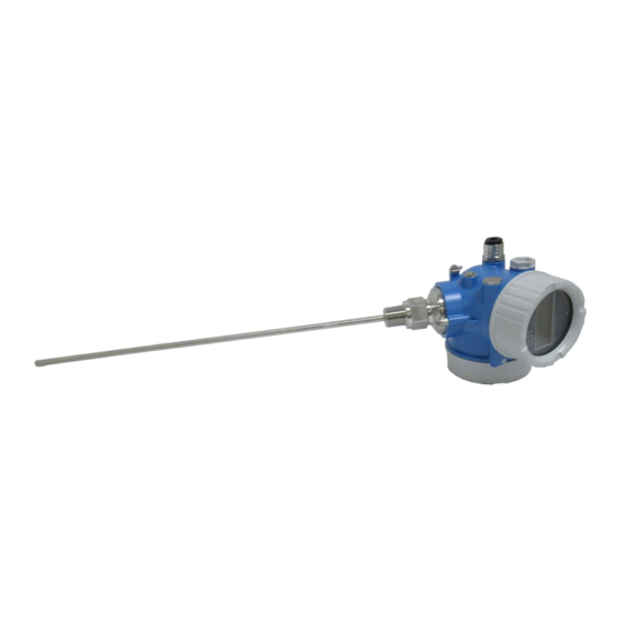
Levelflex FMP51, FMP52, FMP54 Product description Product description Compact device Levelflex A0014167 å 1 Design of the Levelflex Electronics housing Process connection (here as an example: flange) Rope probe End of probe weight Rod probe Coax probe Endress+Hauser... -
Page 8: Electronics Housing
Electronics housing A0012422 å 2 Design of the electronics housing Electronics compartment cover Display module Main electronics module Cable glands (1 or 2, depending on instrument version) Nameplate I/O electronics module Terminals (pluggable spring terminals) Connection compartment cover Grounding terminal Endress+Hauser... -
Page 9: Incoming Acceptance And Product Identification
- see instructions Ta: -40...+80 °C Ta > 60 °C: Mat.: Graphite, Al203, 316L,316,Alloy C22 Z-65.16-354 FISCO Ex d DeviceID: 452B481005-A91234010AB XA500F-- ex works FW: 01.00.00 Dev.Rev.: 1 Ex i if modification see sep. label Date: 2010-03 250002796-A A0013696 A0014038 Endress+Hauser... -
Page 10: Product Identification
Incoming acceptance and product identification Levelflex FMP51, FMP52, FMP54 A0013696 A0014037 If one of the conditions does not comply, contact your Endress+Hauser distributor. Product identification The following options are available for identification of the measuring device: • Nameplate specifications • Order code with breakdown of the device features on the delivery note •... -
Page 11: Storage, Transport
Risk of injury if the hosuing breaks away! Transport the measuring device to the measuring point in its original packaging or at the ► process connection. Comply with the safety instructions, transport conditions for devices over 18kg (39.6lbs). ► A0013920 Endress+Hauser... -
Page 12: Mounting
– for concrete walls: > 500 mm (20") , otherwise the available measuring range may be reduced. • Distance (B) between rod or rope probe and internal fittings in the vessel: > 300 mm (12") • Distance (C) from end of probe to bottom of the vessel: > 10 mm (0.4"). Endress+Hauser... - Page 13 • When installing in tanks with a lot of internals or internals situated close to the probe: use a coax probe. 6.1.4 Wall and pipe mounting Endress+Hauser offers a mounting bracket for installing the device on pipes or on walls. Ordering information: Feature 600 "Probe Design", Option MB "Sensor remote, 3m/9ft cable" . Endress+Hauser...
-
Page 14: Additional Mounting Hints
The easiest way to fix the rope probes is to screw them to the internal thread on the lower end of the weight (® ä 19). • The ideal installation is mounting in a screwed joint / screw-in sleeve which is internally flush with the container ceiling. • Alternative: nozzle mounting Endress+Hauser... - Page 15 FMP51 and FMP52. Probe Max. nozzle height (= length of the center rod) Option to be selected in feature 060 "Probe") FMP51 150 mm 6 inch 300 mm 12 inch FMP52 150 mm 6 inch 300 mm 12 inch Endress+Hauser...
- Page 16 Securing rod probes • Rod probes must be supported if there is a horizontal flow (e.g. from an agitator) or in the case of strong vibrations. • Rod probes may only be supported at the end of the probe. Endress+Hauser...
- Page 17 Short metal pipe, e.g. welded in place Æ probe Æ a [mm (inch)] Æ b [mm (inch)] 8 mm (1/3") < 14 (0.55) 8.5 (0.34) 12 mm (1/2") < 20 (0.78) 12.5 (0.52) 16 mm (0.63in) < 26 (1.02) 16.5 (0.65) Endress+Hauser...
- Page 18 Apply a narrow sleeve which has good electrical contact to the probe. ► NOTICE Welding may damage the electronics. Before welding: Ground the probe and dismount electronics. ► 6.2.3 Securing coax probes A0012608 Coax probes can be supported at any point of the outer tube. Endress+Hauser...
- Page 19 Make the rope longer than the required measuring range such that there is a sag in the middle of the rope that is ≥ 1cm/(1 m rope length) [0.12 inch/(1 ft rope length)]. Tensile load limit of rope probes: Endress+Hauser...
- Page 20 (see feature 610 of the product structure). Note: For interface measurements only use the nonmetallic center washers made of PEEK or PFA (feature 610, options OD or OE). • Coax probes can always be applied if there is enough mounting space. Endress+Hauser...
- Page 21 • Select an instrument version with metal flange (minimum size DN50/2"). • Or: mount a metal sheet with a diameter of at least 200 mm (8") to the probe at the process connection. Its orientation must be perpendicular to the probe. No additional measures are required for coax probes. Endress+Hauser...
- Page 22 • If the tank diameter exceeds 300 mm (12"): A metal sheet with a diameter of at least 200 mm (8") must be mounted to the probe at the process connection. Its orientation must be perpendicular to the probe (see above). Endress+Hauser...
-
Page 23: Mounting The Device
Rod probes of FMP52 can not be shortened as they are coated. Shortening rope probes Rope probes must be shortened if the distance to the container floor or outlet cone is less than 10 mm (0.4 in). Rope probes of FMP52 can not be shortened as they are coated. Endress+Hauser... - Page 24 The centerings are held with borders on the rod. Shortening is possible up to approx. 10 mm (0.4 in) below the centering unit. The coax probe is shortened by sawing the pipe at the bottom end. Endress+Hauser...
- Page 25 • When installing in metal silos, take care to ensure good metallic contact between the process connection and silo. Flange mounting For devices with mounting flange: If a seal is used, be sure to use unpainted metal bolts to ensure good electrical contact between probe flange and process flange. Endress+Hauser...
- Page 26 • Do not kink the rope. • Avoid any backlash, since this might damage the probe or the vessel fittings. 6.3.4 Turning the transmitter housing To provide easier access to the connection compartment or display module, the transmitter housing can be turned: Endress+Hauser...
- Page 27 Optional: pull out the display module with a gentle rotation movement. Rotate the display module into the desired position: Max. 8 ´ 45 ° in each direction. Without display module pulled out: Allow display module to engage at desired position. Endress+Hauser...
-
Page 28: Post-Installation Check
• Process pressure (refer to the chapter on "Material load curves" of the "Technical Information" document) • Ambient temperature range • Measuring range Are the measuring point identification and labeling correct (visual inspection)? Is the device adequately protected from precipitation and direct sunlight? Are the securing screw and securing clamp tightened securely? Endress+Hauser... -
Page 29: Electrical Connection
Active barrier with power supply (e.g. RN221N): Observe terminal voltage (® ä 33) HART communication resistor (³250 W): Observe maximum load (® ä 33) Connection for Field Communicator 375/475 or Commubox FXA195 Analog display device: Observe maximum load (® ä 33) Observe cable specification (® ä 32) Potential equalization Cable entry Endress+Hauser... - Page 30 Supply voltage for current output 2 (e.g. RN221N); Obesrve terminal voltage (® ä 33) Analog display device ; observe maximum load Terminal for the potential equalization line This version is also suited for single-channel operation. In this case, current output 1 must be used. Endress+Hauser...
- Page 31 (9)transmitter ground terminal before connecting up the device. In order to ensure electromagnetic compatibility (EMC): Do not ground the device via the protective earth conductor of the supply cable. Instead, ground the device via the process connection (flange or threaded connection) or the external ground terminal. Endress+Hauser...
-
Page 32: Connection Conditions
• Integrated overvoltage protection (in preparation); Product structure: Feature 610 "Accessory mounted", option NA "Overvoltage protection". • External overvoltage protection, e.g. Endress+Hauser's HAW562Z. When using the external overvoltage protection HAW562Z in explosion hazardous areas observe the associated Safety Instructions XA015R. -
Page 33: Connection Data
Feature 020 of the product structure 7.3.3 Maximum load In order to ensure a suffiecient terminal voltage at the device, the load resistance R (including wire resistance) must not exceed a value depending on the voltage U supplied by the supply unit., Endress+Hauser... - Page 34 Feature 010 - Approval 13.5 to 30 V Ex d / XP, Ex ic(ia), Ex tD / DIP Feature 20 "Power Supply, Output", Option C "2-wire; 4-20mA HART, 4-20mA" Outputs Terminal voltage Feature 010 "Approval" 13.5 to 30 V Endress+Hauser...
-
Page 35: Connecting The Measuring Device
Before switching on the supply voltage: Connect the potential bonding line to the exterior ► ground terminal. Required tools and accessories: • For instruments with safety pin for the lid: M3 Allen key • Wire stripping pliers • When using stranded wires: Wire end sleeves. Endress+Hauser... - Page 36 Strip the cable ends 10 mm (0.4 in). For stranded cables, also attach wire end ferrules. Firmly tighten the cable glands. A0013837 Connect the cable in accordance with the terminal assignment . When using screened cable: Connect the cable screen to the ground terminal. Screw the cover onto the connection compartment. Endress+Hauser...
-
Page 37: Post-Connection Check
Is the terminal assignment correct ? If supply voltage is present, is the device ready for operation and do values appear on the display module? Are all housing covers installed and firmly tightened? Is the securing clamp tightened correctly? Endress+Hauser... -
Page 38: Commissioning
Representation of a parameter (here: a parameter with selection list) 3.1 Header containing parameter name and error symbol (if an error is active) 3.2 Selection list; Â marks the current parameter value. Input matrix for numbers Input matrix for alphanumeric and special characters Endress+Hauser... - Page 39 • Confirms a changed parameter value. A0011973 "Escape" key combination (press keys simultaneously) Henceforth represented by S + O. • Closes a parameter without accepting the changes. • Quits the current menu layer and returns to the next higher layer. A0012661 Endress+Hauser...
-
Page 40: Operation Concept
Parameter 1 Parameter N Submenu 1 Submenu N Parameter 1 Diagnostics Parameter N Submenu 1 Submenu N Direct access Expert System Sensor Output Communication Application Diagnostics A0012647 å 5 Basic structure of the operating menu; gray: submenus; white: parameters Endress+Hauser... - Page 41 Expert Tasks which require detailed knowledge about the "Expert" instrument: • Commissioning of measurements under demanding conditions. • Optimization of the measurement under demanding conditions. • Detailed configuration of the communication interface. • Error diagnosis in diffcult cases. Endress+Hauser...
-
Page 42: Adjust The Display Contrast
In order to unlock the device, shift the locking switch (which is located below the display module) into the "unlocked" position. WP SIM DISPL Spare part: FMP52X-AB 02.01.03 Dev_R ex works SW update #1 SW update #2 A0013132 Endress+Hauser... - Page 43 Setup ® Advanced setup ® Enter access code To unlock the device: Enter the previously defined access code. Setup ® Advanced setup ® Enter access code To lock the device again: Enter a number other than the previously defined access code. Endress+Hauser...
-
Page 44: Set The Operating Language
Commissioning Levelflex FMP51, FMP52, FMP54 Set the operating language A0013637 Endress+Hauser... -
Page 45: Configuration Of A Level Measurement
Setup ® Full calibration Enter distance F between the minimum (0%) and maximum (100%) level. Setup ® Level Displays the measured level L. Setup ® Distance Displays the distance D between the reference point R and the level L. Endress+Hauser... -
Page 46: Configuration Of An Interface Measurement
= Distance of interface (Distance from reference point to lower medium) F = Full calibration (= span) = Interface level LN = Length of probe = Distance from reference point R to total level UB = Upper blocking distance = total level UP = Thickness of upper medium Endress+Hauser... -
Page 47: User-Specific Applications (Operation)
"Tank type" = "Bypass/pipe" User-specific applications (operation) For details of setting the parameters of user-specific applications, see separate documentation: • Operator ® BA01000F/00/EN (Operating Instructions) • Maintenance ® BA01000F/00/EN (Operating Instructions) • Experte ® GP01000F/00/EN (Description of Device Parameters) Endress+Hauser... - Page 48 *71113565* KA01077F/00/EN/05.10 71113565 71113565 CCS/COSIMA...
Need help?
Do you have a question about the HART Levelflex FMP51 and is the answer not in the manual?
Questions and answers