
Related Manuals for Alphatech IP-VarioBell


Summary of Contents for Alphatech IP-VarioBell
- Page 1 IP-VarioBell - DoorPhone vrátný IP-VarioBell IPVB-00, IPVB-01, IPVB-02 IPVB-00C, IPVB-01C, IPVB-02C VBD5-mod, VBD10-mod, VBDKey Installation and operating instructions...
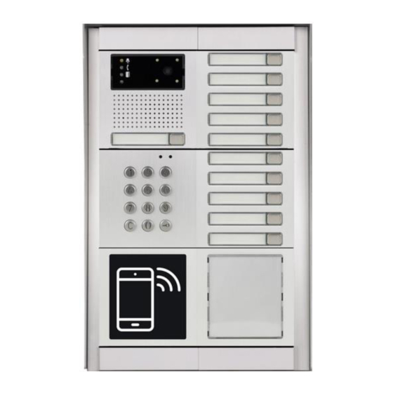
- Page 3 To each call button you can assign up to 5 phone numbers with possibility of progressive or simoultaneous dialling. The IP-VarioBell doorphone is supplied with one or two call buttons or no call buttons, in audio version or with a color camera module. The system is modular and can be expanded up to 87 call buttons and equipped with an access control and dialling keypad and NFC proximity door access controller.
-
Page 4: Table Of Contents
Tlačítkové Moduly ......... Chyba! Záložka není definována. 1.3.1 Mechanické díly ..................11 1.3.2 ŘIPOJENÍ IP-V ................14 ARIO IP-VarioBell základní deska ..............14 1.4.1 Napájecí zdroj - svorka (10) ..............18 1.4.2 Sběrnice pro rozšíření tlačítek ..............18 1.4.3 ŘIPOJENÍ ROZŠIŘUJÍCÍCH MODULŮ ÁLOŽKA NENÍ... - Page 5 ..................41 URRENT STATUS 4.2.1 Language settings ................... 42 .................. 42 NETWORK SETTING 4.3.1 IP Network setting .................. 42 4.3.2 SIP setting ....................45 4.3.3 WEB server ..................... 49 ..................... 51 ASIC SETTING 4.4.1 Phone book ..................... 51 4.4.2 Relays ...................... 54 4.4.3 Door sensors ...................
-
Page 6: Basic Description
1 Basic description Features ▪ audio is full duplex with ECHO cancellation ▪ phone book with up to 999 subscribers/users with 5 phone numbers for each user (max. 87 physical call buttons + keyboard + NFC access module) ▪ every subscriber can use more phone numbers with progressive or simultaneous calling ▪... -
Page 7: Used Terminology
Used terminology • Incoming call - Connection between the doorphone and a phone made by selecting an option on the phone. The doorphone connects the call after set number of rings. • Outgoing call - Connection between the doorphone and a phone made by choosing an option on the doorphone (e.g., pressing a call button). - Page 8 • Dynamic Host Configuration Protocol (DHCP) is an application protocol from the TCP / IP family. It is used to automatically assign IP addresses to individual personal computers in computer networks, thus simplifying their management • Internet is a worldwide system of interconnected computer networks •...
-
Page 9: Sestava Modulů
/ dialling keypad and an NFC proximity door access controller. The basic module IPVB-xx. The IP-VarioBell basic module is can be equipped with two call buttons / one double call button (IPVB-02), one single call button (IPVB-01) or zero call buttons (IPVB-00). - Page 10 1.3.1 Call button modules Basic module Basic module Basic module IPVB-02 IPVB-01 IPVB-00 Basic module Basic module Basic module IPVB-02C IPVB-01C IPVB-00C Call buttons module Call buttons module Keypad module VBD5-mod VBD10-mod VBDKey IP VarioBell - installation and operating instructions...
-
Page 11: Tlačítkové Moduly
1.3.2 Mechanical parts For simplicity, the mechanical parts for 1, 2 and 3 modules are shown here. There is a maximum of 3 modules in one column, a large set contains a maximum of 2 columns (6 modules). For even larger assemblies, blocks of 6 modules can be stacked on top of or next to each other. - Page 12 Mounting and cover frame – for surface and flush mounting for 1 module for 2 modules for 3 modules IP VarioBell - installation and operating instructions...
- Page 13 Rain hoods – for flush mounting - examples Rain hood-1 Rain hood-2 Rain hood- 2x2 Surface mounting boxes with integrated rain hoods – examples for surface mounting (frames are supplied separately) SMB-1 SMB-2 SMB-3 IP VarioBell - installation and operating instructions...
-
Page 14: Připojení Ip-Vario Bell
(relays). 1.4.1 IP-VarioBell motherboard The motherboard is the same for all IP-VarioBell models and only differs in the installation of the camera module. As standard, it is equipped with a PoE module (according to the IEEE802.3af standard), a connector for connecting expansion modules, LED name-card backlight, a microSD card reader and two relay switches. - Page 15 11. Input for power supply IP-VarioBell 12V AC / DC (consumption approx. 300mA max.). It is recommended to use a direct current (DC) power supply. 12. Output 12V DC, max. 300mA, e.g. for power supply of low consumption electric lock with PoE power supply of the IP-VarioBell.
- Page 16 IP VarioBell - installation and operating instructions...
- Page 17 13. The yellow LED lights up when the doorphone is ringing or establishing and terminating a connection (establishing connection). 14. The blue LED lights up when the connection is established and you can talk (Call). 15. The green LED lights up when at least one of the two relay switches is active (Door open).
-
Page 18: Napájecí Zdroj - Svorka (10)
17. White LED to illuminate the area in front of the camera (only for models with a camera) 18. Camera lens (camera models only). The lens view angle is 120°, max. resolution 640x480px. 19. Speaker 20. Microphone 21. White LED – name-card illumination 22. -
Page 19: Kabel K0 / K1
The VBDx-mod electronics board is only connected to the VarioBell call buttons module via a terminal block (E5) and a three-core connection cable (E4). The connector (E7) is not used with the IP-VarioBell version. The connection is made using the flat cable K1 (two black connectors at both ends). -
Page 20: Příklad Propojení Modulů Vbd10-Mod
If the K1 cables were connected randomly, nothing happens and the numbering is retained (given by the DIP switch on the relevant module). Fig. 2 Interconnection of IP-VarioBell and VBD10-mod modules IP VarioBell - installation and operating instructions... -
Page 21: Příklad Propojení Modulů Vbd5-Mod
If the K1 cables were connected randomly, nothing happens and the numbering is retained (given by the DIP switch on the relevant module). Fig. 3 Interconnection of IP-VarioBell and VBD10-mod modules IP VarioBell - installation and operating instructions... -
Page 22: Číslování Tlačítek
1.5.4 Call buttons numbering The numbering of the buttons depends on the setting of the DIP switch on each call buttons module. The numbering does not depend on the way (order) of interconnection of individual call buttons modules. DIP switch setting (E6) on the call button module. - Page 23 IP VarioBell - installation and operating instructions...
- Page 24 The numbering of the modules is shown in the figure above, in the left part there are modules with 5 call buttons VBD5-mod and in the right part there are modules with 10 call buttons VBD10-mod (5 double call buttons). The call buttons module with the required numbering can be found in the figure above.
-
Page 25: Připojení Klávesnice Vbdkey
(E2) tlačítkového modulu. této Konektor (E7) verze IP-VarioBell nepoužívá. Volba se zadává postupným zmačknutím tlačítek s číslicemi, pro zadání hesla se jako první musí zmačknout symbol klíče , pro zavěšení se kdykoli zmačkne a vrátný zavěsí, nebo zruší proces zadávání čísel (Cancel). -
Page 26: Signalizace Na Předním Panelu Základního Modulu
Pokud do systému připojíte dvě klávesnice, tak budou obě funkční a budou mít stejnou funkci. 1.7 Signalizace na předním panelu základního modulu Mechanika IP-VarioBell umožňuje v okénku základního modulu signalizovat stav vrátného. Toho se zpravidla využívá pro neslyšící návštěvníky. •... -
Page 27: Instalace
2 Instalace 2.1 Montáž IP VarioBell - installation and operating instructions... - Page 28 Postup montáže: A. Příprava montážního otvoru ve zdi – doporučená výška je kolem 160cm od země. Rozměr otvoru záleží na počtu modulů a zde jsou orientačně uvedeny rozměry pro 1, 2 a 3 moduly (základní montážní krabice). Pro větší sestavy se celek skládá z těchto montážních krabic řazením vedle sebe a pod sebou.
- Page 29 Umístění IP-VarioBell na zdi IP VarioBell - installation and operating instructions...
-
Page 30: Zapojení Spínačů
(režim spínače 1 a 2 je monostabilní) toto schéma platí i postupné otevírání dveří. Toto zapojení je nejčastější, jeden společný zdroj napájí vrátný IP-VarioBell a oba elektrické zámky. Proudové zatížení zdroje záleží zvláště na použitých elektrických zámcích. Standardní zámek má... - Page 31 IP VarioBell - installation and operating instructions...
-
Page 32: Poe Napájení
2.2.1 PoE napájení IP-VarioBell je vybaven obvodem pro napájení po UTP kabelu – PoE. Pokud máte síťový switch vybaven napájením PoE, nebo vlastníte napáječ PoE (krabička velikosti síťového adaptéru vložená do přívodu UTP kabelu - podle normy IEEE802.3af), tak již pro funkci vrátného nepotřebujete napájení... -
Page 33: Kódové Relé (Cosw)
= sepnuto). Vstupy pro dveřní snímače lze využít také jako odchodové tlačítka. V nastavení IP-VarioBell lze vybrat, který spínač tento vstup ovládá. Prakticky ke vstupu se připojí tlačítko NO a při stisknutí sepne spínač v monostabilním režimu na dobu sepnutí spínače. -
Page 34: Mikro Sd Karta
2.2.4 Mikro SD karta Karta mikroSD slouží k uložení uživatelských zvukových souborů a v budoucnu bude možnost ukládání fotografií, videa, audia na MikroSD kartu jako záznamník. Pokud zvolíte uživatelský tón a karta mikroSD nebude zasunuta ve vrátném, tak se použijí tóny základní signalizace. SD kartu nikdy nevysunujte během zapnutého vrátného! IP VarioBell - installation and operating instructions... -
Page 35: Service Of Ip Variobell
3 Service of IP VarioBell Signalling overview The door entry IP VarioBell signalling acustically stages which occurs during operation. Further signalling is by 2 colour LED (placed right under black plexi). Acustical signalling for each status mentioned in bellow table might be switched off or might be used default tones “beeping”... -
Page 36: Button Press - Code Lock
1. Phone book position for selected button must be permitted 2. Must be fill min. 1 from 5 phone numbers (or IP adresses in P2P mode) 3. At filled phone number is active time plan in appropriate time or no plan is selected. -
Page 37: Visitor Inside Building
Visitor inside building By person inside building is person who is in communication with door entry IP VarioBell. 3.3.1 Outgoing call Outgoing call is call from door entry (start by visitor). After door entry dial is ringit phone inside the building. When call is picked up you can talk to visitor at door and by code dialling you can activate relay. -
Page 38: Video
Video At models with camera is possible received video as follow: - IP phone with LCD display - PC – WEB browser - PC with programm UDVguard (www.alphatechtechnologies.cz) - PC with general programm for video watching (for example VLC) - Android device (smart phone, tablet) UDVguard (Google Play) - Apple device (smart phone, tablet) UDVguard (iTunes) Video formats: JPG, MJPG, H.263, H.264 Video for WEB:... -
Page 39: Parametres Programming
4 Parametres programming Parametres programming is performed by ordinary WEB browser. (Caution! version of IE V7 and lower are not supported). WEB interface access For successful display of WEB interface of IP VarioBell door entry we go through some details. Field length - names, titles, codes, passwords have fix length 40 characters. -
Page 40: Login
2. Generally in PC setup you program temporarily own IP address.In PC door entry segment for example 192.168.1.10. After change of door entry IP address you have return setting in PC back. Then you can setup parameters of door entry including IP address and after restart of IP VarioBell door entry you can login to door entry WEB page on new IP adress. -
Page 41: Current Status
You enter now to first petting page of door entry IP VarioBell. On this page is display „Current status“. All necessary data about door entry status are here. Current status Current status display basic data about IP VarioBell door entry status. It displays Firmware version,door entry model, options connection (camera), SD card, MAC adresses, current time, network setting, door entry mode (P2P or SIP server), registration status and small calls statistic. -
Page 42: Language Settings
4.2.1 Language settings After language selection please don’t forget click on „Save changes“. On the right top corner is display flag of current used language in whole WEB interface. After click on flag accessible language will be displayed. After language selection please don’t forget click on „Save changes“ otherwise language selection wont be performed. - Page 43 After performing of required changes please don’t forget click on „Save and restart“. Setup via DHCP - ON / OFF using DHCP assignment of IP adresses IP adress, Network mask – IP adress setting, mask. In case of emergency please contact your network administrator Network gateway –...
- Page 44 DHCP configuration: After performing of required changes please don’t forget click on „Save and restart“. DHCP – by mark of this checkbox as same as saving and restart will be assigned to door entry IP VarioBell - IP adress by DHCP. NAT policy - there is the choice of what kind of translate IP addresses used NAT address - used for network traffic through the router (modifies transcription of the original or destination IP address)
-
Page 45: Sip Setting
4.3.2 SIP setting The door entry IP VarioBell might operates in 2 basic SIP modes. It is either SIP server – door entry registration is performed to SIP server and then you call to phone numbers assigned by SIP server or Peer to Peer (P2P) – door entry call exact IP adress and SIP server services can´t be used. - Page 46 Account - unit name in SIP protocol (usually line number or name without diacritics) Auth.ID - name for SIP server registration Password - password for SIP server registration Send register – when registration is necessary (mostly yes) then this parametr must be used Registration server - IP adress or server name of registration server (in most systems and installations is enough to insert IP adress).
- Page 47 Peer to Peer mode (P2P) After performing of changes please don’t forget click on „Save changes“. Display name – name by which is device presented in network (for example will display as door entry name in programms UDV panel, UDVguard) SIP User Agent –...
- Page 48 INVITE regest sends to outbound proxy adress. Outbound proxy is used due NAT. When is not used dont fill up. Port - SIP port is usually 5060 or 5061 SIP Transport - TCP or UDP, or automatic selection Provisional code - determine if during ringing will be sends SIP code „180 Ringing“...
-
Page 49: Web Server
4.3.3 WEB server After performing of changes please don’t forget click on „Save and restart“. WEB interface TCP port - posibility of chase usuall TCP port 80 to other (security reasons) Service password / Retype password – inserting of new access password (instead default password 1234) –... - Page 50 Video password – inserting of new video access password (instead default password 1234) – length max.40 characters (name for video access is video) Enable telnet – available only for special customization. posibility ON / OFF access from telnet (name: root, pass: 8765). telnet is not recommended, in practice, this possibility has caused a lot of problems.
-
Page 51: Basic Setting
Basic setting In this part are setup user and most often changed parametres. 4.4.1 Phone book After performing of changes please don’t forget click on „Save“. The phone book contents 999 subscribers. For first 99 subscribers agree subscriber number with button number. In this version of door entry – IP VarioBell is max = 87 button. - Page 52 Every position of phone book allows insert up to 5 phone numbers with possibility to join some of them (or all) into group and call group of phone numbers simultaneously. Title – This text has informative character only. In case of display using will be name shown in list selection.
- Page 53 according buttons 1 – 2 in this model). Each subscriber has one cod efor every relay. Calling – description The group means that 2 or more phone numbers creates group and those Numbers are dialled simultaneously (all are ringing together). Who from dialled Subscribers pick up first can talk and ringing to other subscribers in group Will be ended.
-
Page 54: Relays
4.4.2 Relays After performing of changes please don’t forget click on „Save“. In relays setting are accessible 4 relays. The relays 1 and 2 is output of relays contacts directly in IP VarioBell door entry. Next 2 relays (3 and 4) is possible use for remote relays (IP relays via follow) or as virtual relay usefull for synchronization to allows creation of more difficult functions of relays. - Page 55 with all codes to original function. When such status repeats regularly (for example school) you can use time plan. Time table – defines time period when relay is working and hen not. For example is shop operation time , school, etc.. Relay mode - monostable –...
- Page 56 By synchronization you can create different closing combination. Synchronize delay – time between synchronization start and its evaluation. Usage for example in more relays closing combination for one code Active on call – options are none (calling has no influence for relay status) incoming call –...
- Page 57 E.g. http://192.168.1.250/relay_control?1=off - switches off relay 1 (doorphone to the default IP address). Releasing the relay is important in the bistable switch mode. Security output code – relay output is close/open in default. This static status is dangerous in case of unauthorised enter for example by door entry demaged and short circuit wires of power supply and electrical lock.
- Page 58 Practical examples of switch settings: 1. Locking the door lock: Phone code: 55 Button code: 121 Schedule - time table 1 = work: Locking time: 5sec (run time) a) Codes are active all the time b) The code from the buttons is limited by the "work"...
- Page 59 then you must not forget to dial code 10 when you actually leave. These codes are of course selected from your phone, in conjunction with the door Communicator 2. Switch 1 switches 2 pulses per command: Set the same code as in the previous example.
- Page 60 5. The switch switches according to the time schedule (closed for a certain period of time by the weekly timetable "work = time table 1") Note: The relay is closed at set intervals, outside of these intervals relay is open. E.g. on Monday from 8:00 to 15:00 is relay closed. 1.
-
Page 61: Door Sensors
4.4.3 Door sensors Door sensors are special functions of door entry IP VarioBell which is optional. It is HW option which is different according button number of each model – inputs for door sensors. There is created information in the system about close/open the door. -
Page 62: Setting Snmp
Input door sensor 1 / 2 Exit button – relay 1-4 – because the use of door sensors not found so wide usage, so these can be used as two inputs to the function Exit button. When the input connections (short) so activates the corresponding relay (switch monostabil) . -
Page 63: Time Profiles
Variables in MIB tree – is designed for identification of none sense numeral chain OID OID is numeral identificator which definitely identify every value in SNMP communication. OID is created by number sequence separand by dot. Every dot represent exact level of tree structure into which are OID maped. -
Page 64: Date And Time Setting
possible deactivate whole day (first item on the row select „Active“ – Yes /No) . In example on the picture it is Saturday or whole day setup on active – in example i tis sunday. To use correctly this feature is necessary to setup correct time in the unit (via Date and time setting) Code for activation / deactivation–... - Page 65 Network time server – IP adress or domain name of NTP server. When you dont know then by inserted * will IP VarioBell find NTP server automatically according own selection. Condition is setup in network setting start gate and DNS. Daylight saving time –...
-
Page 66: E-Mail
4.4.7 E-mail When you want inform subscriber about missed calls from door entry you can setup IP VarioBell to sent out email after every missed call. You can setup own subject and text of email. When you have door entry with camera you can automatically add to email one or more pictures from camera. - Page 67 SMTP port – adjust in case of none standard SMTP server setting only. SMTP port is setup usually on value 25, but better is use port 587. SMTP, there are three systems: Port 25 not allow encrypted - it is marked as obsolete, insufficient safety Port 465, not a domain hosting - is labeled as not recommended at Port 587, has no maladies previous two, is currently the only...
-
Page 68: Extended Setting
Extended setting This part is designed for system setting which are done once during installation or when are problems with device kompatibility. 4.5.1 DoorPhone After performing of changes please don’t forget click on „Save“. Ringing timeout – time for which is ringing. When is setup more numbers as same as progressive ringing then after this time ringing is ended on first phone number (IP adress in P2P) and starts ringing on second. - Page 69 usually 2-5min (according SIP device setting). You can record message to SD card during this time and simultaneously send email. Maximum call duration – when call is picked up timer for call duration limit is activated. When you insert empty, then there is no limit. The 10sec before call end you hear tone after which you can dial character for call prolongation and by this prolong the call about same time period.
- Page 70 DTMF dialling timeout – this time concerns incoming calls from telephones and it is deciding for correct code inserting . The principle is the same as previous parametr but it concerns codes from telefone. Keyboard mode – models TK only – memory number dial means that you press 1-3 digit code on keypad which determined position in phone book (1-999).
-
Page 71: Audio Setting
počet položek (počet tlačítek = počet položek telefonního seznamu = počet tlačítek na základním modulu + počet rozšiřujících tlačítek). Klávesnice připojena – zde je nutno zaškrtnout v případě připojení klávesnice. Nezáleží na pořadí modulu. Po zaškrtnutí se v telefonním seznamu vytvoří... -
Page 72: Audio Codecs
automatic echo canceller cant process them. This level of treshold you setup (in %). How much should be reduced signal returning through microphone input is adjusted by attenuation. Delay of returning signal is adjustable by samples amount. Tone – here you select acoustical signalling of different door entry status. Options are: - None, this status will not be signalling - default, simple signalling in default setting... - Page 73 After performing of changes please don’t forget click on „Save“. Priority – setting of codecs priority for usage. Some audio codecs requires payable license (for example G729) – codec permission you perform in Servis – license management. Jitter compensation - jitter means fluctuation of packet delay during network running IP VarioBell - installation and operating instructions...
-
Page 74: Video Setting
4.5.4 Video setting After performing of changes please don’t forget click on „Save“. Image size– image size selection. Stream H.263 knows just CIF resolution (352x288) so bigger image is cut and smaller image is framed Images per second – this setting concern mainly image transmission to WEB browser. -
Page 75: Video Watching (Popup Programm)
Further very popular video watching is using PopUp programm UDVpanel for Windows. This programm including user guide you can download for free on http://www.alphatech.cz/program-udv-guard.html. Except showing video has programm following features: - During call is automatically activated from Windows bar to front and show image from door entry IP VarioBell. -
Page 76: Video Codecs
4.5.6 Video codecs After changes performing please don’t forget click on „Save“. Priority – setting of codecs priority for usage . Compatibility – Due some of VOIP phones producers specialities you have to use in certain cases extra setting: Yealink – phonesYealink SNOM –... -
Page 77: Streaming
4.5.7 Streaming After changes performing please don’t forget click on „Save“. Enable streaming – permitted / prohibited to provide video (H.263 and H264) by door entry IP VarioBell (server) protocol RTSP on port 554. To receive such video you need some standard stream video players (IP TV or for example Grandstream, MPlayer, VLC etc…). - Page 78 Multicast adress – by inserting IP adress you permit sending RTP packets to selected multicasting adress. JPEG image quality – you insert percentage of video coding quality IP VarioBell - installation and operating instructions...
-
Page 79: Service
Service This part contents service functions. 4.6.1 Restart By click on „Restart“ button you make door entry reset. IP VarioBell - installation and operating instructions... -
Page 80: Configuration
4.6.2 Configuration The door entry IP VarioBell allows saving of current setting to PC or other repositury. From this saved file you can later restore this setting in a few levels – for example phone book only. It helps for example during installation of door entry in more entries to the building. -
Page 81: Language And Style
Default network and SIP – make default setting of network (IP adress 192.168.1.250) and erase SIP setting Default Others – all remains parametres put to factory setting By click to „Make” will be done required setting/erasing door entry parametres. 4.6.3 Language and style Load Style file –... -
Page 82: Style And Language Preparation
JPG,GIF,BMP,PNG, but GIF is recommended for usage transparent logo (not frame) – for example logo.gif 2. Prepare HTML style file – reference style file is on WEB page www.alphatech.cz This is part of style file with logo include – red is required, green is optional …... - Page 83 To create new language we recommend following steps. Firstly make export of language file (language version of exported file is simultaneously selected language ( flag in right top corner). Rename this file to new language and open in text editor (PSPad is recommended because file has rows ended by LF only and no CR+LF as usual).
-
Page 84: Firmware Upgrade
4.6.5 Firmware upgrade Firmware version – display present firmware version in door entry IP VarioBell Choose firmware file – by click to empty field select file with firmware (for example apt.firmware it is not file *.zip, but already unzip file – on website are firmware files packed to archive *.zip) In Windows is display proces so firmware upgrade. -
Page 85: Logfile
After firmware upgrade you must make restart of doorphone IP VarioBell. 4.6.6 Logfile Start enhanced log – it is OFF in default to save processor efficiency. When you switch it ON then are save into internal memory detail information about door entry operation. It is very helpfull to solve different problems ( compatibility etc..). - Page 86 Show call log - in new WEB interface window are online display information about making calls. Syslog server – IP adress or server name of syslog server where will be sent records about IP VarioBell door entry operation (do not forget setup NTP server for setting of internal door entry clocks otherwise records will be saved with incorrect date and time) The procedure to download Enhanced LOG file.
-
Page 87: License
4.6.7 License This page allows extend door entry features about payable functions via licenses.For example audio codec G729. After payment you receive license number by email License validity shows if license is working correctly. The license code is connected to MAC number of door entry. IP VarioBell - installation and operating instructions... -
Page 88: Sound Files
4.6.8 Sound files This page is designed for recording own (user) sounds signalling. By click on „Play“ will be played currently active sound file (selection is permormed on page „Audio setting“ eventually sound of relay closing on page „Relays“). Attention files are recorded on a microSD card! Audio files: WAV –... -
Page 89: Technical Parametres
5 Technical parametres Electrical parametres Parametr Value conditions Interface Ethernet 10BaseT, 100BaseTx VoIP protocol SIP 2.0 defined RFC3261 Default IP address 192.168.1.250 G.711u, G.711a, G.726-32b, GSM, G722, Audio G729 (optional) 300Hz – 3400 Hz Band range Echo supression Automatical Output power Class D, 1W/8ohm, 94dB/1kHz/1m/1% série JPEG, MJPG, stream H.263, H.264 Video... -
Page 90: Video Parametres
Video parametres Video formats: JPG, MJPG, H.263, H.264 Video for WEB: Internet Explorer, Mozilla, Opera, Firefox… - (set of JPG pictures - Port 80) it is used repeated http request „IPaddress/video.jpg“ programm PopUp (UDVguard) - (MJPEG stream - Port 80) is used http request „IPaddress/video.mjpg“... -
Page 91: Requests
5.3.1 Requests VIDEO: http:// IPaddress /video.jpg MJPG - http:// IPaddress /video.mjpg H.263 - rtsp:// IPaddress /video.263 H.264 - rtsp:// IPaddress /video.264 RELAYs: http:// IPaddress /relay_control?1=on http:// IPaddress /relay_control?1=off http:// IPaddress /relay_control?2=on http:// IPaddress /relay_control?2=off http:// IPaddress /relay_control?3=on http:// IPaddress /relay_control?3=off http:// IPaddress /relay_control?4=on http:// IPaddress /relay_control?4=off BUTTONs:... - Page 93 Guarantee conditions: The product was shop-checked. The producer guarantees that this product will keep the features described in these operating instructions in the course of guarantee provided that the user will be handled with it as described in the operating manual. Particularly the warranty does not cover damage from improper intervention via Telnet.
- Page 94 © Alphatechtechnologies s. r.o. 2014-2018 version V3.7...
Need help?
Do you have a question about the IP-VarioBell and is the answer not in the manual?
Questions and answers