
Related Manuals for Agilent Technologies HP 5890 II Series


Summary of Contents for Agilent Technologies HP 5890 II Series
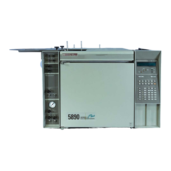
- Page 1 Chemical Analysis Group 5890 Gas Chromatograph 5890 Series II Site Prep Info Document A15282...
- Page 2 Site Prep/Installation Manual HP 5890 Series II and HP 5890 Series II Plus...
- Page 3 Hewlett-Packard Warranty Important User Schallemission Company 1989, 1991, 1993, Information for In Vitro The information contained Werden Meß- und 1994 Diagnostic Applications in this document is subject Testgeräte mit to change without notice. ungeschirmten Kabeln This is a multipurpose All Rights Reserved. product that may be used und/oder in offenen Hewlett-Packard makes no...
-
Page 4: Table Of Contents
Contents Chapter 1 — Site Preparation ..... . Introduction ............Environmental considerations . - Page 5 Contents Connecting power line cord ..........Voltage and grounding .
- Page 6 Site Preparation...
-
Page 7: Chapter 1 - Site Preparation
Site Preparation Introduction This section discusses the site preparation for the HP 5890 SERIES II (hereafter referred to as HP 5890). The following topics are discussed: Environmental considerations Power considerations Gas considerations You will need various supplies to prepare an area for the HP 5890. Hewlett•Packard' s analytical supplies catalog describes the supplies available from Hewlett•Packard.You can obtain a copy from your local sales office. - Page 8 Site Preparation Environmental considerations The HP 5890 is about 50 cm (20 in.) high. The area above the instrument should be clear. Shelves or other overhanging obstructions limit access to the top of the instrument and interfere with cooling. If space is limited, the Oven Exhaust Deflector may improve oven cooling. It diverts exhaust air up and away from the instrument.
-
Page 9: Power Considerations
Site Preparation Power considerations Power considerations Line voltage Your gas chromatograph operates from one of these voltage supplies, depending on the power option ordered. These options and the power cords furnished are described on the next page. 120 VAC single phase (+5, -10%), 48 to 66 Hz, 2200 VA max. (requires a 20 amp dedicated line) 200 VAC split phase (+5, -10%), 48 to 66 Hz, 2200 VA max. - Page 10 Site Preparation Power considerations Option Power and Cord 120 V single phase, 20A for USA. (Standard) 220 V single phase with power cord for use in Europe and Peoples Republic of China. 220 V single phase with power cord for use in Hong Kong. 240 V single phase with power cord for use in Great Britain.
-
Page 11: Gas Considerations
Site Preparation Gas considerations Gas considerations Gases for packed columns The choice of carrier gas depends on the detector selected and what performance is required from it. These relationships are shown below. In general, makeup gases are not needed with packed columns. Gas Recommendations for Packed Columns Detector Carrier Gas... -
Page 12: Gases For Capillary Columns
Site Preparation Gas considerations Gases for capillary columns Hydrogen is the recommended carrier gas for capillary analyses; helium is an acceptable alternate and nitrogen is least desirable. These detectors are compatible with packed columns which use higher carrier gas flow rates than those used with capillary columns. A separate makeup gas system brings total flow into a detector up to the rate for optimum sensitivity with capillary columns. -
Page 13: Gas Purity
Site Preparation Gas considerations Gas purity Some gas suppliers furnish instrument or chromatographic purity grades (the names vary with the supplier) specifically intended for chromatographic use. Use these when available. Gas Purity Recommendations Carrier Gases and Capillary Makeup Gases Helium 99.9995% Nitrogen ”... -
Page 14: Assembling The Gas Plumbing
Site Preparation Assembling the gas plumbing Assembling the gas plumbing Two-Stage Regula- On/Off Valve Main Supply On/Off Valve Moisture Trap Main Gas Supply Oxygen Trap HP 5890 SERIES ll General Plumbing Diagram Follow this general plumbing diagram to prepare gas supply plumbing. Note that: Two•stage(rather than single stage) regulators are strongly recommended to eliminate pressure surges. -
Page 15: Supply Tubing
Site Preparation Assembling the gas plumbing Supply tubing Do not use methylene chloride or any other halogenated solvent for Caution tubing that will be used with an electron capture detector. They will cause elevated baselines and detector noise until they are completely flushed out of the system. -
Page 16: Two-Stage Pressure Regulators
Site Preparation Assembling the gas plumbing Two-stage pressure regulators Two stages of pressure regulation are needed to reduce the very high source pressure to the pressures used by the instrument. The two stages may be combined in a single regulator with a fairly short tubing run to the instrument, or one stage may be at the source with the second stage close to the instrument. -
Page 17: Carrier Gas Miser
Site Preparation Assembling the gas plumbing Carrier gas miser A carrier gas miser reduces the use of carrier gas during off•hours.It reduces two channels of carrier gas flow to a low purging rate during off•hours,without disturbing the pressure regulator or flow controller settings. -
Page 18: Making Swage-Type Connections
Site Preparation Assembling the gas plumbing Making swage-type connections Assemble fitting, bottom tubing Hand-tighten, then wrench-tighten Swage-Type Fittings Assemble the fittings as shown. Push the tubing into the fitting as far as it will go, then tighten the fitting by hand (no wrench). Use a wrench to tighten further (3/4•turnfor 1/8•inchtubing, 1•1/4•turn for 1/4•inch tubing). - Page 19 This page intentionally left blank.
- Page 20 Installation...
-
Page 21: Chapter 2 - Installation
Installation Introduction This section reviews installation for the HP 5890 SERIES II (hereafter referred to as HP 5890). The following topics are discussed: Inspection of shipped materials Instrument cooling Connecting supply gases Connecting cryogenic cooling Power considerations Signal cables Shipment checklist Retain shipping containers and material until contents are checked for completeness and instrument performance is verified. -
Page 22: Site Preparation
Installation Site preparation Site preparation If not already done, refer to Site Preparation in this manual for information concerning proper site preparation. Cooling considerations Cooling: The instrument is cooled convectively: ambient air enters through vents in side panels and from beneath the instrument. Warmed air exits through slots in top, rear, and side panels. -
Page 23: Connecting Supply Gases
Installation Connecting supply gases Connecting supply gases Supply gases are connected either at the main front flow panel, or at auxiliary flow panel(s) mounted behind the door on the left side panel. All inlet supply fittings are 1/8•inchfemale swage•type. is flammable and is an explosion hazard. If H is being connected, WARNING observe safety precautions: be sure the supply is off until all... - Page 24 Installation Connecting supply gases Detector Flow Programmable Cool Manifold Blocks: On-Column Capillary Inlet Flow Module: Carrier Inlet Fit- Detector Gas ting Inlet Fittings Packed Split/Splitless Column Inlet Capillary Flow Module: Inlet Flow Module: Carrier Carrier Inlet Fit- Inlet Fit- ting ting Rear Views, Main Flow Panel (Typical)
-
Page 25: Auxiliary Flow Panels
Installation Connecting supply gases Auxiliary flow panels For auxiliary flow panel(s), follow instructions included with the panel to connect supply tubing between each pressure regulator and the appropriate mass flow controller or flow manifold block, and to connect gas supplies to the pressure regulators. If no supply gas is to be connected directly to an inlet mass flow controller or detector flow manifold block, proceed to Setting initial supply pressures and leak testing in this section. - Page 26 Installation Connecting supply gases 3. For each gas supply to be connected, route its tubing to the appropriate mass flow controller or flow manifold block. Route tubing along the oven wall using slots provided to secure tubing to the wall. If you do not have a packed inlet, continue with gas supply tube connections in this section.
-
Page 27: Changing The Flow Restrictor
Installation Connecting supply gases Changing the flow restrictor You need the following tools to complete this task: a 7/16•inchopen end wrench, a short flathead screwdriver, a pair of tweezers, and the flow restrictor that fits the flow range you need for your analysis. If the gas lines are already connected to the instrument, turn off the carrier gas source and remove the gas line from the carrier gas inlet fitting with a 7/16•inchopen end wrench. - Page 28 Installation Connecting supply gases Flow restrictor Scre Flow controller block Carrier gas inlet fit- ting Plate 3. Remove the flow restrictor from the flow controller with a pair of tweezers. 4. Insert the alternate flow restrictor. Be sure the three O•ringsare in place.
-
Page 29: Gas Supply Tube Connections
Installation Connecting supply gases Flow restrictor Carrier gas inlet fit- ting Plat Scre 7. Replace the carrier gas connector and turn on the gas to a pressure of 50 to 60 psi. Leak test your work. Gas supply tube connections Assemble the fittings as shown. - Page 30 Installation Connecting supply gases Assemble fitting, Hand-tighten, then bottom tubing wrench-tighten For a carrier gas, its tube is connected at the fitting on the appropriate mass flow controller labeled IN. For a capillary makeup gas, its tube is connected at the fitting on the appropriate flow manifold block labeled FID—AUX for an FID or NPD, or TCD—AUX for a TCD or ECD.
-
Page 31: Setting Initial Supply Pressures And Leak Testing
Installation Connecting supply gases Setting initial supply pressures and leak testing Detectors Programmable Cool On-column Capillary Inlet: On/Off Controls Packed Split/Splitless Column Capillary Inlet Inlet: Flow Module: Column Head Pres- sure Mass Flow Mass Flow Controller Controller Septum Purge Flow HP 5890 Flow Controls (Typical) - Page 32 Installation Connecting supply gases After supply gases are connected, the system may be pressurized, and all installed fittings then checked for leaks. 1. At the HP 5890 flow panel, do the following: a. Close all detector on/off valves (fully clockwise). Do the same for capillary makeup gas.
-
Page 33: Connecting Cryogenic Coolant
Installation Connecting supply gases For TCD reference gas, set supply pressure to the appropriate REF on/off valve to 276 kPa (40 psi). For an FID or NPD , set H and air supply pressures to the appropriate HYDROGEN and AIR on/off valves (detector flow manifold block) to 103 kPa (15 psi) and 276 kPa (40 psi), respectively. - Page 34 Installation Connecting supply gases Front Plumbing Connec- tion for Cryogenic Overflow Drain fo Cooling (if installed) Condensation Left Side View The appropriate coolant must be used, based upon the cryogenic option installed•either liquid CO coolant or liquid N coolant. To switch from one coolant to the other, replacement of the entire valve assembly is required•Accessory 19239A for liquid CO , or Accessory 19239B for...
-
Page 35: Gas Supply Checklist
Installation Connecting supply gases Connection between the valve and liquid N supply must be insulated and as short as possible so liquid, rather than gas, is supplied to the inlet valve. Foam tubing used for refrigeration and air•conditioninglines is suitable insulation. Insulation should cover as much as possible. Liquid N cylinders are equipped with a safety relief valve to prevent Caution... -
Page 36: Connecting Power Line Cord
Installation Connecting power line cord Connecting power line cord INTERNAL LINE FUSE 120V +5% -10% 47.5-63Hz 2200 LINE TO NEUTRAL VA MAX Source Line Voltage Label (Typical) Voltage and grounding The source voltage and load rating to be supplied is marked on a label attached at the rear of the instrument. -
Page 37: Turning Power On
Installation Connecting power line cord Red O Visible Right Side On/Off Positions For Main Power Line Switch After placing the instrument where it is to be used, verify the line power switch is off (a red O painted on the forward part of the switch must be visible) before connecting the power line cord. - Page 38 Installation Connecting power line cord Test of display elements: all alpha- OVEN STATUS numeric and LED elements are lit. FINAL RATE TIME INITIAL READ TIME OVEN STATUS HP 5890 memory test in progress. FINAL RATE TIME INITIAL TIME READ HP 5890 Self-testing in progress. OVEN STATUS LEDs off, except possibly NOT...
-
Page 39: Connecting Signal Output Cables
Installation Connecting signal output cables ACTUAL SETPOINT OVEN TEMP Example Display At First Power-on Connecting signal output cables The HP 5890 end of each type of signal cable terminates in a plug. Connection to the HP 5890 is made at receptacles found beneath the right instrument top cover. -
Page 40: Analog Signal Output Cables
Installation Connecting signal output cables Avoid routing cables near the oven exhaust vent or over the top of the Caution instrument; high temperatures in these areas may cause damage. Analog signal output cables The following figure and table show cables available to connect an HP 5890 analog output channel (variable DC signals, +1 V or +1 mV maximum) to a recorder, integrator, and/or A/D converter for a computer system. - Page 41 Installation Connecting signal output cables Note that the general purpose and HP 3350Series LAS analog output cable assemblies consist of two independent cables, terminating together at a common, single, female plug at the HP 5890. One cable is labelled 1 mV, the other +1 V output.
-
Page 42: Instrument Network (Inet) Cable
Installation Connecting signal output cables 2. Connect lead cable(s) to the respective receiving device(s). If spade lug•terminatedwires must be connected directly, note the following with respect to color coding: WHITE + (High) BLACK - (Low) ORANGE Ground 3. Lead the cable(s) out of the instrument at the rear of the signal cable area. - Page 43 Installation Connecting signal output cables Each device to be included in INET communications is connected in series with the next, forming a loop; thus, INET OUT on a given device must be connected to INET IN on the next. The loop must be continuous, and all devices must be on for the loop to function.
-
Page 44: Remote Start/Hp 5890 Ready Cables
Installation Connecting signal output cables 4. Install a second INET cable between the IN receptacle on the HP 5890, and the OUT receptacle on the previous device included in the loop. For an INET system, communication among instruments on the loop should be made only via installed INET cables. -
Page 45: Remote Receptacle
Installation Connecting signal output cables Available Remote Start/HP 5890 Ready Cables Part No. Length 03394-60560 HP 3394/96A Integrator/Controller 05890-61060 HP 3392A Integrator/Controller 05890-61050 HP 3390A Integrator 05890-61070 HP 3350 Series LAS 05890-61080 General Purpose Remote receptacle The 12•pin REMOTE receptacle provides a variety of functions, depending upon connections made via the cable. - Page 46 Installation Connecting signal output cables Available Functions, REMOTE Receptacle Function Description Pin No. 1 Remote Start In TTL input: expects a pulsed relay closure (>5 msec duration) across Pin 1 and any Ground pin. A closure initiates a run by starting the oven temperature program. The run terminates at the HP 5890 by pressing , or by STOP...
- Page 47 Installation Connecting signal output cables Available Functions, REMOTE Receptacle Function Description Pin No. 5 & 6 or 5 & 9 Ready Out Two sides of a single-pole, double-throw relay; ready is signaled by the contacts opening (Pins 5 & 6), or by contacts closing (Pins 5 & 9). Ready occurs when the following conditions are met: The HP 5890 is not in a run.
- Page 48 Installation Connecting signal output cables The variety of functions available makes custom•designedoperating systems possible. Some examples include: A simple push•buttonswitch installed across Pins 1 & 2 permits starting the HP 5890 from a remote location. In performing manual injections, for example, it is quite convenient to have remote start capability located in the inlet area to minimize time delays between starting the HP 5890 and injecting sample.
-
Page 49: Rs-232 And Hpib/Rs-232 Cables
Installation Connecting signal output cables At injection, the sampler controller simultaneously must signal the integrator to begin integrating data, and must start the HP 5890 oven temperature program (via Pins 1 & 2). Where the HP 5890 is to be started from a remote device, it is convenient to have indication as to whether or not the HP 5890 is ready. -
Page 50: Hp-Ib/Rs-232 Interface Board Information
Installation HP-IB/RS-232 interface board information HP-IB/RS-232 interface board information Remove the top right cover and the right side panel from the instrument. Locate the eight•toggleS1 Switch on the HP•IB/RS•232 interface board. Notice that each of the eight toggles can be positioned toward the main board or the outer edge of the interface board. - Page 51 Installation HP-IB/RS-232 interface board information If you desire an RS•232configuration (the bottom toggle toward the board's outer edge), the top three toggles must be set to establish the baud rate. Use the table below to set the toggles (note that a toggle on means that it is set toward the board's outer edge).
- Page 52 Installation HP-IB/RS-232 interface board information 5. Test 4 will verify your selection of type of interface and either its address or its baud rate. Pressing the number 4 on the keypad will display a message RS-232 Baud = the selected rate or HP-IB Addr the selected address.
-
Page 53: Analog Input Board Information
Installation Analog input board information If an INET loop is to be used, install the loop cables. If an INET is not being used, leave the INET cable between an in and out in place. Connect the appropriate HP•IBor RS•232cable to the connector board. Replace all of the instrument's panels and covers.