Table of Contents
Advertisement
Quick Links
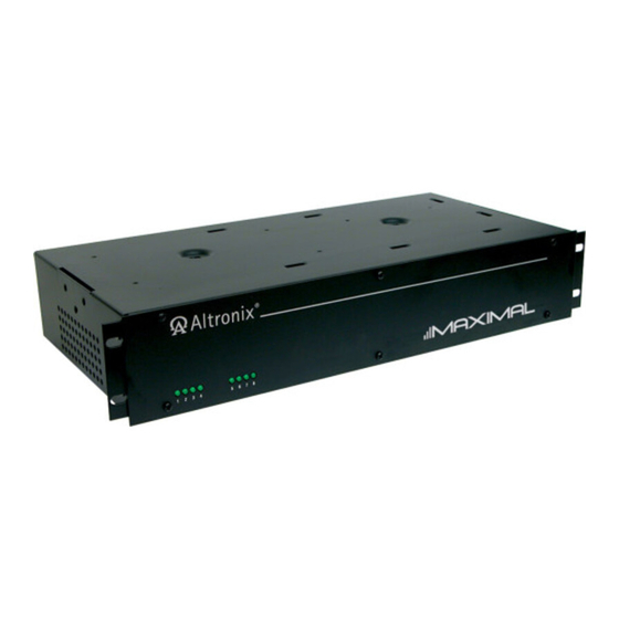
Rack Mount Series
Installation Guide
Models include:
Maximal1RHDV
- 12VDC @ 4A or 24VDC @ 3A.
- Eight (8) PTC Protected Outputs.
Maximal3RHDV
- 12VDC or 24VDC @ 6A.
- Eight (8) PTC Protected Outputs.
Maximal33RDV
- 12VDC and/or 24VDC @ 12A.
- Sixteen (16) PTC Protected Outputs.
Rev. 090109
Maximal1RDV
- 12VDC @ 4A or 24VDC @ 3A.
- Sixteen (16) PTC Protected Outputs.
Maximal3RDV
- 12VDC or 24VDC @ 6A.
- Sixteen (16) PTC Protected Outputs.
More than just power.
TM
Advertisement
Table of Contents

Related Manuals for Altronix Maximal1RHDV


Summary of Contents for Altronix Maximal1RHDV
- Page 1 Rack Mount Series Installation Guide Models include: Maximal1RHDV Maximal1RDV - 12VDC @ 4A or 24VDC @ 3A. - 12VDC @ 4A or 24VDC @ 3A. - Eight (8) PTC Protected Outputs. - Sixteen (16) PTC Protected Outputs. Maximal3RHDV Maximal3RDV - 12VDC or 24VDC @ 6A.
-
Page 2: Table Of Contents
Table of Contents: Overview pg. 3 . . . . . . . . . . . . . . . . . . . . . . . . . . . . . . . . . . . . . . . . . . . . . . . . . . . . . . . . . . . . . . . . . . . . . . . . . . . . . . . . . . . . . . . . . . . . . . . . . Maximal Rack Mount Series Configuration Chart . -
Page 3: Overview
Overview: Altronix Maximal Rack Mount Seriesunits distribute and switch power to access control systems and accessories . They convert a 220VAC (working range 198VAC - 256VAC), 50/60Hz input into eight (8) or sixteen (16) inde- pendently controlled 12VDC and/or 24VDC PTC protected outputs . Outputs are activated by an normally open (NO) or normally closed (NC) dry trigger input from an Access Control System, Card Reader, Keypad, Push Button, PIR, etc . -
Page 4: Installation Instructions
Connect the Normally Open or Normally Closed input triggers from the access control devices to the removable terminals marked [IN1 and GND] through [IN8 and GND] for Maximal1RHDV and Maximal3RHDV . For Maximal1RDV, Maximal3RDV and Maximal33RDV connect devices to the second set of terminals marked [IN1 and GND] through [IN8 and GND] . -
Page 5: Maintenance
FACP Signal Circuit (Polarity Reversal) . Normally Closed [NC] Trigger Input . Normally Open [NO] Trigger Input . Output Voltage and Stand-by Specification Charts: 20 Min. of 4 Hr. of 24 Hr. of Altronix Model Power Supply Board Battery Backup Backup Backup 12VDC/40AH* 3 .5A... -
Page 6: Power Supply Board Output Voltage Settings
Power Supply Board Output Voltage Settings: Fig. 1 Fig. 1a OFF - 24V ON - 12V OFF - 24V ON - 12V Maximal1RHDV, Maximal1RDV Maximal3RHDV, Maximal3RDV, Power Supply Board Maximal33RDV Power Supply Boards - 6 - MaximalRDV Rack Access Power Controllers (PTC) -
Page 7: Fire Alarm Interface, Output Selection, And Input Type
Fire Alarm Interface, Output Selection, and Input Type: Fig. 2 Output Trigger LEDs FIRE ALARM INTERFACE OUTPUT SELECT ACM8R-S Fig. 2a Fig. 2b OFF - NC Input ON - NO Input DIP Switches for FACP and Output DIP Switch for Programming NO or NC Input Output Trigger LEDs... -
Page 8: Power Supply Boards Drawings
Power Supply Board Maximal1RHDV, Maximal1RDV Fig. 4 Power Supply Board AC DC 5A 250V C NO NC C – BAT + – DC + Fig. 4a Fig. 4b --- BAT – BAT + C NO NC C Battery and Built-in... -
Page 9: Facp Hook-Up Diagrams
FACP Hook-Up Diagrams Polarity Reversal Input from FACP Signal Circuit Output (Polarity is referenced in alarm condition) Fig. 7 Fig. 6 5-30VDC 5-30VDC from FACP from FACP FACP FACP Signal Circuit Signal Circuit RESET Factory Installed Normally Open [NO] RESET Jumper Reset Switch Latching... -
Page 10: Mounting Options
Mounting Options: Fig. 12 Mounting Hardware (Included): Two (2) mounting brackets . Eight (8) flat head screws for mounting brackets . Eight (8) pan head screws Remove center brace for faceplate . from rack mount chassis before proceeding with installation . Rack Mount Installation 1 . - Page 11 Notes: MaximalRDV Rack Access Power Controllers (PTC) - 11 -...
-
Page 12: Rack Mechanical Drawing And Dimensions
Altronix is not responsible for any typographical errors . 140 58th Street, Brooklyn, New York 11220 USA | phone: 718-567-8181 | fax: 718-567-9056 website: www .altronix .com | e-mail: info@altronix .com | Lifetime Warranty | Made in U .S .A . MEMBER...
Need help?
Do you have a question about the Maximal1RHDV and is the answer not in the manual?
Questions and answers