Table of Contents
Advertisement
Quick Links
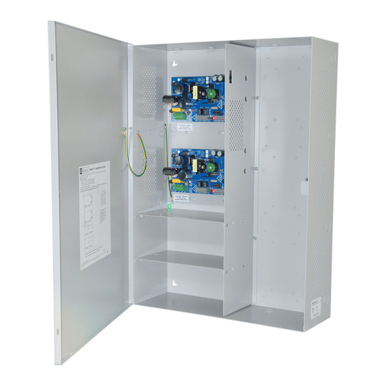
Maximal FE Series
Expandable Power Systems
Models Include:
Maximal11FE
- Power Supply 1: 12VDC or 24VDC @ 4A.
- Power Supply 2: 12VDC or 24VDC @ 4A.
Maximal13FE
- Power Supply 1: 12VDC or 24VDC @ 4A.
- Power Supply 2: 12VDC or 24VDC @ 6A.
Maximal33FE
- Power Supply 1: 12VDC or 24VDC @ 6A.
- Power Supply 2: 12VDC or 24VDC @ 6A.
Maximal35FE
- Power Supply 1: 12VDC or 24VDC @ 6A.
- Power Supply 2: 12VDC @ 10A.
Installation Guide
Rev. MFE052319
Installing Company: _______________ Service Rep. Name: __________________________________
Address: _____________________________________________ Phone #: __________________
Altronix Corp.
140 58th St. Brooklyn, NY
Maximal37FE
- Power Supply 1: 24VDC @ 10A.
- Power Supply 2: 12VDC or 24VDC @ 6A.
Maximal55FE
- Power Supply 1: 12VDC @ 10A.
- Power Supply 2: 12VDC @ 10A.
Maximal75FE
- Power Supply 1: 24VDC @ 10A.
- Power Supply 2: 12VDC @ 10A.
Maximal77FE
- Power Supply 1: 24VDC @ 10A.
- Power Supply 2: 24VDC @ 10A.
More than just power.
TM
Advertisement
Table of Contents

Related Manuals for Altronix Maximal FE Series


Summary of Contents for Altronix Maximal FE Series
- Page 1 Maximal FE Series Expandable Power Systems Models Include: Maximal11FE Maximal37FE - Power Supply 1: 12VDC or 24VDC @ 4A. - Power Supply 1: 24VDC @ 10A. - Power Supply 2: 12VDC or 24VDC @ 4A. - Power Supply 2: 12VDC or 24VDC @ 6A.
-
Page 2: Table Of Contents
Maximal FE Series Configuration Chart ........ -
Page 3: Maximal Fe Overview
Prevents deep battery discharge. • Overvoltage protection. Fuse Ratings: Battery Backup: • Refer to Maximal FE series Configuration Chart, pg. 5. • Built-in charger for sealed lead acid or Visual Indicators: gel type batteries. • Maximum charge current 1.54A. -
Page 4: Agency Listings
UL Listings for Canadian Installations: ULC-S319-05 - Electronic Access Control Systems Class I equipment. CSA C22.2 No.205 - Signal Equipment. Altronix Corp. 140 58th St. Brooklyn, NY California State Fire Marshal Approved. *ANSI/UL 294 7th Ed. Access Control Performance Levels: Destructive Attack - I;... -
Page 5: Maximal Fe Series Configuration Chart
Maximal FE Series Configuration Chart: Nominal DC Output Voltage Options Power Supply 1 Power Supply 2 [DC] [AUX] [DC] [AUX] Altronix Model Number eFlow4NB eFlow4NB 10.1- 10.05- 10.1- 10.05- – – – – 13.2 13.2 13.2 13.2 Maximal11FE – 5A/250V 7.5A/32V... -
Page 6: Maximal Fe Installation Instructions
4. Measure output voltage before connecting devices. This helps avoiding potential damage. 5. Connect devices or Altronix sub-assembly modules to be powered to the terminals marked [– DC +] (Fig. 2, pg. 9). For auxiliary device connection, this output will not be affected by Low Power Disconnect or Fire Alarm Interface. -
Page 7: Maintenance
Connect 120VAC 60Hz to these terminals: L to hot, N to neutral. Do not use the [G] terminal + DC – Refer to Maximal FE Series Configuration Chart, pg. 5. Trigger EOL Fire Alarm Interface trigger input from a short or FACP. Trigger inputs can be normally open, Supervised normally closed from an FACP output circuit (Class 2 power-limited input). -
Page 8: Power Supply Board Stand-By Battery Specifications
Power Supply Board Stand-by Battery Specifications eFlow4NB: Battery Access Control Applications Stand-by 30 Mins./4A* 12AH 35 Mins./4A* 40AH Over 4 Hours/4A* 65AH Over 4 Hours/4A* eFlow6NB: Battery Access Control Applications Stand-by 10 Mins./6A 12AH 30 Mins./6A* 40AH Over 4 Hours/6A* 65AH Over 4 Hours/6A* eFlow102NB:... -
Page 9: Battery Setup And Tamper Switch Installation
Fig. 2 Tamper Switch Fig. 2a Enclosure AC DC 1 min enable NC C NO NC C NO TRIGGER +AUX- 2 hr disable AC FAIL BAT FAIL SUPERVISED RESET Line Neutral Edge of Input 120VAC 60Hz Enclosure Earth Tamper Switch Ground (not included) To Access Control Panel or... -
Page 10: Nec Power-Limited Wiring Requirements For Maximal Fe
NEC Power-Limited Wiring Requirements: Power-limited and non power-limited circuit wiring must remain separated in the cabinet. All power-limited circuit wiring must remain at least 0.25” away from any non power-limited circuit wiring. Furthermore, all power-limited circuit wiring and non power-limited circuit wiring must enter and exit the cabinet through different conduits. One such example of this is shown below. -
Page 11: Enclosure Dimensions
(21.6mm) 4” (101.6mm) 2” (50.8mm) 19” (482.6mm) Altronix is not responsible for any typographical errors. –––––––––––––––––––––––––––––––––––––––––––––––––––––––––––––––––––––––––––––––––––––––––––––––––––––––––––––––– 140 58th Street, Brooklyn, New York 11220 USA | phone: 718-567-8181 | fax: 718-567-9056 website: www.altronix.com | e-mail: info@altronix.com | Lifetime Warranty IIMaximal FE Series... - Page 12 - UL Listed in the U.S. and Canada. - Local or remote control of up to (2) two Altronix eFlow power output(s) via LAN and/or WAN. - Monitor real time diagnostics: DC output voltage, output current, AC & battery status/service, input trigger state change, output state change and unit temperature.
Need help?
Do you have a question about the Maximal FE Series and is the answer not in the manual?
Questions and answers