Table of Contents
Advertisement
Quick Links
Expandable Power Systems
Installation Guide
Models Include:
MaxFit3FE
- 12VDC/24VDC @ 6A.
MaxFit5FE
- 12VDC @ 10A.
MaxFit7FE
- 24VDC @ 10A.
Rev. MFEPS080119
Installing Company: ________________ Service Rep. Name: ______________________________________
Address: ___________________________________________________ Phone #: _____________________
More than just power.
TM
Advertisement
Table of Contents

Subscribe to Our Youtube Channel
Related Manuals for Altronix Maximal Fit Series


Summary of Contents for Altronix Maximal Fit Series
-
Page 1: Installation Guide
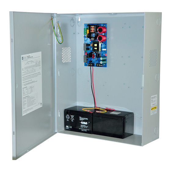
Expandable Power Systems Installation Guide Models Include: MaxFit3FE - 12VDC/24VDC @ 6A. MaxFit5FE - 12VDC @ 10A. MaxFit7FE - 24VDC @ 10A. Rev. MFEPS080119 More than just power. Installing Company: ________________ Service Rep. Name: ______________________________________ Address: ___________________________________________________ Phone #: _____________________... - Page 2 MaxFitFE Series Overview: Altronix MaxFit Expandable Power Systems provide system designers and installers with optimum power choices and the highest levels of versatility. They provide 12VDC or 24VDC via single output power supply/ charger. Includes AC fail, low battery, and battery presence monitoring. Enclosure accommodates up to four (4) 12VDC/12AH batteries.
-
Page 3: Maintenance
4. Measure output voltage before connecting devices. This helps avoiding potential damage. 5. Connect devices or Altronix sub-assembly modules to be powered to the terminals marked [– DC +] (Fig. 1h, pg. 4). For auxiliary device connection, this output will not be affected by Low Power Disconnect or Fire Alarm Interface. -
Page 4: Power Supply Board Output Voltage Settings
Fig. 1 - eFlow Board configuration 10A 32V 5A 250V 5A 250V BAT FAIL AC FAIL AC DELAY SHUTDOWN 1 min. enable TRIGGER EOL NC C NO NC C NO + AUX – 2 hr. disable SUPERVISED RESET Power Supply Board Output Voltage Settings: Fig. -
Page 5: Terminal Identification
Terminal Identification: Terminal Function/Description Legend Connect 120VAC 60Hz to these terminals: L to hot, N to neutral. L, N Do not use terminal marked [G] (Fig. 1a, pg. 4). + DC – Refer to MaxFitFE Series Configuration Chart, pg. 2 (Fig. 1h, pg. 4). Trigger EOL Fire Alarm Interface trigger input from a short or FACP. -
Page 6: Nec Power-Limited Wiring Requirements
NEC Power-Limited Wiring Requirements: Power-limited and non power-limited circuit wiring must remain separated in the cabinet. All power-limited circuit wiring must remain at least 0.25” away from any non power-limited circuit wiring. Furthermore, all power-limited circuit wiring and non power-limited circuit wiring must enter and exit the cabinet through differ- ent conduits. - Page 7 Notes: - 7 - MaxiFit3FE/MaxFit5FE/MaxFit7FE Expandable Power Systems...
- Page 8 7.00” 1.25” Altronix is not responsible for any typographical errors. 140 58th Street, Brooklyn, New York 11220 USA | phone: 718-567-8181 | fax: 718-567-9056 website: www.altronix.com | e-mail: info@altronix.com | Lifetime Warranty | Made in U.S.A. MEMBER IIMaxFit3FE/5FE/7FE Series H21S...
Need help?
Do you have a question about the Maximal Fit Series and is the answer not in the manual?
Questions and answers