Table of Contents
Advertisement
Quick Links
Advertisement
Table of Contents

Related Manuals for MKS 649A


Summary of Contents for MKS 649A
- Page 1 121004-P1 Rev A, 11/97 Instruction Manual MKS Type 649A Pressure Controller with an Integral Mass Flow Meter Six Shattuck Road Fax: (978) 975-0093 Andover, MA 01810-2449 E-mail: mks@mksinst.com (800) 227-8766 or (978) 975-2350 Web site: http://www.mksinst.com...
- Page 2 For the period commencing with the date of shipment of this equipment and ending two years later, MKS will, at its option, either repair or replace any part which is defective in materials or workmanship or with respect to the date-related operations warranty without charge to the purchaser.
- Page 3 121004-P1 Rev A, 11/97 MKS Type 649A Pressure Controller with an Integral Mass Flow Meter...
- Page 4 All rights reserved. No part of this work may be reproduced or transmitted in any form or by any means, electronic or mechanical, including photocopying and recording, or by any information storage or retrieval system, except as may be expressly permitted in writing by MKS Instruments, Inc.
-
Page 5: Table Of Contents
Table of Contents Table of Contents Safety Information........................1 Symbols Used in This Instruction Manual..............1 Symbols Found on the Unit ..................2 Chapter One: General Information..................5 Introduction ....................... 5 Design Features of the Integral Mass Flow Meter .......... 5 Cleanliness Features .................. - Page 6 Table of Contents Chapter Three: Overview .......................21 General Information ....................21 Pressure Control Range..................21 Flow Range ....................22 A Typical Control System................22 How The 649 Pressure Controller Works..............23 Flow Measurement Overview..................24 Flow Path ......................24 Measurement Technique ................24 Tuning the 649 Pressure Controller ................25 Proportional Term..................25 Integral Term ....................26 Tuning the 649 Controller................27...
- Page 7 Table of Contents Performance Specifications ..................45 Physical Specifications ....................46 Environmental Specifications..................47 Trip Point Specifications.................... 47 Appendix B: Model Code Explanation .................. 49 Model Code....................... 49 Appendix C: Valve Orifice Selection..................53 General Information....................53 Checking the Valve Orifice Size..............53 How To Verify the Orifice Selection................
- Page 8 Table of Contents...
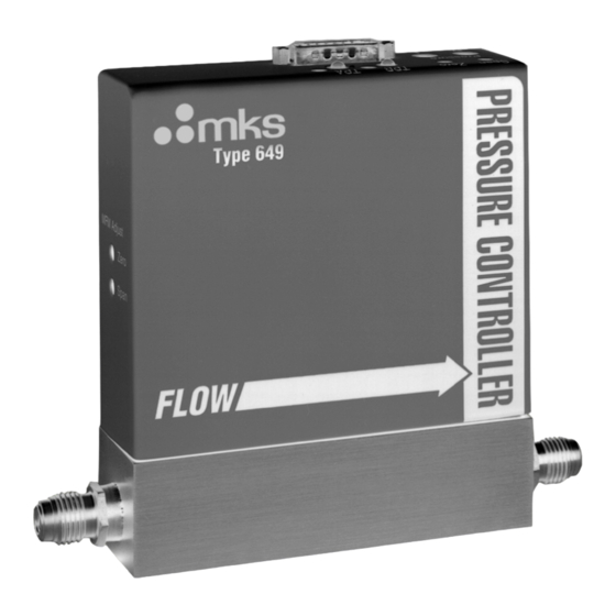
- Page 9 List of Figures List of Figures Figure 1: Front View of the Type 649 Controller..............13 Figure 2: Back View of the Type 649 Controller ..............14 Figure 3: Side View (Inlet) of the Type 649 Controller............14 Figure 4: Bottom View of the Type 649 Controller..............15 Figure 5: Downstream Pressure Control ................
- Page 10 List of Figures viii...
- Page 11 List of Tables List of Tables Table 1: Definition of Symbols Found on the Unit ..............2 Table 2: I/O Connector Pinout....................18 Table 3: Initial Configuration ....................20 Table 4: Highest Pressure for Zero Adjustment of the Pressure Transducer.......34 Table 5: Valve Orifice Size ......................53 Table 6: Valve Orifice Index Number..................54...
- Page 12 List of Tables...
-
Page 13: Safety Information
Safety Information Safety Information Symbols Used in This Instruction Manual Definitions of WARNING, CAUTION, and NOTE messages used throughout the manual. Warning The WARNING sign denotes a hazard. It calls attention to a procedure, practice, condition, or the like, which, if not correctly performed or adhered to, could result in injury to personnel. -
Page 14: Symbols Found On The Unit
Safety Information Symbols Found on the Unit The following table describes symbols that may be found on the unit. Definition of Symbols Found on the Unit Protective earth (ground) Off (Supply) Earth (ground) On (Supply) IEC 417, No.5019 IEC 417, No.5017 IEC 417, No.5008 IEC 417, No.5007 Frame or chassis... - Page 15 DO NOT SUBSTITUTE PARTS OR MODIFY INSTRUMENT Do not install substitute parts or perform any unauthorized modification to the instrument. Return the instrument to an MKS Calibration and Service Center for service and repair to ensure that all safety features are maintained.
- Page 16 Safety Information USE PROPER FITTINGS AND TIGHTENING PROCEDURES All instrument fittings must be consistent with instrument specifications, and compatible with the intended use of the instrument. Assemble and tighten fittings according to manufacturer's directions. CHECK FOR LEAK-TIGHT FITTINGS Before proceeding to instrument setup, carefully check all plumbing connections to the instrument to ensure leak-tight installation.
-
Page 17: Chapter One: General Information
One Type “D” connector, located on the top of the unit, accepts the input power and has both the pressure (input and output) and flow (output) signals. You can connect the 649 controller to an MKS Type 247 or 246 Mass Flow Controller Power Supply/Readout or a Type 647 Mass Flow and Pressure Programmer/Display unit. -
Page 18: Cleanliness Features
How This Manual is Organized Chapter One: General Information Cleanliness Features The design of the pressure controller ensures extremely low external leakage and minimizes a key source of particle generation, outgassing, and permeation. The design also incorporates minimal wetted surface area. To further ensure its cleanliness, the 649 controller undergoes precision machining as well as a proprietary cleaning process. -
Page 19: Customer Support
Number) from the MKS Calibration and Service Center before shipping. The ERA Number expedites handling and ensures proper servicing of your instrument. Please refer to the inside of the back cover of this manual for a list of MKS Calibration and Service Centers. - Page 20 Customer Support Chapter One: General Information This page intentionally left blank.
-
Page 21: Chapter Two: Installation
Chapter Two: Installation How To Unpack the Type 649 Unit MKS has carefully packed the Type 649 unit so that it will reach you in perfect operating order. Upon receiving the unit, however, you should check for defects, cracks, broken connectors, etc., to be certain that damage has not occurred during shipment. -
Page 22: Unpacking Checklist
How To Unpack the Type 649 Unit Chapter Two: Installation Unpacking Checklist Standard Equipment: • Type 649 Unit • Type 649 Instruction Manual (this book) Optional Equipment: • Electrical Connector Accessories Kit - 649A-K1 • Interface cables (refer to Interface Cables, page 11) -
Page 23: Interface Cables
Use a CB649S-1-xx or CB649-1-xx cable (where xx indicates the length) to connect the 649 controller to an MKS Type 247 or 246 Mass Flow Controller Power Supply/Readout or a Type 647 Mass Flow and Pressure Programmer/Display unit. The standard cable, CB649-1-10, is 10 feet in length. -
Page 24: Product Location And Requirements
Warning Follow your corporate policy for handling toxic or hazardous gases. Your corporate policy on handling these gases supersedes the instructions in this manual. MKS assumes no liability for the safe handling of such materials. • Install the 649 controller in a “flowing” system where gas is continually added and evacuated Do not use the controller in a “dead-ended”... -
Page 25: Dimensions
Chapter Two: Installation Dimensions • Verify that your pressure system can withstand pressure equal to the full scale range of the pressure transducer Your pressure system may be exposed to the full scale pressure since the 649 controller will control over the entire full scale range of the pressure transducer. As a precaution, you may choose to install a safety valve in your system to vent excess pressure. -
Page 26: Side View
649A12T21CAVR Flow: 20 SCCM Gas: N2 Pressure: 100 TORR MKS I nst r um en t s, In c. Made in t he USA Figure 2: Back View of the Type 649 Controller Side View The flow meter adjustments are located on the inlet side of the 649 controller. -
Page 27: Bottom View
Chapter Two: Installation Dimensions Bottom View Mounting Hole Outlet Fitting 0.38 (9.5) 0.38 (9.5) Inlet Fitting Mounting Hole: 8-32 UNC-2B x 0.340 DP. 3.18 (80.7) 0.79 (20) 2 places Figure 4: Bottom View of the Type 649 Controller... -
Page 28: Setup
Setup Chapter Two: Installation Setup This section covers how to install the 649 controller into your system. Fittings The 649 pressure controller is available with the following fittings: • Cajon 4-VCR male compatible • Cajon 8-VCR male compatible Mounting Hardware The 649 controller has two mounting holes located on the bottom or base of the unit. -
Page 29: Installing The Unit
Chapter Two: Installation Setup Installing the Unit The 649 Pressure Controller should be mounted to provide downstream pressure control. Connect the controller so that the flow arrow points toward the system whose pressure you need to control. Note Connect the 649 controller to your system so that the gas flows in the direction of the flow arrow on the front of the unit. -
Page 30: Electrical Information
Electrical Information Chapter Two: Installation Electrical Information I/O Connector The 649 controller has one 15-pin, male Type “D” connector that provides the pressure output, set point input, and trip point output signals. Refer to Figure 6, page 21, for the location of the connector. - Page 31 Chapter Two: Installation Electrical Information Set Point Input (Pin 8) The set point input signal can be a 0 to 10 Volt (factory setting) or 0 to 5 Volt signal. The range of the set point input signal must match the range of the pressure output signal. The 649 controller is initially configured for a 0 to 10 Volt pressure output signal.
-
Page 32: Initial Configuration
Initial Configuration Chapter Two: Installation Initial Configuration The 649 pressure controller is shipped from the factory with the configuration listed in Table 3. Initial Configuration Feature Setting Options Pressure Control Downstream no option Set Point Input* 0 to 10 V 0 to 5 V Pressure Output 0 to 10 V... -
Page 33: Chapter Three: Overview
Chapter Three: Overview General Information Chapter Three: Overview General Information Figure 6 shows the top view of the 649 pressure controller. The user adjustable controls for pressure zero, pressure span, the P term, the I term, and the trip points are located on the top of the controller. -
Page 34: Flow Range
The 649 Pressure Controller provides the first three components. The pressure transducer is an MKS Baratron capacitance manometer. The 649 unit contains the electronics necessary for pressure control. The control valve included in the 649 controller is a proportional control valve. -
Page 35: How The 649 Pressure Controller Works
Chapter Three: Overview How The 649 Pressure Controller Works How The 649 Pressure Controller Works The 649 controller compares the pressure reading to the set point, and positions the valve to maintain, or achieve, the set point pressure. The controller functions as a PI (Proportional- Integral) controller. -
Page 36: Flow Measurement Overview
Flow Measurement Overview Chapter Three: Overview Flow Measurement Overview The 649 controller measures the mass flow rate of a gas. Flow Path Upon entering the 649 controller, the gas stream passes first through the metering section of the instrument for its mass flow to be measured. The gas moves on through the control valve, which regulates the pressure according to the given set point, and then exits the instrument at the established pressure. -
Page 37: Tuning The 649 Pressure Controller
Chapter Three: Overview Tuning the 649 Pressure Controller Tuning the 649 Pressure Controller Tuning optimizes the way the 649 unit controls your system. The Proportional (P) and Integral (I) terms adjust the response of the 649 controller. The controller responds to changes in either the pressure of the system or the value of the set point. -
Page 38: Integral Term
Tuning the 649 Pressure Controller Chapter Three: Overview Integral Term The action of the Integral (I) term creates a valve drive signal that is proportional to the magnitude and sign of the area under the error signal curve (error signal with respect to time). Therefore, as time passes, the integral term acts to position the valve to reduce the error signal to zero. -
Page 39: Tuning The 649 Controller
Chapter Three: Overview Tuning the 649 Pressure Controller Tuning the 649 Controller Tuning the 649 controller involves adjusting the Proportional and Integral terms to optimize the response of the controller in your system. Since every system is different, the optimum settings for the P term and I term will vary. -
Page 40: Figure 11: Controller Response With Increased P Term
Tuning the 649 Pressure Controller Chapter Three: Overview Controller Response with Increased P Term Increasing the P term to 1 while holding the I term at 0 yields: Settling Time Settling Time P = 1 Set Point I = 0 Signal Time Figure 11: Controller Response with Increased P Term... -
Page 41: Priority Of Commands
Chapter Three: Overview Priority of Commands Priority of Commands The 649 controller has an established hierarchy that it uses to determine which commands take precedence. The commands and operating modes are listed according to the order of priority (from highest to lowest): •... -
Page 42: Trip Points
Trip Points Chapter Three: Overview Trip Points The 649 controller provides two trip points (Trip Point A and Trip Point B). Each trip point operates independently and controls an open collector output that can be connected to an external relay. Each trip point has an adjustment pot, a status LED, and a test jack. Refer to Figure 6, page 21, for the location of the trip point adjustment pots and LEDs. -
Page 43: Applications With A Large Differential Pressure
European directives. The serial number label is located on the back of the unit. Serial #: 000098221 Model #: 649A12T21CAVR Flow: 20 SCCM Gas: N2 Pressure: 100 TORR MKS In stru ment s, Inc. Made in t he USA Figure 13: Serial Number Label... -
Page 44: The Gas Correction Factor (Gcf) For Flow Metering
Polyatomic gases Note 1. When using the GCF, the accuracy of the flow reading may vary by ±5%, however, the repeatability will remain ±0.2% of F.S. 2. All MKS readouts have Gas Correction Adjustment controls to provide direct readout. -
Page 45: Chapter Four: Operation
Check the pressure transducer zero before operating the unit initially and then periodically as required. The zero can be set (or reset) by adjusting the zero potentiometer located on the top cover of the 649 controller or, on the front panel of an MKS Power Supply/Readout, if you are using one. -
Page 46: How To Adjust The Pressure Transducer Span
How To Adjust the Pressure Transducer Span pot in conjunction with a calibration transfer standard. Do not adjust the Only adjust the SPAN span setting if a calibration transfer standard is not available. Instead, contact an MKS Service Center for calibration. -
Page 47: How To Zero The Integral Mass Flow Meter
Chapter Four: Operation How To Zero the Integral Mass Flow Meter How To Zero the Integral Mass Flow Meter Ensure that no gas flow is entering the 649 controller. 1. Apply gas, at a regulated pressure, to the 649 controller. 2. -
Page 48: How To Tune The 649 Controller
How To Tune the 649 Controller Chapter Four: Operation How To Tune the 649 Controller You may need to tune the 649 controller to optimize how it controls your system. Tuning consists of varying the P (Proportional) and I (Integral) parameters to achieve the fastest, smoothest response to changes in the set point value. -
Page 49: How To Adjust The Trip Point Values
Chapter Four: Operation How To Adjust the Trip Point Values How To Adjust the Trip Point Values Equipment required: digital volt meter (DVM) ” hex or open-ended wrench Caution Only qualified individuals should perform the adjustments. You must comply with all the necessary ESD and handling precautions while adjusting the instrument. -
Page 50: How To Select The Trip Point Action
How To Select the Trip Point Action Chapter Four: Operation Refer to Figure 6, page 21, for the location of the trip point adjustment pots. Turning the pot clockwise raises the trip point setting. 7. Repeat steps 1 and 2 to adjust TP B. 8. -
Page 51: Figure 14: Jumper Positions On The Transducer Board
Chapter Four: Operation How To Select the Trip Point Action Jumper Blocks JP1 and JP2 determine the range of the Trip Point pressure output signal Test Jacks JP3 Jumper Block sets TPB action JP4 Jumper Block sets TPA action Figure 14: Jumper Positions on the Transducer Board 6. -
Page 52: How To Use Trip Points As Error Indicators
How To Use Trip Points as Error Indicators Chapter Four: Operation How To Use Trip Points as Error Indicators You can use the trip points to indicate when the error signal deviates from a given range. The error is defined as the difference between the actual pressure reading and the set point. For example, assume you have a 100 Torr unit and your set point is 50 Torr. -
Page 53: How To Change The Pressure Output Signal Range
4. Position the controller with the front side facing you, and pull up on the enclosure to remove it. The MKS logo is displayed on the front of the unit. The board assembly will be visible, with the Transducer board facing you. The Control board is connected to the back of the Transducer board. - Page 54 How To Change the Pressure Output Signal Range Chapter Four: Operation 10. Attach the hex nuts, removed in step 3, to the I/O connector. 11. Reconnect the leads and wires.
-
Page 55: Chapter Five: Maintenance
It is also recommended that the instrument be recalibrated annually if no other time interval has been specifically established. Refer to the inside of the back cover of this instruction manual for a complete list of MKS Calibration and Service centers. - Page 56 Zero Adjustment Chapter Five: Maintenance This page intentionally left blank.
-
Page 57: Appendix A: Product Specifications
Appendix A: Product Specifications Performance Specifications Appendix A: Product Specifications Performance Specifications Accuracy ±0.5% Reading Pressure Transducer ≤ ±0.1% F.S. Pressure Controller Mass Flow Meter ±1.0% F.S. CE Compliance EMC Directive 89/336/EEC Electromagnetic Compatibility Control Adjustments Integral 10 positions (0 through 9) Proportional 8 positions (0 through 7;... -
Page 58: Physical Specifications
Physical Specifications Appendix A: Product Specifications Physical Specifications ≥1500 psig Burst Pressure Dimensions 1.5 in x 4.75 in (less fittings) x 5.55 in max. 3.81 cm x 12.07 cm (less fittings) x 14.1 cm max. Fittings Cajon 4-VCR male compatible, 8-VCR male compatible Full Scale Ranges... -
Page 59: Environmental Specifications
Appendix A: Product Specifications Environmental Specifications Environmental Specifications Ambient Operating Temperature Range 0° to 50° C (32° to 122° F) Storage Temperature Range -20° to 80° C (-4° to 176° F) Storage Humidity Range 0 to 95% Relative Humidity, non-condensing Trip Point Specifications Trip Points Two open collector transistors, adjustable from 1 to 100%... - Page 60 Trip Point Specifications Appendix A: Product Specifications This page intentionally left blank.
-
Page 61: Appendix B: Model Code Explanation
The options of your 649 unit are identified in the model code when you order the unit. The model code is identified as follows: 649AXXXYYYZAB where: XXX YYY 649A Type Number Pressure Range Flow Rate Valve Orifice Size Valve Plug Seat Material Fittings Type Number (649A) This designates the model number of the instrument. - Page 62 Model Code Appendix B: Model Code Explanation Full Scale Pressure Range (XXX) The full scale pressure range is indicated by a two digit/one letter code. Full Scale Pressure Range Ordering Code 10 Torr 20 Torr 50 Torr 100 Torr 1000 Torr Flow Rate (N equivalent) Full Scale (YYY) The flow rate full scale is indicated by a two digit/one letter code.
- Page 63 Appendix B: Model Code Explanation Model Code Valve Plug Seat Material (A) The valve plug seat material is specified by a single letter code. Valve Plug Seat Material Ordering Code Metal Viton Kel-F Kalrez Fittings (B) The choice of fittings is indicated by a single letter code. Fittings Ordering Code Cajon 4-VCR, male...
- Page 64 Model Code Appendix B: Model Code Explanation This page intentionally left blank.
-
Page 65: Appendix C: Valve Orifice Selection
Appendix C: Valve Orifice Selection General Information Appendix C: Valve Orifice Selection General Information The 649 controller is available in four valve orifice sizes. You should confirm that the valve orifice in your 649 controller is the correct size for your application before you install it into your system. -
Page 66: How To Verify The Orifice Selection
How To Verify the Orifice Selection Appendix C: Valve Orifice Selection How To Verify the Orifice Selection The correct orifice depends on three pieces of information: the upstream pressure, the downstream pressure, and the flow rate. These instructions assume that you are using nitrogen gas. -
Page 67: Figure 15: Flow Range Selection
Appendix C: Valve Orifice Selection How To Verify the Orifice Selection 3. Use the index number and your maximum flow rate, to determine the orifice size from Figure 15. Each line represents the maximum flow rate for the orifice. Choose the orifice number above your point on the graph to ensure that the orifice can deliver the required flow. -
Page 68: Using Different Gases
How To Verify the Orifice Selection Appendix C: Valve Orifice Selection Using Different Gases The valve orifice selection data is based on nitrogen gas. If you will be using a gas other than nitrogen, you need to compensate for the density difference between nitrogen and your process gas before you can select the appropriate valve orifice. - Page 69 Appendix C: Valve Orifice Selection How To Verify the Orifice Selection Example 2: Using Helium (He) Following the example in How To Verify the Orifice Selection, page 54, using 100% helium: 1. Calculate the orifice sizing factor, using the equation on page 56. The standard density of He is 0.179, so the orifice sizing factor is: 1.250 2.64 Orifice Sizing Factor...
- Page 70 How To Verify the Orifice Selection Appendix C: Valve Orifice Selection Example 3: Using 30% Hydrogen (H 2 ) and 70% Nitrogen (N 2 ) Using a mixture of gases, such as 30% hydrogen and 70% nitrogen, may impact the orifice size. Following the example in How To Verify the Orifice Selection, page 54, with this gas mixture: 1.
-
Page 71: Appendix D: Gas Correction Factors
Appendix D: Gas Correction Factors Appendix D: Gas Correction Factors SYMBOL SPECIFIC HEAT, Cp DENSITY CONVERSION cal/g o C g/l @ 0 o C FACTOR - - - 0.240 1.293 1.00 Ammonia 0.492 0.760 0.73 1.39 1 Argon 0.1244 1.782 Arsine 0.1167 3.478... - Page 72 Appendix D: Gas Correction Factors SYMBOL SPECIFIC HEAT, Cp DENSITY CONVERSION cal/g o C g/l @ 0 o C FACTOR Dichlorosilane 0.150 4.506 0.40 1,2-Dichlorotetrafluoroethane 0.160 7.626 0.22 (Freon - 114) 1,1-Difluoroethylene 0.224 2.857 0.43 (Freon - 1132A) 2,2-Dimethylpropane 0.3914 3.219 0.22 Ethane...
- Page 73 Appendix D: Gas Correction Factors SYMBOL SPECIFIC HEAT, Cp DENSITY CONVERSION cal/g o C g/l @ 0 o C FACTOR Hydrogen Chloride 0.1912 1.627 1.00 Hydrogen Fluoride 0.3479 0.893 1.00 Isobutylene 0.3701 2.503 0.29 Krypton 0.0593 3.739 1.543 Methane 0.5328 0.715 0.72 Methyl Fluoride...
- Page 74 0.161 8.360 0.20 (Freon - 113) Tungsten Hexafluoride 0.0810 13.28 0.25 Xenon 0.0378 5.858 1.32 Empirically defined Consult MKS Instruments, Inc. for special applications. NOTE: Standard Pressure is defined as 760 mmHg (14.7 psia). Standard Temperature is defined as 0...
-
Page 75: Index
Index Index Accuracy, 51 Gas correction factor, 32, 59 Ambient temperature, 12, 47 I/O connector, 18 Baratron, 5 Inlet pressure, 16 Installation, 13 Integral control, 20, 21, 23, 26, 27, 36 Commands, priority, 29 Connector, I/O, 18–19 Control range, pressure, 21 Label, 31 Control system, 22 Customer support, 7... - Page 76 Index Pressure output signal, 18, 20 Valve orifice, 53–58 Pressure, inlet, 16 Valve test point, 18 Process control, 20, 23–26 Proportional control, 20, 21, 23, 25, 27, 36 Zero mass flow meter, 35 Range, 50 transducer, 33–34 Returning the product, 7, 9 Safety procedures and precautions, 2 Set point, 19 Set point input, 20...
Need help?
Do you have a question about the 649A and is the answer not in the manual?
Questions and answers