
Related Manuals for MKS MKSINST IE500A


Summary of Contents for MKS MKSINST IE500A
- Page 1 Type IE500A / IE1000A Mass Flow Controller Instruction Manual MKSINST 2 Tech Drive 1052292-001 Rev A Suite 201 07/14 Andover, MA 01810 978.645.5500 978.557.5100 FAX www.mksinst.com...
- Page 2 For the period commencing with the date of shipment of this equipment and ending one (1) year later, MKS will, at its option, either repair or replace any part which is defective in materials or workmanship or with respect to the date-related operations warranty without charge to the purchaser.
- Page 3 1052292-001 Rev A 07/14 Type IE500A / IE1000A Mass Flow Controller 2 Tech Drive Suite 201 Andover, MA 01810 978.645.5500 978.557.5100 FAX www.mksinst.com...
- Page 4 All rights reserved. No part of this work may be reproduced or transmitted in any form or by any means, electronic or mechanical, including photocopying and recording, or by any information storage or retrieval system, except as may be expressly permitted in writing by MKS Instruments, Inc. Printed in the United States of America MKSINST ...
-
Page 5: Table Of Contents
Table of Contents Table of Contents Mass Flow Device Safety Information ......................1 Symbols Used in This Instruction Manual ........................1 Symbols Found on the Unit ............................1 Safety Procedures and Precautions ..........................2 Sicherheitshinweise für das Massenflussgerät ....................3 In dieser Betriebsanleitung vorkommende Symbole ..................... - Page 6 4-20 mA IO 15-pin Interface Operation ........................28 General Operational Functions ............................ 30 Chapter Four: Maintenance and Troubleshooting ..................33 General Information ..............................33 Zeroing the MKS IE1000A High Flow Rate Mass Flow Controller ................33 Customer Support ................................ 36 Repair ..................................36 Troubleshooting ................................37 Chapter Five: Diagnostic Interface Setup, Configuration, and Operation ..........
- Page 7 List of Figures List of Figures Figure 1: Front View of the IE500A / IE1000A MFC ..................21 Figure 2: Bottom View of the IE500A / IE1000A MFC .................. 21 Figure 3: End View of the IE500A / IE1000A MFC ..................22 Figure 4: Top View of the IE500A / IE1000A MFC (analog IO Interface) .............
- Page 8 表 5: 本機器に使用されているマークについて ...................... 9 표 6: 장치에 표시된 기호들의 정의 ......................11 Table 7: MKS Interface Cables ........................25 Table 8: Analog I/O 15-pin DSUB Pinouts (Model Code B) ................26 Table 9: 4-20 mA I/O 15-pin DSUB Pinouts (Model Code G) ................ 28...
-
Page 9: Mass Flow Device Safety Information
Mass Flow Device Safety Information Mass Flow Device Safety Information Symbols Used in This Instruction Manual Definitions of WARNING, CAUTION, and NOTE messages used throughout the manual. Warning The WARNING sign denotes a hazard. It calls attention to a procedure, practice, condition, or the like, which, if not correctly performed or adhered to, could result in injury to personnel. -
Page 10: Safety Procedures And Precautions
Do not install substitute parts or perform any unauthorized modification to the instrument. Return the instrument to an MKS Calibration and Service Center for service and repair to ensure that all safety features are maintained. SERVICE BY QUALIFIED PERSONNEL ONLY Operating personnel must not remove instrument covers. -
Page 11: Sicherheitshinweise Für Das Massenflussgerät
Sicherheitshinweise für das Massenflussgerät Sicherheitshinweise für das Massenflussgerät In dieser Betriebsanleitung vorkommende Symbole Bedeutung der mit WARNUNG!, VORSICHT! und HINWEIS gekennzeichneten Absätze in dieser Betriebsanleitung. Warnung! Das Symbol WARNUNG! weist auf eine Gefahr für das Bedienpersonal hin. Es macht auf einen Arbeitsablauf, eine Arbeitsweise, einen Zustand oder eine sonstige Gegebenheit aufmerksam, deren unsachgemäße Ausführung bzw. -
Page 12: Sicherheitsvorschriften Und Vorsichtsmaßnahmen
Ersetzen Sie keine Teile mit baugleichen oder ähnlichen Teilen, und nehmen Sie keine eigenmächtigen Änderungen am Gerät vor. Schicken Sie das Gerät zwecks Wartung und Reparatur an den MKS-Kalibrierungs- und -Kundendienst ein. Nur so wird sichergestellt, dass alle Schutzvorrichtungen voll funktionsfähig bleiben. -
Page 13: Informations De Sécurité Pour Appareils De Mesure/Contrôle De Débit Massique
Informations de sécurité pour appareils de mesure/contrôle de débit massique Informations de sécurité pour appareils de mesure/contrôle de débit massique Symboles utilisés dans ce manuel d'utilisation Définitions des indications AVERTISSEMENT, ATTENTION, et REMARQUE utilisées dans ce manuel. Avertissement L'indication AVERTISSEMENT signale un danger pour le personnel. Elle attire l'attention sur une procédure, une pratique, une condition, ou toute autre situation présentant un risque d'accident pour le personnel, en cas d'exécution incorrecte ou de non-respect des consignes. -
Page 14: Mesures De Sécurité Et Précautions
Ne pas installer de pièces de remplacement ni effectuer des modifications non autorisées sur l'appareil. Renvoyer l'appareil à un centre de service et de calibrage MKS pour tout dépannage ou réparation afin de garantir le l'intégrité des dispositifs de sécurité. -
Page 15: Medidas De Seguridad Del Dispositivo De Flujo De Masa
Medidas de seguridad del dispositivo de flujo de masa Medidas de seguridad del dispositivo de flujo de masa Símbolos usados en este manual de instrucciones Definiciones de los mensajes de advertencia, precaución y de las notas usados en el manual. Advertencia El símbolo de advertencia indica la posibilidad de que se produzcan daños personales. -
Page 16: Procedimientos Y Precauciones De Seguridad
No instale piezas que no sean originales ni modifique el instrumento sin autorización. Para asegurar el correcto funcionamiento de todos los dispositivos de seguridad, envíe el instrumento al Centro de servicio y calibración de MKS toda vez que sea necesario repararlo o efectuar tareas de mantenimiento. -
Page 17: マスフロー機器の安全に関する情報
マスフロー機器の安全に関する情報 マスフロー機器の安全に関する情報 本取扱説明書のマーク 本マニュアルでは警告、注意、ポイントのマークを用いて重要な事項を記載しています。 警告 この表示を無視して誤った取り扱い (手順や使用方法、条件など) をすると、人が重傷 を負う可能性が想定される内容を示しています。必ずお読みください。 注意 この表示を無視して誤った取り扱い (手順や使用方法など) をすると、 製品が損傷する 可能性が想定される内容を示しています。必ずお読みください。 ポイント この表示は手順や使用方法、条件などに関する重要な情報が記載されていることを示 しています。必ずお読みください。 本機器のマーク 以下の表では、本機器に使用されているマークについて説明いたします。 表 5: 本機器に使用されているマークについて オン (電源) オフ (電源) 接地 (アース) 保護接地 (アース) IEC 417, No. 5007 IEC 417, No. 5008 IEC 417, No. 5017 IEC 417, No. -
Page 18: 安全対策について
マスフロー機器の安全に関する情報 安全対策について 本機器を使用する際は、必ず以下の安全対策を守ってください。これらの安全対策や本マニュアルの 警告を無視すると、機器本来の用途の安全基準を侵害することになり、機器が提供する保護機能が 損なわれる可能性があります。MKS Instruments, Inc. は、顧客側の安全対策の不履行に対して は一切責任を負いかねます。 勝手に部品を変えたり、本体を改造しないこと 本機器に代用部品を使用したり、不正な改造を加えないでください。すべての安全システムを正しく機能させるた めの修理やメンテナンスが必要な場合は、本機器を MKS Calibration and Service Center まで戻してください。 修理は必ず専門の修理サービスを利用すること オペレータは絶対に本機器を分解しないでください。部品の交換や内部の調整は必ず専門の修理サービスを利 用してください。 電流が通じている回路から切断すること 電源ケーブルを接続したままで部品を交換しないでください。特定の状況では、電源ケーブルを取り外した状態 でも危険な電圧が残っている場合があります。感電などの事故を防ぐため、回路に触れる前に必ず電源から切 断し、放電してください。 危険な材料を使用する場合は慎重に機器を使用すること 危険な材料を使用する場合は、使用者は各自の責任の元で適切な安全対策を講じてください。必要に応じて 本機器を浄化してください。また、使用する材料に対するシーリング材の耐久性を確認してください。 機器を浄化すること 本機器を取り付けた後やシステムから取り外す前に、きれいな乾燥ガスで本機器を浄化し、使用した材料を完 全に取り除いてください。 浄化する場合は適切な手順で行うこと 本機器の浄化は換気フードの下で行う必要があります。また、浄化作業を行う人は必ず手袋を着用してください。 爆発の危険性のある環境で機器を使用しないこと 爆発が起きるのを防ぐため、本機器を爆発の危険性のある環境で使用しないでください。ただし、そのような環境 での使用が特別に保証されている場合は除きます。 適切な金具類を使用し、手順に従って金具の締めを行うこと 金具類は本機器の仕様と一致し、機器本来の用途に適合したものである必要があります。金具類の取り付け や締めは、製造業者の指示に従ってください。 液体の漏れがないよう接続箇所を確認すること... -
Page 19: 질량 유량 장치 안전 정보
준수하지 않거나 본 매뉴얼의 다른 부분에 있는 특정 경고를 준수하지 않을 경우, 기계 사용 목적의 안전 기준을 위반하는 것이 되며, 장비가 제공하는 보호기능을 손상시킬 수 있습니다. MKS Instruments, Inc.는 고객이 본 요건을 준수하지 않는 경우에 대해서는 어떠한 책임도 지지 않습니다. - Page 20 질량 유량 장치 안전 정보 교체 부품을 설치하거나 기계에 허가되지 않은 어떠한 수정도 가하지 마십시오. 서비스와 수리가 필요한 경우에는 모든 안전 특성이 유지되도록 기계를 MKS 보정 서비스 센터(MKS Calibration and Service Center)로 보내주십시오. 자격이 있는 사람에게만 서비스를 받으십시오 작동하는 사람은 기계 겉면을 제거해서는 안됩니다. 부품 교체 및 내부 조정은 자격이 있는 서비스...
-
Page 21: How This Manual Is Organized
Appendix C: Health and Safety Form provides a copy of the safety form (at the time of this manual’s release) which must be filled out prior to return of the instrument to MKS for calibration, routine maintenance, or repair. Failure to include the form with a returned shipment will delay processing at the MKS Calibration and Service Center. - Page 22 This page intentionally left blank.
-
Page 23: Chapter One: General Information
The MFC integrates thermal sensor technology together with MKS model based, adaptive, real-time feedback control to provide typical flow control response times of approximately 2 seconds to changes in setpoint. -
Page 24: Operation Of The Mfc With Gases Other Than Air
The current MKS library of gases and functions is in excess of 120 in number and includes most gases in common use within the process industries. - Page 25 Chapter One: General Information Operation of the MFC with Gases other than Air The IE500A / IE1000A High Flow Rate Mass Flow Controller is calibrated with clean, filtered, dry air rated to stringent ISO standards for compressed air systems. When running with air, humidity may have a minor effect (usually <...
- Page 26 This page intentionally left blank.
-
Page 27: Chapter Two: Installation
If you find any damage, notify your carrier and MKS immediately. If it is necessary to return the unit to MKS, obtain an RMA Number (Return Material Authorization Number) from the MKS Calibration and Service Center before shipping. Please refer to the inside of the back cover of this manual for a list of MKS Calibration and Service Centers. - Page 28 40 psid The standard valve configuration provides control over this differential pressure range with the outlet at atmospheric pressure. If process conditions vary significantly from those listed, contact an MKS applications engineer for assistance in tuning the unit for optimum performance.
-
Page 29: Understanding Dimensional Constraints
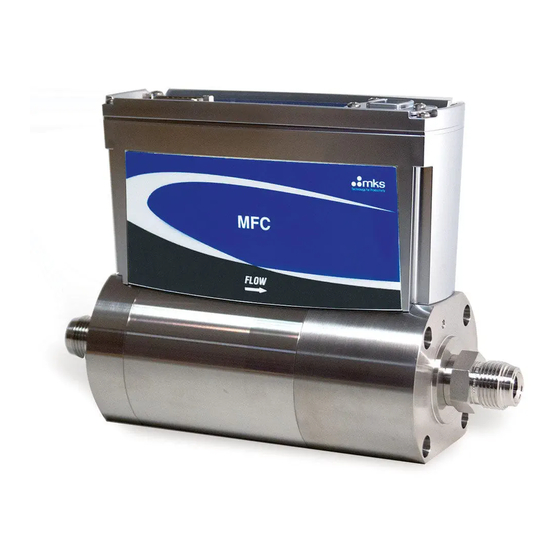
Chapter Two: Installation Understanding Dimensional Constraints Understanding Dimensional Constraints Refer to the applicable drawings, which follow. Front and Rear Views The front of the IE500A / IE1000A MFC has an arrow to indicate the direction of gas flow through the unit. The back of the IE500A / IE1000A MFC contains the connector pin-outs. -
Page 30: Figure 3: End View Of The Ie500A / Ie1000A Mfc
Understanding Dimensional Constraints Chapter Two: Installation End View Figure 3: End View of the IE500A / IE1000A MFC Top View Figure 4: Top View of the IE500A / IE1000A MFC (analog IO Interface) -
Page 31: Performing Mfc Installation
Chapter Two: Installation Performing MFC Installation Labels Each IE500A / IE1000A High Flow Rate Mass Flow Controller contains a serial number label on the inlet end of the product’s electrical enclosure. The serial number label shows the “as-shipped” model code, the full scale flow range, and the name plate gas. - Page 32 Performing MFC Installation Chapter Two: Installation 4) Flow clean, dry purge gas across the fittings to minimize particle contamination prior to and during installation. Use only purge gases that are approved for your process. 5) Connect the process gas supply remembering to tighten the seal gaskets according to the fitting manufacturer’s or seal gasket manufacturer’s recommendation.
-
Page 33: Chapter Three: Operation
CB259S-5. Analog I/O User Supplied Shielded Cable Requirements MKS offers a full line of cables for most MKS equipment. Should you choose to manufacture your own cables, follow the guidelines listed below: 1. The cable must have an overall metal braided shield, covering all wires. Neither aluminum foil nor spiral shielding will be as effective;... -
Page 34: Table 8: Analog I/O 15-Pin Dsub Pinouts (Model Code B)
Analog 15-pin Interface Operation Chapter Three: Operation 5. In selecting the appropriate type and wire size for cables, consider: Voltage ratings. Cumulative I R heating of all the conductors (keep them safely cool). IR drop of the conductors, so that adequate power or signal voltage gets to the device. ... - Page 35 (For a 0 to 10 V input range, contact the MKS Applications Department.) A common application of this feature is for pressure control using input from a pressure transducer.
-
Page 36: 4-20 Ma Io 15-Pin Interface Operation
4-20 mA IO 15-pin Interface Operation Chapter Three: Operation 4-20 mA IO 15-pin Interface Operation The IE500A / IE1000A High Flow Rate Mass Flow Controller 4-20 mA I/O interface type is available in a 15-pin DSUB male connector for providing power and signal I/O. 4-20 mA I/O 15-pin Pinouts Table 9: 4-20 mA I/O 15-pin DSUB Pinouts (Model Code G) 15-pin 4-20 mA Pin Descriptions... - Page 37 Chapter Three: Operation 4-20 mA IO 15-pin Interface Operation 4-20 mA IO Valve Override The valve override feature enables the control valve to be fully opened (purged) or closed independent of the setpoint command signal. For a 4-20 mA IO interface: ...
-
Page 38: General Operational Functions
Gas Calibration Tables The default (instance 32) clean dry air (CDA) gas calibration table (500 slm or 1000 slm) created at the MKS factory is tagged in a manner which prevents editing or deletion in the field. This ensures that vital calibration information is not lost during subsequent gas creation and range adjustment activities. -
Page 39: Figure 7: Effects Of The Proportional Term (High Proportional Term)
Chapter Three: Operation General Operational Functions Figure 7: Effects of the Proportional Term (High Proportional Term) Integral Term The action of the Integral (I) term creates a valve drive signal that is proportional to the magnitude and sign of the area under the error signal curve (error signal with respect to time). Therefore, as time passes, the integral term acts to position the valve to reduce the error signal to zero. - Page 40 General Operational Functions Chapter Three: Operation Derivative Term The action of the Derivative (D) term creates a valve drive signal that is proportional to the rate of change of the error signal over time. In moderate amounts, it can be used to reduce overshoot within the system by adding predictive capabilities to the control algorithm.
-
Page 41: Chapter Four: Maintenance And Troubleshooting
The components used in the MKS IE1000A High Flow Rate Mass Flow Controller have a long history of usage and are expected to comply with the specifications listed. - Page 42 Zeroing the MKS IE1000A High Flow Rate Mass Flow Chapter Four: Maintenance and Troubleshooting Controller Preparing to Execute Zero Adjustment Zeroing a flow sensor at a real flow above its stated minimum resolution creates a zero flow offset relative to the true absolute zero flow.
- Page 43 Chapter Four: Maintenance and Troubleshooting Zeroing the MKS IE1000A High Flow Rate Mass Flow Controller b) Wait 20 seconds while the mass flow controller performs the zero adjustment process. c) Verify that the zero offset has changed. OPTION 2: Diagnostic Interface...
-
Page 44: Customer Support
A returned instrument will not be examined without a signed Health and Safety form indicating that the unit is free of harmful materials. The Health and Safety form can be obtained on the last page of this manual or through the MKS website at: http://www.mksinst.com/service/servicehowtoorder.aspx. -
Page 45: Troubleshooting
Chapter Four: Maintenance and Troubleshooting Troubleshooting Troubleshooting Table 10: MFC Troubleshooting Chart Symptoms Possible Cause Remedy MFC does not respond to setpoint MFC power has been turned off * Verify the device is powered with the correct and reports near zero flow input voltage at power supply (valve current remains 0) Incorrect cable used to connect MFC... - Page 46 Troubleshooting Chapter Four: Maintenance and Troubleshooting MFC flow output exceeds full MFC has been given improper * Verify setpoint signal range between pins scale rated flow analog setpoint signal listed in Chapter 3: Operation for interface type and check proper signal ground (valve current is max 260 mA) MFC has been given VALVE OPEN * Verify valve override pin is not grounded to...
- Page 47 Chapter Four: Maintenance and Troubleshooting Troubleshooting MFC flow output matches Actual process gas does not match * Verify actual process gas in use matches programmed setpoint but actual current gas instance for MFC programmed gas instance in CONFIG mode independently measured gas flow of diagnostic interface exceeds allowable accuracy error Low vapor pressure gas has...
- Page 48 This page intentionally left blank.
-
Page 49: Chapter Five: Diagnostic Interface Setup, Configuration, And Operation
Step 1: Install the Java™ Plug-In Chapter Five: Diagnostic Interface Setup, Configuration, and Operation Chapter Five: Diagnostic Interface Setup, Configuration, and Operation The auxiliary interface is a supplemental digital interface that can be used for diagnostics and monitoring purposes. It is not used to control the IE500A / IE1000A Mass Flow Controller during normal operation. To access the diagnostic features of the mass flow controller through the on-board auxiliary interface, follow Steps 1 and 2 before proceeding to the section titled “Step 3: Connect to the IE500A / IE1000A Mass Flow Controller”. -
Page 50: Step 2: Configure Tcp/Ip Settings For Communication To Ie1000A
Step 2: Configure TCP/IP Settings for Communication to Chapter Five: Diagnostic Interface Setup, Configuration, and IE1000A Operation Figure 10: Java Download Window 2. Follow the onscreen prompts to install the Java application. Step 2: Configure TCP/IP Settings for Communication to IE1000A In order to communicate to an MFC through the Ethernet interface, the host computer must have a unique, static IP address which is in the same general format as the MFC. -
Page 51: Figure 11: Windows 7 Network Information Window
Chapter Five: Diagnostic Interface Setup, Configuration, Step 2: Configure TCP/IP Settings for Communication to and Operation IE1000A Figure 11: Windows 7 Network Information Window 3. Double click on the local area connection to open the status window as shown below. Figure 12: Windows 7 LAN Stats Dialog Box 4. -
Page 52: Figure 13: Windows 7 Lan Properties Dialog Box
Step 2: Configure TCP/IP Settings for Communication to Chapter Five: Diagnostic Interface Setup, Configuration, and IE1000A Operation Figure 13: Windows 7 LAN Properties Dialog Box 5. Left click to highlight <Internet Protocol Version 4 (TCP/IPv4)>. Select <Properties> 6. A new pop up will appear related to “Internet Protocol Version 4 (TCP/IPv4) Properties” which allows you to change the default IP address of the communication port: Figure 14: Windows 7 IP Properties Dialog Box 7. -
Page 53: Step 3: Connect To The Ie1000A High Flow Rate Mass Flow Controller
Chapter Five: Diagnostic Interface Setup, Configuration, Step 3: Connect to the IE1000A High Flow Rate Mass Flow and Operation Controller 9. Hit the <Tab> key on the left hand side of the keyboard and a subnet mask is automatically entered. 10. -
Page 54: Monitor Mode
Monitor Mode Chapter Five: Diagnostic Interface Setup, Configuration, and Operation Monitor Mode “Monitor Mode” allows the user to monitor the IE500A / IE1000A High Flow Rate Mass Flow Controller’s performance. In order to configure the mass flow controller, (which includes zeroing the device, changing IP addresses, and creating new process gases), the “Setup”... - Page 55 Chapter Five: Diagnostic Interface Setup, Configuration, Monitor Mode and Operation Monitor Mode / Plot Page The Monitor Mode / Plot Page shows real-time performance of the device. From this page, the user is able to select the variables to plot, the rate at which to plot them, and the filename under which to save the data that has been plotted.
-
Page 56: Figure 16: Ie1000A Embedded Interface (Monitor Mode / Plot Page)
MFC either individually or all at once. In the “Snapshot” section, the user can acquire device setup data that will allow MKS to diagnose a device problem remotely. Both of these sections are explained in detail below. -
Page 57: Figure 17: Ie1000A Embedded Interface (Monitor Mode / Diagnostics Page)
Chapter Five: Diagnostic Interface Setup, Configuration, Monitor Mode and Operation To run this test select, select the “Temperature:” checkbox, and then press the “Run the Test” button. When the test finishes, the test result “Pass” or “Fail” will be displayed next to the checkbox. -
Page 58: Figure 18: Ie1000A Embedded Interface (Monitor Mode / Configuration Page)
Monitor Mode Chapter Five: Diagnostic Interface Setup, Configuration, and Operation Figure 18: IE1000A Embedded Interface (Monitor Mode / Configuration Page) -
Page 59: Setup Mode
Chapter Five: Diagnostic Interface Setup, Configuration, Setup Mode and Operation Setup Mode In “Setup Mode” the user is able to configure the MFC, i.e. zero the device, change the IP address, configure the PID parameters, etc. To enter this mode, while in “Monitor Mode”, go to the “Configuration Page” and enter the Factory-shipped password “config”... -
Page 60: Figure 20: Ie1000A Embedded Interface (Setup Mode / Device Page)
Setup Mode Chapter Five: Diagnostic Interface Setup, Configuration, and Operation Setup Mode / Device Page In “Setup Mode” this page gives you the ability to modify the gas settings. Figure 20: IE1000A Embedded Interface (Setup Mode / Device Page) Gas Settings: The Device Page enables the user to change the MFC’s gas settings. To change the gas settings review the following possible operations on the following pages. -
Page 61: Figure 21: Ie1000A Embedded Interface (Setup Mode / Device Page) Creating A New Gas Instance
Chapter Five: Diagnostic Interface Setup, Configuration, Setup Mode and Operation 4. This process typically takes under one minute to complete. When the process is completed, the browser will display a green banner across the top of the Device Page that says, “Gas Selection Update SUCCEEDED.”... -
Page 62: Figure 23: Ie1000A Embedded Interface (Setup Mode / Plot Page)
Setup Mode Chapter Five: Diagnostic Interface Setup, Configuration, and Operation The figure below is a screen capture of the Plot Page in “Setup Mode.” The control parameter section is located above the “Select Variables” section in the top right-hand corner of the page. This page enables you to send a setpoint to the MFC through Ethernet (see notes below), watch the MFC’s performance on the plot, and adjust the PID parameters accordingly to optimize the performance of the MFC. -
Page 63: Figure 24: Ie1000A Embedded Interface (Setup Mode / Configuration Page)
Chapter Five: Diagnostic Interface Setup, Configuration, Setup Mode and Operation Setup Mode / Configuration Page As was noted earlier, the Configuration Page is where you are initially directed once you’ve entered “Setup Mode.” Here the MFC can be zeroed, the “Setup Mode” password can be changed, changes can be made to the Ethernet settings and firmware can be updated. - Page 64 Setup Mode / Configuraton Page / Updating Firmware Updating firmware is the responsibility of your local MKS representative. If any updates are “necessary”, then your local representative will be in contact to set up a time to complete the upgrade. Please note that a...
-
Page 65: Figure 25: Ie1000A Embedded Interface (Setup Mode / Optional Pc Page)
Chapter Five: Diagnostic Interface Setup, Configuration, Setup Mode and Operation Setup Mode / Optional PC Page (Analog 15 pin MFC’s Only) The Setup Mode / Optional PC page is only available in Setup Mode for analog 15-pin devices. Here the MFC can be setup to control to an external signal, e.g. - Page 66 Setup Mode Chapter Five: Diagnostic Interface Setup, Configuration, and Operation Optional Input Kp, Optional Input Ki, Optional Input Kd: These values are the PID parameters for Optional Input control. Typically these will be set to match the standard Kp, Ki and Kd values that are factory set before shipment.
-
Page 67: Figure 26: Ie1000A Embedded Interface (Setup Mode / Plot Page) Enabled Optional Input
Chapter Five: Diagnostic Interface Setup, Configuration, Setup Mode and Operation Figure 26: IE1000A Embedded Interface (Setup Mode / Plot Page) Enabled Optional Input The Optional PID parameters are always settable on the plot page, but they will have no effect unless the Optional Input is enabled. -
Page 68: Figure 27: Ie1000A Embedded Interface Calibration Sheet
Setup Mode Chapter Five: Diagnostic Interface Setup, Configuration, and Operation Figure 27: IE1000A Embedded Interface Calibration Sheet... -
Page 69: Appendix A: Product Specifications
Appendix A: Product Specifications Performance Specifications Appendix A: Product Specifications Performance Specifications Full Scale Flow equivalent) 250 to 500 slm IE500A 501 to 1000 slm IE1000A Max Inlet Pressure 150 psig Normal Operating Pressure Differential 40 - 50 psid (dependent on fitting type) (ATM pressure @ MFC outlet port) Burst Pressure 1500 psig... -
Page 70: Environmental Specifications
Environmental Specifications Appendix A: Product Specifications Environmental Specifications 10 to 50 C (50 to 122 F) Ambient Operating Temperature Range -20 to 65 C (-4 to 149 F) Storage Temperature Range Storage Humidity Range 0 to 95% RH, non-condensing Electrical Specifications 15-pin ANALOG Input Power +15 - 24 V... -
Page 71: Appendix B: Model Code Explanation
The gas which the MFC is intended to control is identified by its SEMI Gas Code. A partial listing is shown below. The full list is shown in SEMI Document E052-00-0611 and may be found on the SEMI website, www.semi.org, or a complete list shown on the MKS website at www.mksinst.com. Gas Name... - Page 72 Model Code Description Appendix B: Model Code Explanation Nitrous Oxide Octafluorocyclobutane (R-c318) Oxygen Mass Flow Full Scale Range (FFF) The IE500A / IE1000A High Flow Rate Mass Flow Controller’s full scale range is indicated by a three digit combination where the flow rate is expressed in sccm. The first two digits of this code represent the most significant digits of the flow full scale range in exponential form separated by a decimal.
- Page 73 Initial Release Note Unless otherwise specified, MKS will ship firmware current to date of order. To receive previous software revision levels, please specify to customer service at order placement. For assistance with configuring your IE500A / IE1000A High Flow Rate Mass Flow Controller, please...
- Page 74 This page intentionally left blank.
-
Page 75: Appendix C: Health And Safety Form
Appendix C: Health and Safety Form Model Code Description Appendix C: Health and Safety Form...
Need help?
Do you have a question about the MKSINST IE500A and is the answer not in the manual?
Questions and answers