
Related Manuals for MKS 647C


Summary of Contents for MKS 647C
- Page 1 Multi Channel Flow Ratio/Pressure Controller Type 647C Instruction Manual MKS Instruments Deutschland GmbH Rev. 2009-07...
- Page 2 MKS Instruments. Cajon ® and VCR ® are registered trademarks of Cajon Company, Macedonia, Ohio Kalrez ®...
-
Page 3: Table Of Contents
647C Contents Contents 1. General............................ 1 1.1 The Multi Gas Controller (MGC) Type 647C............1 1.2 CE conformity......................1 1.3 Options ........................2 1.4 Software ........................2 1.5 Technical Specifications................... 3 1.6 Drawings ........................4 1.6.1 Front Panel....................4 1.6.2 Rear Panel ....................5 1.7 Safety Information .................... - Page 4 4.2 Command Syntax ..................... 35 4.3 Table of Commands ....................36 4.4 Response Syntax ..................... 39 5. Application of the 647C ......................41 5.1 Mass Flow Controllers....................41 5.2 Trouble Shooting ...................... 42 6. Pin Assignment of rear connectors ..................43 6.1 RS232 connector......................
-
Page 5: General
1. General 1. General 1.1 The Multi Gas Controller (MGC) Type 647C The 647C is designed to control Mass Flow Controllers (MFC) with complex requirements to the process. It allows different configurations. Various master/slave configurations within several groups of channels. -
Page 6: Options
1. General 647C 1.3 Options The available options are identified in the model code: 647C – X – Y – C – R where: Options Designation Channels (X): Four Eight Interface (Y): RS-232 Control Option (C): None Relay Option (R):... -
Page 7: Technical Specifications
(3) Relative humidity within the specified temperature range. (4) For use in closed heatable rooms, without condensation. (5) of max. signal, within the range of operation temperature. Fuses inside the instruments may only be replaced by service people from MKS Instruments. Figure 1: Technical Specifications... -
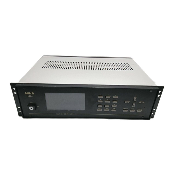
Page 8: Drawings
1. General 647C 1.6 Drawings 1.6.1 Front Panel Tec hno log y for Pr oduc tiv ity 0/ALL ENTER CLEAR M ULTI GAS CONTROLLER 647C A = Monitor (LCD Display) B = Keyboard Figure 2: Front Panel... -
Page 9: Rear Panel
3/7 = Channel 3 or 7 for MFC 4/8 = Channel 4 or 8 for MFC = Connector ACCESS 10 = Connector RELAY 11 = Connector PRESSURE 12 = Connector RS232 13 = Connector SERVICE (to be used only by MKS) Figure 3: Rear Panel... -
Page 10: Safety Information
Cleaning of the device must performed, if it is disconnected from power supply and if the cleaning is performed dry. The device may be opened by MKS service personel only. If the device Warning is open, danger for life (by high voltage) may occur. -
Page 11: Installation
If you have problems booting the system, you should refer to the chapter “Reset of System” and “Applications of the 647C”. Powering Off Before switching off the instrument it is recommended to switch off all flow channels and (if necessary) the pressure control mode. -
Page 12: Symbols At The Case
The type label gives information about the device type, the serial number and some technical date. The label close to the fuse holder tells the specification of spare fuses: T2A, 250V. 1.10 Accessories The 647C comes with the following accessories: Sub-D connector sets for the instruments: 4 channel device: ZB-19... -
Page 13: Cables
The cables listed for type 647A and 647B are the same as for the type 647C. 1.12 Service In case of problems or failure of the device, please contact your local MKS representative. The last page of this manual contains a list of service and calibration centers. Fuses On units with serial number 104783G40 and up the fuses for the ±... - Page 14 1. General 647C This page left blank...
-
Page 15: Operating Instructions
647C 2. Operating Instructions 2. Operating Instructions 2.1 The User Interface The device is operated via menus. A menu consists of submenus, input fields or display fields. Submenus can be reached by typing the number labeling them on the screen or selecting them with the cursor and typing ENTER. - Page 16 2. Operating Instructions 647C The state of the keyboard is displayed in the “INPUT” field of the status line. DIRECT = input from keyboard enabled = last input was <ON> = last input was <OFF> LOCKED = The keyboard is locked through RS232...
-
Page 17: The Menu Tree
647C 2. Operating Instructions 2.2 The Menu Tree MAIN MENU |-- (1) USER DISPLAY |-- (2) EXTENDED DISPLAY |-- (3) PRESSURE CONTROL |---------------------------------------------------------------- (4) DIAGNOSTICS |-- (4.1) ERROR LISTING |-- (5) INSTRUMENT SETUP └-- (4.2) SIGNALS |-- (5.1) RANGE SELECTION |-- (5.2) GAS SELECTION... -
Page 18: Reset Of System
There is an error in the hardware. If the Start Up problem occurs more than once contact your local MKS service center. Power Up Reset is performed everytime the system is switched on. It resets all data which are... -
Page 19: Functionality
647C 3. Functionality 3. Functionality 3.1 The MAIN MENU After turning on the power switch (1) the MAIN MENU is displayed. From this menu the different submenus are accessible. (See also figure 4). 3.2 The USER DISPLAY menu 647C V3.0 0.000... -
Page 20: The Extended Display Menu
3. Functionality 647C 3.3 The EXTENDED DISPLAY menu 647C V3.0 ACT.FLOW 0.000 1.750 1.400 0.000 SETPOINT 4.500 1.750 1.400 0.728 UNIT SCCM SCCM RANGE FS. 5.000 5.000 1.4000 1.450 USER MODE INDEP. INDEP. INDEP. SLAVE STATUS PRESSURE 0000.0 mbar 00 ERRORS... -
Page 21: The Pressure Control Menu
647C 3. Functionality 3.4 The PRESSURE CONTROL menu 647C V3.0 0.000 1.750 1.400 0.000 0.000 0.000 0.000 0.000 GAIN 01.00 PRESSURE UNIT INTEG 02.00 Torr LEAD 00.30 0.3501 SETPOINT MODE 0.467 0.3500 00 ERRORS FLOW ON INPUT DIRECT Figure 8 The PRESSURE CONTROL menu displays the actual flows and the actual pressure with its unit. -
Page 22: Tuning The Pid Controller
3. Functionality 647C 3.5 Tuning the PID Controller There are three additional parameters to setup the PID algorithm, with the PID optional only. The best procedure to tune the PID controller, is to make the step response of the application, evaluate the parameters dead time (Tt) and rise time (Ts) and then calculate the PID parameters. - Page 23 647C 3. Functionality Typical Configuration: MFC 1 MFC 2 647C MFC n process Baratron pump Figure 10 Configuration of a typical system with three flowcontrollers (MFC) plus pressure control with a Baratron capacitance manometer. No extra pressure control unit is required. The gas flow rates...
-
Page 24: Diagnosis Of System
3. Functionality 647C 3.6 Diagnosis of System 3.6.1 The ERROR LISTING menu If the status line indicates the occurrence of errors, details about these errors and the affected channels can be retrieved from the ERROR LISTING menu. 647C V3.0 ERROR LISTING... -
Page 25: The Signals Menu
The display unit is mV. It is possible to enter setpoints in mV directly, if the signal processing is stopped. If you leave the signals menu then signal processing is restarted. This avoids problems concerning general 647C usage. 3.7 Instrument Setup 647C V3.0... -
Page 26: Range Selection
3. Functionality 647C 3.7.1 Range Selection 647C V3.0 ACT.FLOW 0.000 1.750 1.400 0.000 UNIT SCCM SCCM RANGE FS. 5.000 5.000 2.000 1.000 STATUS 00 ERRORS FLOW ON INPUT DIRECT Figure 14 The following ranges are available: 1 sccm, 2 sccm,... -
Page 27: Gas Selection
The 647C automatically calculates the actual range of each mass flow controller (RANGE FS.) from the product GCF x RANGE. E.g. for a flow controller, which is calibrated in 1 slm nitrogen, at a correction factor of 0.72 (methane) the actual flow range (RANGE FS.) displayed in EXTENDED... -
Page 28: Mode Selection
If the setpoint of the master is changed, the 647C also changes the setpoints for the slaves according to this ratio. Additionally in this mode the master channel governs the gas flows of the slave channels. I.e. the setpoints for the slave... - Page 29 Setpoint of MFC = setpoint in EXTENDED MENU * auxiliary input / 5 V 3.7.3.4 PCS Mode In the PRESSURE CONTROL mode (PCS) the 647C serves as the regulating unit for a pressure controller (e.g. type 250). All gas flow channels which are configured in the PCS mode are...
-
Page 30: Zero Adjustment
PID option. 3.7.3.6 Test Mode In this mode the 647C generates a test signal, which may be useful for installation procedures. The test signal is a saw tooth beetween zero and 100% with a period of 4 sec. -
Page 31: Trip Limit Supervision
647C 3. Functionality 3.7.5 Trip Limit Supervision 647C V3.0 ACT.FLOW 0.000 1.750 1.400 0.000 UNIT SCCM SCCM MIN.LIMIT 3.000 0.750 0.000 0.000 MAX.LIMIT 4.000 0.250 1.400 1.450 SUPERVIS. LIMIT BAND SLEEP SLEEP STATUS 00 ERRORS FLOW ON INPUT DIRECT Figure 18 There are three modes to supervise the process gas flows. -
Page 32: Gas Composition
3. Functionality 647C Truth Table: Mode Relay # Valve Low limit High limit Relay status SLEEP inactive SLEEP active SLEEP inactive BAND inactive BAND active BAND not exceeded not exceeded inactive BAND exceeded active BAND exceeded active LIMIT not exceeded... -
Page 33: System Setup
The baudrate defines the transfer speed of characters on the line. The transfer rate of commands and data is determined by this baudrate and by the processing speed of 647C. The first 30 commands will be directed to a buffer at maximum speed, while the transfer of further commands is controlled by a handshake protocol. - Page 34 3.8.1.4 Interface Connections When the 647C software is booting (e.g. at power on or hardware reset) it detects the handshake mode through the cable type on the RS232 line. This mode is displayed in the menu.
- Page 35 A typical error in handling the RS232 line is to plug in the cable, after having switched the device on before. As a result, the 647C works with no handshake although the host computer expects a handshaking. At installation time it may be helpful to check the actual handshake mode.
-
Page 36: System Parameters
SYSTEM SETUP menu. The so called RS232 STATUS display three events on the RS232 line: OE: overrun error: (bytes were lost) Bytes were lost on the input line of 647C. This is typical if the handshake protocol does not work. Check for the correct connection on the line and for fitting handshake protocols. -
Page 37: Pressure Setup
01.00 INTEG.ACT.[s] 02.00 LEAD [s] 00.30 00 ERRORS FLOW OFF INPUT DIRECT Figure 23 The 647C supports several pressure ranges listed below: 1.0000 mTorr, 10.000 mTorr, 100.00 mTorr, 1000.0 mTorr, 1.0000 Torr, 10.000 Torr, 100.00 Torr, 1000.0 Torr, 1.0000 kTorr, 10.000 kTorr,... -
Page 38: Information About The System
FLOW ON INPUT DIRECT Figure 24 This menu gives information about the device such as: company software release code internal code If you call MKS for support in case of problems, please be prepared to give this information to MKS. -
Page 39: Remote Control
In the beginning the C-MODE will be initialized and the device will act like an actual 647C. If a 147B command is used, the 647C will switch to B-MODE (e.g.: MO c 1, PL 1 3). It is also possible to switch to B-MODE through menu SYSTEM SETUP and vice versa. -
Page 40: Table Of Commands
4. Remote Control 647C 4.3 Table of Commands GM s Select gas menu gas menu X, normal setpoints are used s = 0 gas menu 1-5 s = 1..5 check for gas menu, result: s GM R enter setpoint of a channel... - Page 41 647C 4. Remote Control c = 1..8 channel f = 10.180 factor in percent GC c R check for gas correction factor, result: fffff MO c m [i] enter mode c = 1..8 channel m = 0 mode = independent...
- Page 42 (like power up) check for indetification, result: MGC 647C V2.2 – mm dd yyyy month of release day of release yyyy year of release The following host commands, respectively the command extensions, are only available with the PID option.
-
Page 43: Response Syntax
(for m = 1 only) MO c R Check mode, result: m [I] Contact MKS Instruments if you have questions concerning the 147B syntax in case of using 647C to emulate a type 147B. 4.4 Response Syntax The 647C typically responses with an ASCII integer value, terminated with <cr> and <nl> and new line. - Page 44 4. Remote Control 647C 5 = Autozero error: There was a trial to set the zero offset of an active channel. Before setting the zero offset, either the channel (OF #) or the gas (OF 0) has to be switched off.
-
Page 45: Application Of The 647C
The mass flow controllers must have a linear DC voltage input and output of 0 – 5 V. MKS mass flow meters types 0258A/B/C, 0358B/C , 179A can be operated with the same cables as for MKS mass flow controllers types 259, 1259, 2259, 1159, 1179A, 2179A, 1479A, 1359, 1559... -
Page 46: Trouble Shooting
5. Application of the 647C 647C 5.2 Trouble Shooting Symptom Possible Causes and Remedies 1. No display. Power Failure - Wrong position of voltage selector switch. - Loose mains connection. - No power in the outlet – Fuse is defective –... -
Page 47: Pin Assignment Of Rear Connectors
647C 6. Pin Assignment of rear connectors 6. Pin Assignment of rear connectors 6.1 RS232 connector Sub-D male 9 pol. Figure 25 6.2 Service connector Sub-D male 9 pol. This connector is for use only by MKS personel. -
Page 48: Relays Connector
6. Pin Assignment of rear connectors 647C 6.3 RELAYS connector Two relays are available for each channel. The relay data are: - type of relay: 1 switch with n.o. and n.c. position (SPDT) - max. switch voltage: 100 V - max. power: –... -
Page 49: Mfc Connector: Ch1 To Ch8
647C 6. Pin Assignment of rear connectors 6.4 MFC connector: CH1 to CH8 Sub-D female 15 pol. flow signal flow feedback /valve close * signal-GND /valve open * signal-GND PGND -15V +15V chassis setpoint output * = for use with cable type CB147-1 Figure 27 6.5 PRESSURE connector... -
Page 50: Access Connector
6. Pin Assignment of rear connectors 647C 6.6 ACCESS connector Sub-D female 25 pol. reserved external setpoint 1 /valve open 1 external setpoint 2 /valve close 1 external setpoint 3 flow signal 1 external setpoint 4 /valve open 2 +15V... -
Page 51: Gas Correction Table
647C 7. Gas Correction Table 7. Gas Correction Table Conversion factors are related to calibration with nitrogen or air. SYMBOL SPECIFIC HEAT, Cp DENSITY CONVERSION cal/g o C g/l @ 0 o C FACTOR Acetylene 0.383 1.171 0.58 - - - 0.240... - Page 52 7. Gas Correction Table 647C SYMBOL SPECIFIC HEAT, Cp DENSITY CONVERSION cal/g o C g/l @ 0 o C FACTOR Dichlorosilane 0.150 4.506 0.40 1,2-Dichlorotetrafluoroethane 0.160 7.626 0.22 (Freon - 114) 1,1-Difluoroethylene 0.224 2.857 0.43 (Freon - 1132A) 2,2-Dimethylpropane 0.3914 3.219...
- Page 53 647C 7. Gas Correction Table SYMBOL SPECIFIC HEAT, Cp DENSITY CONVERSION cal/g o C g/l @ 0 o C FACTOR Hydrogen Chloride 0.1912 1.627 1.00 Hydrogen Fluoride 0.3479 0.893 1.00 Isobutylene 0.3701 2.503 0.29 Krypton 0.0593 3.739 1.54 Methane 0.5328 0.715...
- Page 54 Xenon 0.0378 5.858 1.32 Empirically defined Consult MKS Instruments, Inc. for special applications. NOTE: Standard Pressure is defined as 760 mmHg (1013.25 mbar). Standard Temperature is defined as 0 o C. NOTE: This table may contain more (or less) gases than that of the unit.
-
Page 55: Index
647C 7. Index INDEX HOST MODE 33 hydrogen 24 Actual gas flow 16 ACTUAL mode 20 ASCII format 37 independent mode 25 INPUT OVERFLOW 20 INPUT UNDERFLOW 20 integral 18 BAND 28 Interface Connections 31 baudrate 30 B-MODE 37 lead 18... - Page 56 Index 647C Setpoints 16 SIGNALS menu 21 USER 24 SLAVE 25 USER DISPLAY menu 15 SLEEP 28 software handshake 31 software release 35 step response 18 word length 30 stop bits 30 XON, XOFF 31 TEST 25 test signal 27...
- Page 57 & & (303) 449-9861 39-2-90093082 (800) 345-1967 39-2-905.2778 (303) 442-6880 JAPAN CANADA MKS Japan, Inc. MKS Instruments, Canada Ltd. Harmonize Building 30 Concourse Gate 5-17-13, Narita-Higashi Nepean, Ontario, Canada K2E 7V7 Suginami-Ku, Tokyo 166, Japan & (613) 723-3386 & 81-3-3398-8219...
Need help?
Do you have a question about the 647C and is the answer not in the manual?
Questions and answers