
Subscribe to Our Youtube Channel
Related Manuals for MKS 647B


Summary of Contents for MKS 647B
- Page 1 (217) 352-9330 | Click HERE Find the MKS Instruments 647B8EON at our website:...
- Page 2 Multi Channel Flow Ratio/Pressure Controller Type 647B Instruction Manual MKS Instruments Ausgabe 11/99 Deutschland GmbH Rev.11.96 Artisan Technology Group - Quality Instrumentation ... Guaranteed | (888) 88-SOURCE | www.artisantg.com...
- Page 3 Form bzw. mit irgendwelchen elektronischen oder mechanischen Mitteln, einschließlich des Fotokopierens und der Aufzeichnung, bzw. mit Hilfe von Speicher- oder Informationswiedergewinnungs- systemen zu übertragen, sofern keine ausdrückliche schriftliche Genehmigung seitens der MKS Instruments Deutschland GmbH vorliegt. Gedruckt in der Bundesrepublik Deutschland.
-
Page 4: Table Of Contents
647B Contents Contents 1. General ............................ 1 1.1The Multi Gas Controller (MGC) Type 647B.............. 1 1.2 CE conformity ......................1 1.3 Options ........................1 1.4 Software........................1 1.5 Technical Specifications ................... 2 1.6 Drawings ........................3 1.6.1 Front Panel ....................3 1.6.2 Rear Panel.................... - Page 5 3.10 Information about the System .................31 4. Remote Control........................31 4.1 Compatibility......................31 4.2 Command Syntax .....................32 4.3 Table of Commands ....................33 5. Application of the 647B ......................38 5.1 Mass Flow Controllers ....................38 5.2 Trouble Shooting.......................39 6. Pin Assignment of rear connectors ..................40 6.1 RS232 connector ......................40 6.2 IEEE 488 connector ....................40...
-
Page 6: General
PrEN 50082-2 1992 IEC 801-2, IEC 801-3, IEC 801-4 EN 61010 ; 1993 1.3 Options The following options are available for the 647B. Modules labeled with “(standard)” are part of the basic version: 647BE-X-X-P-X N=no Trip Relays; T=with Trip Relays R=RS232;... -
Page 7: Technical Specifications
647B 1.5 Technical Specifications channels for gas flow 4 (optional 8) max. number of channels -0.5 ... 5.5 V input voltage -0.5 ... 5.5 V output voltage +/- 1 digit error range 0.075 % / °C (7) temperature drift pressure channel: max. -
Page 8: Drawings
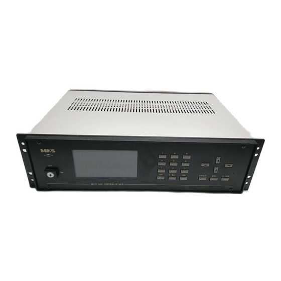
647B 1.6 Drawings 1.6.1 Front Panel A = Key Switch B = Monitor (LCD Display) Figure 2 C = Keyboard Artisan Technology Group - Quality Instrumentation ... Guaranteed | (888) 88-SOURCE | www.artisantg.com... -
Page 9: Rear Panel
647B 1.6.2 Rear Panel 1 = Power Supply Connector Figure 3 8 = Connector PRESSURE for ext. 2 = Voltage Selector Switch pressure controller or transducer 3 = RS 232 Interface (IEEE optional) 9 = Connector ACCESS 4 – 7 = Connectors for MFC’s 10 = Connector RELAYS Artisan Technology Group - Quality Instrumentation ... -
Page 10: Safety Information
647B 1.7 Safety Information 1.7.1 Symbols Used in this Instruction Manual Definitions of WARNING, CAUTION, and ATTENTION messages used throughout the manual. Warning The WARNING sign denotes a hazard. It calls attention to a procedure, practice, condition, or the like, which, if not correctly performed or adhered to, could result in injury to personnel. -
Page 11: Safety Instructions
Cleaning of the device must performed, if it is desconnected from power supply and if the cleaning is performed dry. Warning The device may be opened by MKS service personel only. If the device is open, danger for life (by high voltage) may occur. 1.8 Installation The device must be used in a dry and heated room (see ambient temperature). -
Page 12: Symbols At The Case
1.12 Service In case of problems or failure of the device, please contact your local MKS representative. The last page of this manual contains a list of service and calibration centers. Artisan Technology Group - Quality Instrumentation ... Guaranteed | (888) 88-SOURCE | www.artisantg.com... -
Page 13: Operating Instructions
647B 2. Operating Instructions 2.1 The User Interface The device is operated via menus. A menu consists of submenus, input fields or display fields. Submenus can be reached by typing the number labeling them on the screen or selecting them with the cursor and typing <0>. -
Page 14: The Menu Tree
647B The state of the keyboard is displayed in the “INPUT” field of the status line. DIRECT = input from keyboard enabled = last input was <ON> = last input was <OFF> LOCKED = The keyboard is locked through RS232 or IEEE... -
Page 15: Reset Of System
There is an error in the hardware. If the Start Up problem occurs more than once contact your local MKS service center. Power Up Reset is performed everytime the system is switched on. It resets all data which are... -
Page 16: Functionality
647B 3. Functionality 3.1 The MAIN MENU After turning on the power switch (1) the MAIN MENU is displayed. From this menu the different submenus are accessible. (See also figure 4). 3.2 The USER DISPLAY menu 647B V2.2 0.000 1.750 1.400... -
Page 17: The Extended Display Menu
647B 3.3 The EXTENDED DISPLAY menu 647B V2.2 ACT.FLOW 0.000 1.750 1.400 0.000 SETPOINT 4.500 1.750 1.400 0.728 UNIT SCCM SCCM RANGE FS. 5.000 5.000 1.4000 1.450 USER MODE INDEP. INDEP. INDEP. SLAVE STATUS PRESSURE 0000.0 mbar 00 ERRORS FLOW ON... -
Page 18: The Pressure Control Menu
647B 3.4 The PRESSURE CONTROL menu 647B V2.2 0.000 1.750 1.400 0.000 0.000 0.000 0.000 0.000 GAIN 01.00 PRESSURE UNIT INTEG 02.00 Torr LEAD 00.30 0.3501 SETPOINT MODE 0.467 0.3500 00 ERRORS FLOW ON INPUT DIRECT Figure 8 The PRESSURE CONTROL menu displays the actual flows and the actual pressure with its unit. - Page 19 647B Figure 9 tuning for optimal step response: - gain = 0.6 / K - integral action = 1 * Ts - lead = 0.5 * Tt tuning for optimal disturbance response: - gain = 0.95 / K - integral action = 2.4 * Ts...
-
Page 20: Diagnosis Of System
647B 3.6 Diagnosis of System 3.6.1 The ERROR LISTING menu If the status line indicates the occurrence of errors, details about these errors and the affected channels can be retrieved from the ERROR LISTING menu. 647B V2.2 ERROR LISTING CHANNELS... -
Page 21: The Signals Menu
The display unit is mV. It is possible to enter setpoints in mV directly, if the signal processing is stopped. If you leave the signals menu then signal processing is restarted. This avoids problems concerning general 647B usage. 3.7 Instrument Setup 647B V2.2... -
Page 22: Range Selection
647B 3.7.1 Range Selection 647B V2.2 ACT.FLOW 0.000 1.750 1.400 0.000 UNIT SCCM SCCM RANGE FS. 5.000 5.000 2.000 1.000 STATUS 00 ERRORS FLOW ON INPUT DIRECT Figure 14 The following ranges are available: 1 sccm, 2 sccm, 5 sccm,... -
Page 23: Gas Selection
The 647B automatically calculates the actual range of each mass flow controller (RANGE FS.) from the product GCF x RANGE. E.g. for a flow controller, which is calibrated in 1 slm nitrogen, at a correction factor of 0.72 (methane) the actual flow range (RANGE FS.) displayed in EXTENDED... -
Page 24: Mode Selection
If the setpoint of the master is changed, the 647B also changes the setpoints for the slaves according to this ratio. Additionally in this mode the master channel governs the gas flows of the slave channels. I.e. the setpoints for the slave... - Page 25 Setpoint of MFC = setpoint in EXTENDED MENU * auxiliary input / 5 V 3.7.3.4 PCS Mode In the PRESSURE CONTROL mode (PCS) the 647B serves as the regulating unit for a pressure controller (e.g. type 250). All gas flow channels which are configured in the PCS mode are regulated through the pressure control signal (PCS) according to the ratio of their set points.
-
Page 26: Zero Adjustment
PID option. 3.7.3.6 Test Mode In this mode the 647B generates a test signal, which may be useful for installation procedures. The test signal is a saw tooth beetween zero and 100% with a period of 4 sec. -
Page 27: Trip Limit Supervision
647B 3.7.5 Trip Limit Supervision 647B V2.2 ACT.FLOW 0.000 1.750 1.400 0.000 UNIT SCCM SCCM MIN.LIMIT 3.000 0.750 0.000 0.000 MAX.LIMIT 4.000 0.250 1.400 1.450 SUPERVIS. LIMIT BAND SLEEP SLEEP STATUS 00 ERRORS FLOW ON INPUT DIRECT Figure 18 There are three modes to supervise the process. -
Page 28: Gas Composition
647B Truth Table: Mode Relay # Valve Low limit High limit Relay status SLEEP inactive SLEEP active SLEEP inactive BAND inactive BAND active BAND not exceeded not exceeded inactive BAND exceeded active BAND exceeded active LIMIT not exceeded inactive LIMIT... -
Page 29: System Setup
647B 3.8 System Setup 3.8.1 IEEE 488 Setup 647B V2.2 ADRESS RESPONSE MODE REPEAT INTERFACE STATUS --- --- LCD VIEW ANGLE [°] LCD ON TIME [min] HOST MODE C-MODE RESET EXEC 00 ERRORS FLOW OFF INPUT DIRECT Figure 21 This menu is available instead of RS232 setup, if the IEEE option is installed only. - Page 30 POLLING REPEAT In the QUIET mode, the 647B only responds to a command if data are pending. There is no response if errors occur or if a command results in no data at all. In the POLLING mode each command results an a response. Either data, an error string or an empty acknowledge (i.e.
-
Page 31: Rs232 Setup
LCD ON TIME [min] HOST MODE C-MODE RESET EXEC 00 ERRORS FLOW OFF INPUT DIRECT Figure 22 The 647B implements a standard V24, RS232 interface with standard parameters. Artisan Technology Group - Quality Instrumentation ... Guaranteed | (888) 88-SOURCE | www.artisantg.com... - Page 32 The baudrate defines the transfer speed of characters on the line. The transfer rate of commands and data is determined by this baudrate and by the processing speed of 647B. The first 30 commands will be directed to a buffer at maximum speed, while the transfer of further commands is controlled by a handshake protocol.
- Page 33 A typical error in handling the RS232 line is to plug in the cable, after having switched the device on before. As a result, the 647B works with no handshake although the host computer expects a handshaking. At installation time it may be helpful to check the actual handshake mode.
-
Page 34: System Parameters
SYSTEM SETUP menu. The so called RS232 STATUS display three events on the RS232 line: OE: overrun error: (bytes were lost) Bytes were lost on the input line of 647B. This is typical if the handshake protocol does not work. Check for the correct connection on the line and for fitting handshake protocols. -
Page 35: Pressure Setup
01.00 INTEG.ACT.[s] 02.00 LEAD [s] 00.30 00 ERRORS FLOW OFF INPUT DIRECT Figure 24 The 647B supports several pressure ranges listed below: 1.0000 mTorr, 10.000 mTorr, 100.00 mTorr, 1000.0 mTorr, 1.0000 Torr, 10.000 Torr, 100.00 Torr, 1000.0 Torr, 1.0000 kTorr, 10.000 kTorr,... -
Page 36: Information About The System
In the beginning the C-MODE will be initialized and the device will act like an actual 647B. If a 147B command is used, the 647B will switch to B-MODE (e.g.: MO c 1, PL 1 3). It is also possible to switch to B-MODE through menu SYSTEM SETUP and vice versa. -
Page 37: Command Syntax
647B 4.2 Command Syntax In general all commands are transmitted in ASCII format. Each command string must be terminated by a carriage return and there is no discrimination between upper and lower case letters. In order to improve readability, blanks (20 hex) may be included as delimiters between command, channel number and command parameters, however, this is not necessary. -
Page 38: Table Of Commands
647B 4.3 Table of Commands Select gas menu GM s gas menu X, normal setpoints are used s = 0 gas menu 1-5 s = 1..5 check for gas menu, result: s GM R enter setpoint of a channel FS c xxxx channel c = 1..8... - Page 39 647B MO c m [i] enter mode c = 1..8 channel m = 0 mode = independent m = 1 mode = slave m = 2 mode = extern m = 3 mode = PCS m = 9 mode = test i = 1..8...
- Page 40 (like power up) check for indetification, result: MGC 647B V2.2 – mm dd yyyy month of release day of release yyyy year of release...
- Page 41 A invalid channel number was specified in the command or the channel number is missing. 1 = Unknown Command: A command has been transmitted which is unknown to the 647B. 2 = Syntax error: Only one character has been sent instead of the expected 2 byte command.
- Page 42 647B 4 = Invalid value: The transmitted parameter is outside the parameter range (e.g. 1200 is outside the range of a set point) 5 = Autozero error: There was a trial to set the zero offset of an active channel. Before setting the zero offset, either the channel (OF #) or the gas (OF 0) has to be switched off.
-
Page 43: Application Of The 647B
The mass flow controllers must have a linear DC voltage input and output of 0 – 5 V. MKS mass flow controllers types 0258A/B/C, 0358B/C , 179A can be operated with the connector cables for MKS mass flow controllers types 259, 1259, 2259, 1159, 1179A, 2179A, 1479A, 1359, 1559 and 2159. -
Page 44: Trouble Shooting
647B 5.2 Trouble Shooting Symptom Possible Causes and Remedies 1. No display. Power Failure - Wrong position of voltage selector switch. - Loose mains connection. - No power in the outlet – Fuse is defective – Power supply is broken. -
Page 45: Pin Assignment Of Rear Connectors
647B 6. Pin Assignment of rear connectors 6.1 RS232 connector Sub-D male 9 pol. Figure 26 6.2 IEEE 488 connector DIO 0 DIO 4 DIO 1 DIO 5 DIO 3 DIO 6 DIO 4 DIO 7 ground NRFD ground NDAC... -
Page 46: Relays Connector
647B 6.3 RELAYS connector Two relays are available for each channel. The relay data are: - type of relay: 1 switch with n.o. and n.c. position (SPDT) - max. switch voltage: 100 V - max. power: – max. switch load: 250 mA - max. -
Page 47: Video Connector
647B 6.4 VIDEO connector Sub-D female 9 pol. intensity video signal H-Sync. V-Sync. Figure 29 6.5 MFC connector: CH1 to CH8 Sub-D female 15 pol. chassis flow signal flow feedback /valve close * signal-GND /valve open * signal-GND PGND -15V... -
Page 48: Access Connector
647B 6.6 ACCESS connector Sub-D female 25 pol. reserved chassis external setpoint 1 /valve open 1 external setpoint 2 /valve close 1 external setpoint 3 flow signal 1 external setpoint 4 /valve open 2 +15V /valve close 2 -15V flow signal 2... -
Page 49: Gas Correction Table
647B 7. Gas Correction Table Conversion factors are related to calibration in nitrogen or air. SYMBOL SPECIFIC HEAT, Cp DENSITY CONVERSION cal/g o C g/l @ 0 o C FACTOR Acetylene 0.383 1.171 0.58 - - - 0.240 1.293 1.00 Ammonia 0.492... - Page 50 647B SYMBOL SPECIFIC HEAT, Cp DENSITY CONVERSION cal/g o C g/l @ 0 o C FACTOR Dichlorosilane 0.150 4.506 0.40 1,2-Dichlorotetrafluoroethane 0.160 7.626 0.22 (Freon - 114) 1,1-Difluoroethylene 0.224 2.857 0.43 (Freon - 1132A) 2,2-Dimethylpropane 0.3914 3.219 0.22 Ethane 0.4097 1.342...
- Page 51 647B SYMBOL SPECIFIC HEAT, Cp DENSITY CONVERSION cal/g o C g/l @ 0 o C FACTOR Hydrogen Chloride 0.1912 1.627 1.00 Hydrogen Fluoride 0.3479 0.893 1.00 Isobutylene 0.3701 2.503 0.29 Krypton 0.0593 3.739 1.54 Methane 0.5328 0.715 0.72 Methyl Fluoride 0.3221...
- Page 52 Xenon 0.0378 5.858 1.32 Empirically defined Consult MKS Instruments, Inc. for special applications. NOTE: Standard Pressure is defined as 760 mmHg (1013.25 mbar). Standard Temperature is defined as 0 o C. Note: This table may contain more (or less) gases than that of the unit.
-
Page 53: Index
647B INDEX Actual gas flow 12 independent mode 19 ACTUAL mode 15 INPUT OVERFLOW 15 ASCII format 32 INPUT UNDERFLOW 15 BAND 22 integral 14 baudrate 27 Interface Connections 27 B-MODE 31 interface status 25 C-MODE 31 lead 14 Commands 33... - Page 54 647B rise time 13 TEST 19 RS232 26 test signal 21 TOTAL FLOW 11 RS232 Line Status 29 TRIP HIGH LIMIT 15 RTS, CTS 27 Safety information 5 Trip Limit 22 Setpoints 12 TRIP LOW LIMIT 15 SIGNALS menu 16...
- Page 55 MKS Japan, Inc. Harmonize Building 5-17-13, Narita-Higashi Suginami-Ku, Tokyo 166, Japan Fon: 81-3-3398-8219 CANADA Fax: 81-3-3398-8984 MKS Instruments, Canada Ltd. 30 Concourse Gate KOREA Nepean, Ontario, Canada K2E 7V7 Fon: (613) 723-3386 MKS Korea Co., Ltd. (800) 267-3551 (CAN only) Floor Shin Young Bldg.
Need help?
Do you have a question about the 647B and is the answer not in the manual?
Questions and answers