
Subscribe to Our Youtube Channel
Related Manuals for MKS 649B


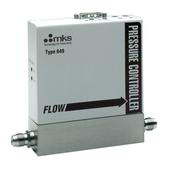
Summary of Contents for MKS 649B
- Page 1 PART REV- C 1023590-001 User Manual MKS TYPE 649B (ROHS COMPLIANT) PRESSURE CONTROLLER WITH INTEGRAL MASS FLOW METER 2 TECH DRIVE ANDOVER, MA 01810 E-MAIL: MKS@MKSINST.COM WWW.MKS.COM (800) 227-8766 OR (978) 645-5500...
- Page 2 All rights reserved. No part of this work may be reproduced or transmitted in any form or by any means, electronic or mechanical, including photocopying and recording, or by any information storage or retrieval system, except as may be expressly permitted in writing by MKS Instruments, Inc. mksinst™ is a trademark of MKS Instruments, Inc.
-
Page 3: Table Of Contents
2.4.1 Símbolos usados en este manual de instrucciones ............21 2.4.2 Símbolos hallados en la unidad ..................22 2.4.3 Procedimientos y precauciones de seguridad ..............23 安全に関する情報 ........................25 2.5.1 本取扱説明書のマーク ....................... 25 2.5.2 本機器のマーク ........................26 3 649B USER MANUAL... - Page 4 4.1.2 Unpacking Checklist ......................36 Interface Cables ........................37 4.2.1 Generic Shielded Cable Description .................. 37 Product Location and Requirements ..................38 Dimensions..........................39 4.4.1 Front and Back Views ......................39 4.4.2 Side View ........................... 41 4 649B USER MANUAL...
- Page 5 How The 649 Pressure Controller Works ................. 48 Flow Measurement Overview ....................49 5.3.1 Flow Path ........................... 49 5.3.2 Measurement Technique ....................49 Tuning the 649B Pressure Controller ..................50 5.4.1 Proportional Term ......................50 5.4.2 Integral Term ........................51 5.4.3 Tuning the 649B Controller ....................51 Priority of Commands ........................
- Page 6 How To Adjust the Pressure Transducer Span ................. 58 How To Zero the Integral Mass Flow Meter ................58 How To Tune the 649B Controller .................... 59 How To Adjust the Trip Point Values ..................59 How To Select the Trip Point Action ..................61 How To Use Trip Points as Error Indicators ................
-
Page 7: List Of Figures And Tables
Table 2: - Initial Configuration ........................46 Table 3: - Highest Pressure for Zero Adjustment of the Pressure Transducer ........58 Table 4: - Valve Orific Sizes ........................73 Table 5 - Valve Orifice Index Number ..................... 74 7 649B USER MANUAL... -
Page 8: Warranty
For the period commencing with the date of shipment of this equipment and ending one (1) year later, MKS will, at its option, either repair or replace any part which is defective in materials or workmanship without charge to the purchaser. The foregoing shall constitute the exclusive and sole remedy of the purchaser for any breach of MKS of this warranty. -
Page 9: Safety
Failure to comply with these precautions or with specific warnings elsewhere in this manual violates safety standards of intended use of the instrument and may impair the protection provided by the equipment. MKS Instruments, Inc. assumes no liability for the customer’s failure to comply with these requirements. -
Page 10: Symbols Found On The Unit
IEC 417, No. 5019 IEC 417, No. 5172-a IEC 617-2, No. 020206 Caution refers to acompanying Caution risk of documents electric shock Caution hot surface ISO 3864, No. B.3 1 ISO 3864, No. B.3 6 IEC 417, No. 5021 10 649B USER MANUAL... -
Page 11: Safety Procedures And Precautions
DO NOT SUBSTITUTE PARTS OR MODIFY INSTRUMENT Do not install substitute parts or perform any unauthorized modification to the instrument. Return the instrument to an MKS Calibration and Service Center for service and repair to ensure that all safety features are maintained. - Page 12 ALLOW PROPER WARM UP TIME FOR TEMPERATURE-CONTROLLED UNITS Temperature-controlled unit will only meet specifications when sufficient time is allowed for the unit to meet, and stabilize at, the designed operating temperature. Do not zero or calibrate the unit until the warmup is complete. 12 649B USER MANUAL...
-
Page 13: Sicherheitshinweise
Gegebenheit aufmerksam, deren unsachgemäße Ausführung bzw. ungenügende Berücksichtigung zu Verletzungen führen kann. Das DANGER-Zeichen weist auf eine unmittelbar gefährliche Situation GEFAHR hin, die, wenn sie nicht vermieden wird, zum Tod oder zu schweren Verletzungen führen wird. 13 649B USER MANUAL... -
Page 14: Erklärung Der Am Gerät Angebrachten Symbole
IEC 417, No.5019 IEC 417, No.5172-a IEC 617-2, No.020206 Warnung vor einer Gefahrenstelle (Achtung, Warnung vor Höhere Temperatur an Dokumentation gefährlicher leicht zugänglichen beachten) elektrischer Spannung Teilen ISO 3864, No.B.3 1 ISO 3864, No.B.3 6 IEC 417, No.5021 14 649B USER MANUAL... -
Page 15: Sicherheitsvorschriften Und Vorsichtsmaßnahmen
Eine Missachtung der Sicherheitsvorschriften und sonstiger Warnhinweise in dieser Betriebsanleitung verletzt die für dieses Gerät und seine Bedienung geltenden Sicherheitsstandards, und kann die Schutzvorrichtungen an diesem Gerät wirkungslos machen. MKS Instruments, Inc. haftet nicht für Missachtung dieser Sicherheitsvorschriften seitens des Kunden. - Page 16 BEI GERÄTEN MIT TEMPERATURKONTROLLE KORREKTE ANWÄRMZEIT EINHALTEN! Temperaturkontrollierte Geräte arbeiten nur dann gemäß ihrer Spezifikation, wenn genügend Zeit zum Erreichen und Stabilisieren der Betriebstemperatur eingeräumt wird. Kalibrierungen und Nulleinstellungen sollten daher nur nach Abschluss des Anwärmvorgangs durchgeführt werden. 16 649B USER MANUAL...
-
Page 17: Informations De Sécurité
Le panneau DANGER indique une situation dangereuse DANGER imminente qui, si elle n’est pas évitée, entraînera la mort ou des blessures graves. 17 649B USER MANUAL... -
Page 18: Symboles Figurant Sur L'unité
IEC 417, No.5019 IEC 417, No.5172-a IEC 617-2, No.020206 Attention : se reporter Attention : risque de Attention : surface à la documentation choc électrique brûlante ISO 3864, No.B.3 1 ISO 3864, No.B.3 6 IEC 417, No.5021 18 649B USER MANUAL... -
Page 19: Mesures De Sécurité Et Précautions
Ne pas installer de pièces de remplacement ni effectuer des modifications non autorisées sur l'appareil. Renvoyer l'appareil à un centre de service et de calibrage MKS pour tout dépannage ou réparation afin de garantir le l'intégrité des dispositifs de sécurité. - Page 20 Les unités à régulation de température sont conformes à leurs spécifications uniquement quand on leur laisse un temps suffisant pour atteindre d'une manière stable la température d'exploitation. Ne pas remettre à zéro ou calibrer l'unité tant que l'échauffement n'est pas terminé. 20 649B USER MANUAL...
-
Page 21: Medidas De Seguridad
La señal de PELIGRO indica una situación inminentemente PELIGRO peligrosa que, si no se evita, resultará en la muerte o lesiones graves. 21 649B USER MANUAL... -
Page 22: Símbolos Hallados En La Unidad
Si el cliente no cumple dichas precauciones y advertencias, MKS Instruments, Inc. no asume responsabilidad legal alguna. 22 649B USER MANUAL... - Page 23 No instale piezas que no sean originales ni modifique el instrumento sin autorización. Para asegurar el correcto funcionamiento de todos los dispositivos de seguridad, envíe el instrumento al Centro de servicio y calibración de MKS toda vez que sea necesario repararlo o efectuar tareas de mantenimiento.
- Page 24 No calibre la unidad y no la ponga en cero hasta que finalice el procedimiento de calentamiento. 24 649B USER MANUAL...
-
Page 25: 安全に関する情報
TYPE OF USER MANUAL PART REV- C 1023590-001 マスフロー機器の安全に関する情報 2.5.1 この取扱説明書で使用されている記号 本マニュアルでは警告、注意、ポイントのマークを用いて重要な事項を記載しています。 ポイント この表示は手順や使用方法、条件などに関する重要な情報が記載されている ことを示 しています。必ずお読みください。 この表示を無視して誤った取り扱い (手順や使用方法など) をすると、 製品 注意 が損傷する可能性が想定される内容を示しています。必ずお読みください。 この表示を無視して誤った取り扱い (手順や使用方法、条件など) をすると 警告 、人が重傷を負う可能性が想定される内容を示しています。必ずお読みくだ さい。 危険 危険記号は、回避しないと死亡または重傷を負う差し迫った危険な状況を示 します。 25 649B USER MANUAL... -
Page 26: 本機器のマーク
クラス 2 機器 直流と交流 三相交流 IEC 417, No. 5019 IEC 417, No. 5172-a IEC 617-2, No. 020206 注意 (表面が熱くなっ 注意 (付属書を参照) 注意 (感電の危険あり) ています) ISO 3864, No. B.3 1 ISO 3864, No. B.3 6 IEC 417, No. 5021 26 649B USER MANUAL... -
Page 27: 安全対策について
TYPE OF USER MANUAL PART REV- C 1023590-001 2.5.3 安全対策について 本機器を使用する際は、必ず以下の安全対策を守ってください。これらの安全対策や本マニュアルの 警告を無視すると、機器本来の用途の安全基準を侵害することになり、機器が提供する保護機能が損 なわれる可能性があります。MKS Instruments, Inc. は、顧客側の安全対策の不履行に対しては一切責 任を負いかねます。 勝⼿に部品を変えたり、本体を改造しないこと 本機器に代⽤部品を使⽤したり、不正な改造を加えないでください。すべての安全システムを正しく 機能させるための修理やメンテナンスが必要な場合は、本機器を MKS Calibration and Service Center まで戻してください。 修理は必ず専⾨の修理サービスを利⽤すること オペレータは絶対に本機器を分解しないでください。部品の交換や内部の調整は必ず専⾨の修理サー ビスを利⽤してください。 電流が通じている回路から切断すること 電源ケーブルを接続したままで部品を交換しないでください。特定の状況では、電源ケーブルを取り 外した状態でも危険な電圧が残っている場合があります。感電などの事故を防ぐため、回路に触れる 前に必ず電源から切断し、放電してください。 危険な材料を使⽤する場合は慎重に機器を使⽤すること 危険な材料を使⽤する場合は、使⽤者は各⾃の責任の元で適切な安全対策を講じてください。必要に 応じて本機器を浄化してください。また、使⽤する材料に対するシーリング材の耐久性を確認してく ださい。 機器を浄化すること 本機器を取り付けた後やシステムから取り外す前に、きれいな乾燥ガスで本機器を浄化し、使⽤した 材料を完全に取り除いてください。... - Page 28 TYPE OF USER MANUAL PART REV- C 1023590-001 爆発の危険性のある環境で機器を使⽤しないこと 爆発が起きるのを防ぐため、本機器を爆発の危険性のある環境で使⽤しないでください。ただし、そ のような環境での使⽤が特別に保証されている場合は除きます。 適切な⾦具類を使⽤し、⼿順に従って⾦具の締めを⾏うこと ⾦具類は本機器の仕様と⼀致し、機器本来の⽤途に適合したものである必要があります。⾦具類の取 り付けや締めは、製造業者の指⽰に従ってください。 液体の漏れがないよう接続箇所を確認すること 本機器を設定する前に、すべての配管の接続を慎重に確認し、液体が漏れないようにしてください。 マスフロー機器の安全に関する情報 安全なインレット圧⼒で使⽤すること 定格の最⼤圧⼒を超える圧⼒の下で本機器を絶対に使⽤しないでください (最⼤許容圧⼒については仕 様書を参照)。 適切なバーストディスクを取り付けること 圧⼒のかかったガスを使⽤する場合は、万⼀システムが爆発した場合にシステムの圧⼒が上昇するの を防ぐため、真空システムに適切なバーストディスクを取り付けてください。 本機器に異物やゴミが混⼊しないようにすること 本機器の使⽤前または使⽤中に、ほこりやゴミ、繊維、ガラスの破⽚、⾦属⽚などの異物やゴミが混 ⼊しないようにしてください。本機器が損傷する可能性があります。 温度調整された機器を⼗分に温めてから使⽤すること 温度調整された機器が適切な作動温度にならないうちに使⽤すると、仕様通りの動作をしないことが あります。本機器が⼗分に温まるまでは⽬盛りをゼロに合わせたり、較正しないでください 28 649B USER MANUAL...
-
Page 29: 장치 안전 정보
경고 표시는 위험을 나타냅니다. 이 표시는 올바르게 수행되거나 지켜지지 않을 경우, 사람에게 상해를 입힐 수 있는 절차, 수행지침, 상태 또는 이와 유사한 상황들에 대한 주의를 환기시킵니다. 그만큼 위험 표시 피하지 않을 경우 사망이나 심각한 부상을 초래할 수있는 위험 임박한 위험한 상황을 나타냅니다. 29 649B USER MANUAL... -
Page 30: 장치에 표시된 기호들
IEC 417, No. 5019 IEC 417, No. 5172-a IEC 617-2, No. 020206 주의 (동봉 문서 참조) 주의, 감전 위험 주의, 표면이 뜨거움 ISO 3864, No. B.3 1 ISO 3864, No. B.3 6 IEC 417, No. 5021 30 649B USER MANUAL... -
Page 31: 안전 절차 및 예방조치
준수하지 않거나 본 매뉴얼의 다른 부분에 있는 특정 경고를 준수하지 않을 경우, 기계 사용 목적의 안전 기준을 위반하는 것이 되며, 장비가 제공하는 보호기능을 손상시킬 수 있습니다. MKS Instruments, Inc.는 고객이 본 요건을 준수하지 않는 경우에 대해서는 어떠한 책임도 지지 않습니다. - Page 32 유리 조각, 금속 조각과 같은 오염 물질은 영구적으로 장치를 손상시킬 수 있습니다. 온도 제어 장치의 경우 알맞은 시동 시간을 두십시오 온도 제어 장치는 장치가 설계 작동 온도와 일치하고 이 온도에서 안정화될 수 있도록 충분한 시간을 허용해야만 사양에 맞게 작동합니다. 시동이 완료될 때까지 장치를 영점 설정하거나 보정하지 마십시오. 32 649B USER MANUAL...
-
Page 33: Chapter 3 General Information
One Type “D” connector, located on the top of the unit, accepts the input power, and has both the pressure (input and output) and flow (output) signals. You can connect the 649B controller to an MKS Type 247 or 246 Mass Flow Controller Power Supply/Readout or a Type 647 Mass Flow and Pressure Programmer/Display unit. -
Page 34: Cleanliness Features
In addition, observe and obey all WARNING and CAUTION notes provided throughout the manual. Chapter One, Warranty Information, explains the warranty policies for MKS Instruments and the 649B pressure controller. Chapter Two, Safety, is the most important chapter, and explains the safety measures and procedures that must be followed when using this instrument. -
Page 35: Manual Conventions
The RMA Number expedites handling and ensures proper servicing of your instrument. Please refer to the inside of the back cover of this manual for a list of MKS Calibration and Service Centers. All returns to MKS Instruments must be free of harmful, corrosive, WARNING radioactive, or toxic materials. -
Page 36: Chapter 4 Installation
If you find any damage, notify your carrier and MKS immediately. If it is necessary to return the unit to MKS, obtain an RMA Number (Return Material Authorization Number) from the MKS Service Center before shipping. -
Page 37: Interface Cables
1023590-001 Interface Cables Use a CB649S-1-Mx or CB649-1-Mx cable (where x indicates code for the length) to connect the 649B controller to an MKS Type 247 or 246 Mass Flow Controller Power Supply/Readout or a Type 647 Mass Flow and Pressure Programmer/Display unit. The standard cable, CB649-1-M1 is 10 feet in length. -
Page 38: Product Location And Requirements
Use high purity gas and filters in line upstream of the controller • • Mount the 649B controller in an upright position, if possible, although any mounting orientation is satisfactory Refer to Installing the Unit, page 43, for more information. -
Page 39: Dimensions
Front and Back Views The front of the 649B controller has an arrow to indicate the direction of gas flow through the unit. The back of the unit has the serial number tag and the pinout for the 15-pin Type “D” connector. - Page 40 TYPE OF USER MANUAL PART REV- C 1023590-001 Type 649 5.50 5.29 (139.8) (134.4) 4-VCR: 6.66 (169.2) 8-VCR: 7.11 (180.6) Figure 1 - Front View Figure 2 - Rear View 40 649B USER MANUAL...
-
Page 41: Side View
M FM Adjust Zero Sp an 0.50 (12.7) 0.74 (18.8) 1.48 (37.6) Figure 3 - Side View 4.4.3 Bottom View The bottom of the 649B controller has has mounting holes for mounting the unit, if desired. 41 649B USER MANUAL... -
Page 42: Dimensions
4.5.2 Mounting Hardware The 649B controller has two mounting holes located on the bottom or base of the unit. Use #8-32 UNC-2B hardware to mount the unit. Refer to Figure 4 shows the location and dimension of the mounting holes. -
Page 43: Installing The Unit
649 unit controls the pressure downstream of the 649B controller itself. The gas enters the 649B controller on the flow meter side and flows in the direction of the flow arrow on the front of the unit. The outlet of the instrument is the controlled pressure port. - Page 44 Pressure Signal Output (Pin 2) The 649B controller allows you to access the pressure signal from the pressure transducer, correct it in some way, and re-introduce it into pin 10 of the I/O connector to be used as the input signal in closed- loop control.
- Page 45 Use pin 10 to introduce another signal, such as a zero corrected pressure signal, into the control circuitry of the 649B controller. When a signal equal to or greater than 0.25V is introduced on pin 10, it overrides the Pressure Output signal (pin 2) until the signal on pin 10 drops below -0.8V.
-
Page 46: Initial Configuration
P Term Position 0 (8 repeats setting 0; and 9 repeats setting 1) I Term Position 0 10 settings, 0 through 9 * Input must match the pressure output signal range Table 2 - Initial Configuration 46 649B USER MANUAL... -
Page 47: Chapter 5 Overview
Pressure Control Range The 649B controller can control pressure over a range of 5 to 100% of full scale. This means that a 649B controller with a 100 Torr [13.3 kPa] pressure transducer can control pressure from 50 torr [6.66 kPa] to 1000 torr [133 kPa], whereas a unit with a 100 torr [13.3 kPa] pressure transducer can control... -
Page 48: A Typical Control System
The 649B controller compares the pressure reading to the setpoint, and positions the valve to maintain, or achieve, the setpoint pressure. The controller functions as a PI (Proportional-Integral) controller. Both the Proportional (P) term, and the Integral (I) term have adjustable dials on the top of the 649B controller. -
Page 49: Flow Measurement Overview
Figure 5, page 43, shows the correct location for the 649B controller. When the actual pressure reading is less than the setpoint value, the 649B controller opens the valve to increase the amount of gas entering the system. As the valve opens, gas enters the pressure system, so the pressure rises to meet the setpoint value. -
Page 50: Tuning The 649B Pressure Controller
Tuning optimizes the way the 649 unit controls your system. The Proportional (P) and Integral (I) terms adjust the response of the 649B controller. The controller responds to changes in either the pressure of the system or the value of the setpoint. -
Page 51: Integral Term
5.4.3 Tuning the 649B controller Tuning the 649B controller involves adjusting the Proportional and Integral terms to optimize the response of the controller in your system. Since every system is different, the optimum settings for the P term and I term will vary. Also, the response of the system to increasing and decreasing pressures may vary. - Page 52 REV- C 1023590-001 The following graphs show the response of the 649B controller to changes in the setpoint. The setpoint changed from 4 torr [533 Pa] (2 Volts) to 6 torr [800 Pa] (3 Volts), and back again. The following three graphs were generated on a system consisting of a...
- Page 53 Figure 12 - Controller Response with Increased I Term The response of the controller is quick, yet no overshoot occurs. This combination of P term and I term yields the best control for our example system. 53 649B USER MANUAL...
-
Page 54: Priority Of Commands
(pin 2) or any signal on the Optional Input pin (pin 10) to the setpoint. The 649B controller positions its valve to achieve or maintain the setpoint pressure (or other variable if the Optional Input is used) in the system. Closed-loop control mode has the lowest priority. -
Page 55: Trip Points
1023590-001 Trip Points The 649B controller provides two trip points (Trip Point A and Trip Point B). Each trip point operates independently and controls an open collector output that can be connected to an external relay. Each trip point has an adjustment pot, a status LED, and a test jack. Refer to Figure 6. for the location of the trip point adjustment pots and LEDs. -
Page 56: Applications With A Large Differential Pressure
A normally closed valve may be unable to open. Labels The 649B controller carries a serial number label which identifies the serial number, model number, calibration gas, full scale flow rate, and pressure range. It also displays the CE Mark which indicates compliance with European directives. -
Page 57: Chapter 6 Operation
Check the pressure transducer zero before operating the unit initially and then periodically as required. The zero can be set (or reset) by adjusting the zero potentiometer located on the top cover of the 649B controller or, on the front panel of an MKS Power Supply/Readout if you are using one. -
Page 58: How To Adjust The Pressure Transducer Span
Only adjust the pot in conjunction with a calibration transfer standard. Do not adjust the span SPAN setting if a calibration transfer standard is not available. Instead, contact an MKS Service Center for calibration. How to Zero the Integral Mass Flow Meter Ensure that no gas flow is entering the 649B controller. -
Page 59: How To Tune The 649B Controller
How To Tune the 649B controller You may need to tune the 649B controller to optimize how it controls your system. Tuning consists of varying the P (Proportional) and I (Integral) parameters to achieve the fastest, smoothest response to changes in the setpoint value. - Page 60 Stop the gas flow through the 649B controller. 2. Remove any leads or wires attached to the connector on the 649B controller. 3. Use a 4.8 mm hex wrench (or open-ended wrench) to remove the hex nuts on each side of the I/O connector.
-
Page 61: How To Select The Trip Point Action
Equipment required: 4.8 mm hex or open-ended wrench The 649B controller is initially configured with TP A set to trip high (it is on when the pressure is above the trip point pressure) and TP B set to trip low (it is on when the pressure is below the trip point pressure). -
Page 62: How To Use Trip Points As Error Indicators
47.5 to 52.5 torr [6.333 to 6.999 kPa]. The 649B controller is initially configured with TP A on above the trip point and TP B on below the trip point. If you have not changed the action of either trip point, you may follow the steps below. If you have changed the action of the trip points, you need to reset them back to the initial configuration for this example. - Page 63 Should the pressure deviate from this range the appropriate trip point will turn on and its LED will illuminate. Trip Point A will turn on when the pressure exceeds 52.5 torr [6.999 kPa] and Trip Point B will turn on when the pressure falls below 47.5 torr [6.333 kPa]. 63 649B USER MANUAL...
-
Page 64: How To Change The Pressure Output Signal Range
6. Position the controller with the front side facing you and pull up on the enclosure to remove The MKS logo is displayed on the front of the unit. The board assembly will be visible, with the Transducer board facing you. The Control board is connected to the back of the Transducer board. - Page 65 TYPE OF USER MANUAL PART REV- C 1023590-001 11. Slide the enclosure cover over the unit. 12. Attach the hex nuts to the I/O connector and Philip screws removed in step 3. 13. Reconnect the leads and wires. 65 649B USER MANUAL...
-
Page 66: Chapter 7 Maintenance
It is also recommended that the instrument be recalibrated annually if no other time interval has been specifically established. Refer to the inside of the back cover of this instruction manual for a complete list of MKS Calibration and Service centers. 66 649B USER MANUAL... -
Page 67: Appendix
5 minutes Includes controller error, linearity, hysteresis, and repeatability. Includes the controller error only. An overall metal braided shielded cable, properly grounded at both ends, is required during use. Consistent with the overpressure limit of the transducer. 67 649B USER MANUAL... - Page 68 Seat Material Kel-F , Viton , metal or Kalrez Surface Finish <0.4 m, Ra, electropolished Weight 1.6 kg Wetted Materials (excluding valve seat) 316L VIM/VAR stainless steel, Inconel , Nickel, Elgiloy 68 649B USER MANUAL...
- Page 69 Status LEDs Green when the transistor is on Settings 0 to 5 Volts corresponds to 1 to 100 % full scale Due to continuing research and development activities, these product specifications are subject to change without notice. 69 649B USER MANUAL...
-
Page 70: Appendix B: Model Code Explanation
The options of your 649 unit are identified in the model code when you order the unit. The model code is identified as follows: 649BGGGXXXYYYZAB where: 649B Type Number Gas Code Pressure Range Flow Rate Valve Orifice Size Valve Plug Seat Material Fittings 70 649B USER MANUAL... - Page 71 PART REV- C 1023590-001 Type Number (649B) This designates the model number of the instrument. 649B designates the ROHS compliant version of the 649B product. Gas Code (GGG) The gas code is indicated by a three digit code. Gas Code...
- Page 72 The valve plug seat material is specified by a single letter code. Valve Plug Seat Material Ordering Code Metal Viton Kel-F Kalrez Fittings (B) The choice of fittings is indicated by a single letter code. Fittings Ordering Code Cajon 4-VCR, male Cajon 8-VCR, male 72 649B USER MANUAL...
-
Page 73: Appendix C: Valve Orifice Selection
Appendix C: Valve Orifice Selection General Information The 649B controller is available in four valve orifice sizes. You should confirm that the valve orifice in your 649B controller is the correct size for your application before you install it into your system. The orifice is not adjustable and is only replaceable at the factory. - Page 74 TYPE OF USER MANUAL PART REV- C 1023590-001 How To Verify the Orifice Selection Figure 15 - Valve Orifice Index Number Table 5 - Valve Orifice Index Number 74 649B USER MANUAL...
- Page 75 1. On the Index Number Table 5, choose your inlet pressure from the column of pressures on the left– the pressure that will be applied to the inlet of your 649B. (Note that the values are absolute pressure.) Next, from the row of pressures at the top of that table, select your differential (delta) pressure –...
-
Page 76: Index
Flow range, 47 Process control, 55 Proportional control, 48, 50-51, 59, 67 I/O connector, 43-44 Inlet pressure, 42, 56 Range, 47, 64, 67-68, 70, 73 Installation, 36 Returning the product, 35-36 Integral control, 48, 50-51, 59, 67 76 649B USER MANUAL... - Page 77 Valve test point, 44 environmental, 69 physical, 68 Zero trip points, 69 mass flow meter, 58-59 transducer, 57 Transducer board, 55, 61-62 Trip point action, 61 Trip point values, 60 Trip points, 55, 59-62, 69 Tuning, 48, 50-53, 59 77 649B USER MANUAL...
Need help?
Do you have a question about the 649B and is the answer not in the manual?
Questions and answers