Table of Contents
Advertisement
Advertisement
Table of Contents

Related Manuals for MKS 640A/641A


Summary of Contents for MKS 640A/641A
- Page 1 Artisan Technology Group is your source for quality new and certified-used/pre-owned equipment SERVICE CENTER REPAIRS WE BUY USED EQUIPMENT • FAST SHIPPING AND DELIVERY Experienced engineers and technicians on staff Sell your excess, underutilized, and idle used equipment at our full-service, in-house repair center We also offer credit for buy-backs and trade-ins •...
- Page 2 116669-P1 Rev C, 12/99 Instruction Manual MKS Type 640A/641A Pressure Controller Six Shattuck Road Fax: (978) 975-0093 Andover, MA 01810-2449 E-mail: mks@mksinst.com (800) 227-8766 or (978) 975-2350 Web site: http://www.mksinst.com...
- Page 3 MKS sales representative or distributor from which the equipment was purchased or, in the case of a direct purchase from MKS, with the MKS home office in Andover, Massachusetts, USA.
- Page 4 116669-P1 Rev C, 12/99 MKS Type 640A/641A Pressure Controller...
- Page 5 All rights reserved. No part of this work may be reproduced or transmitted in any form or by any means, electronic or mechanical, including photocopying and recording, or by any information storage or retrieval system, except as may be expressly permitted in writing by MKS Instruments, Inc.
-
Page 6: Table Of Contents
Table of Contents Table of Contents Pressure Transducer Safety Information.................. 1 Symbols Used in This Instruction Manual..............1 Symbols Found on the Unit ..................2 Safety Procedures and Precautions ................3 Chapter One: General Information..................5 Introduction ....................... 5 How This Manual is Organized.................. 6 Manual Conventions .................. - Page 7 Table of Contents Initial Configuration....................31 Chapter Three: Overview .......................33 General Information ....................33 Pressure Control Range..................33 A Typical Control System................34 How The 640 Series Pressure Controller Works ............35 Tuning the 640 Series Pressure Controller ..............36 Proportional Term..................36 Integral Term ....................37 Tuning the 640 Controller................38 Priority of Commands ....................40 Trip Points .........................41 Action of the Trip Points................41...
- Page 8 Table of Contents General Information....................57 Checking the Orifice Size................57 How To Verify the Orifice Selection................58 Using Different Gases ................... 60 Appendix C: Gas Density Table .................... 63 Appendix D: Model Code Explanation .................. 67 Model Code Description .................... 67 Index............................
- Page 9 Table of Contents...
- Page 10 List of Figures List of Figures Figure 1: Downstream Pressure Control ................16 Figure 2: Upstream Pressure Control ..................16 Figure 7: Front and Back Views of the Side Port 640 Series Controller ......... 17 Figure 8: Side View of the 640 Series Controller..............18 Figure 3: Top View of the Down Port Type 640 Controller ...........
- Page 11 List of Figures viii...
- Page 12 List of Tables List of Tables Table 1: Definition of Symbols Found on the Unit ..............2 Table 2: Interface Cables ......................11 Table 7: I/O Connector Pinout....................13 Table 3: Fitting Dimension.......................17 Table 4: SEMI Specifications for Down Port Fitting Options ...........22 Table 5: SEMI 2787.1 C-Seal Retainer (EG&G Part Numbers) ..........23 Table 6: 0.445 Inch Diameter C-Seal Retainer .................23 Table 8: Initial Configuration ....................31...
- Page 13 List of Tables...
-
Page 14: Pressure Transducer Safety Information
Pressure Transducer Safety Information Symbols Used in This Instruction Manual Pressure Transducer Safety Information Symbols Used in This Instruction Manual Definitions of WARNING, CAUTION, and NOTE messages used throughout the manual. Warning The WARNING sign denotes a hazard to personnel. It calls attention to a procedure, practice, condition, or the like, which, if not correctly performed or adhered to, could result in injury to personnel. -
Page 15: Symbols Found On The Unit
Symbols Found on the Unit Pressure Transducer Safety Information Symbols Found on the Unit The following table describes symbols that may be found on the unit. Definition of Symbols Found on the Unit Protective earth (ground) Off (Supply) Earth (ground) On (Supply) IEC 417, No.5019 IEC 417, No.5017... -
Page 16: Safety Procedures And Precautions
DO NOT SUBSTITUTE PARTS OR MODIFY INSTRUMENT Do not install substitute parts or perform any unauthorized modification to the instrument. Return the instrument to an MKS Calibration and Service Center for service and repair to ensure that all safety features are maintained. - Page 17 Safety Procedures and Precautions Pressure Transducer Safety Information CHECK FOR LEAK-TIGHT FITTINGS Carefully check all vacuum component connections to ensure leak-tight installation. OPERATE AT SAFE INLET PRESSURES Never operate at pressures higher than the rated maximum pressure (refer to the product specifications for the maximum allowable pressure).
-
Page 18: Chapter One: General Information
Chapter One: General Information Introduction Chapter One: General Information Introduction The 640A Series Pressure Controllers include the Type 640 absolute pressure controller and the Type 641 gage pressure controller. The 640 Series Controllers consist of a Baratron ® capacitance manometer (either absolute or gage pressure), a normally closed proportional control valve, and closed-loop control electronics. -
Page 19: How This Manual Is Organized
How This Manual is Organized Chapter One: General Information How This Manual is Organized This manual provides instructions on how to set up and install a 640 Series unit. Before installing your 640 Series unit in a system and/or operating it, familiarize yourself with all precautionary notes in the Safety Messages and Procedures section at the front of this manual. -
Page 20: Customer Support
Calibration and Service Center before shipping. The ERA Number expedites handling and ensures proper servicing of your instrument. Please refer to the inside of the back cover of this manual for a list of MKS Calibration and Service Centers. Warning All returns to MKS Instruments must be free of harmful, corrosive, radioactive, and toxic materials. - Page 21 Customer Support Chapter One: General Information This page intentionally left blank.
-
Page 22: Chapter Two: Installation
Chapter Two: Installation How To Unpack the 640 Series Controller MKS has carefully packed the 640 Series unit so that it will reach you in perfect operating order. Upon receiving the unit, however, you should check for defects, cracks, broken connectors, and the like, to be certain that damage has not occurred during shipment. -
Page 23: Product Location And Requirements
Warning Follow your corporate policy for handling toxic or hazardous gases. Your corporate policy on handling these gases supersedes the instructions in this manual. MKS assumes no liability for the safe handling of such materials. • Install the 640 Series controller in a “flowing” system where gas is continually added and evacuated. -
Page 24: Interface Cables
January 1, 1997, some products shipped to the European Community must also comply with the Product Safety Directive 92/59/EEC and Low Voltage Directive 73/23/EEC, which cover general safety practices for design and workmanship. MKS products that meet these requirements are identified by application of the CE Mark. -
Page 25: Generic Shielded Cable Description
Chapter Two: Installation Generic Shielded Cable Description MKS offers a full line of cables for all MKS equipment. Should you choose to manufacture your own cables, follow the guidelines listed below: 1. The cable must have an overall metal braided shield, covering all wires. Neither aluminum foil nor spiral shielding will be as effective;... -
Page 26: The I/O Connector
Chapter Two: Installation The I/O Connector The I/O Connector The Type 640 Series controller has one 15-pin, male Type “D” connector that provides the pressure output, set point input, and trip point output signals. I/O Connector Pinout Pin # Assignment Valve Test Point Pressure Signal Output Valve Close... - Page 27 The I/O Connector Chapter Two: Installation Set Point Input (Pin 8) The set point input signal can be a 0 to 5 Volt (factory setting) or 0 to 10 Volt signal. The range of the set point input signal must match the range of the pressure output signal. The 640 controller is initially configured for a 0 to 5 Volt pressure output signal.
-
Page 28: Gas Pressure And Control
Connect the port labeled “Controlled Pressure Port” to the system whose pressure you need to control. Note MKS defines “upstream” and “downstream” control by the location of the controlled volume relative to the 640 Series Pressure Controller. Downstream Pressure Control... -
Page 29: Figure 1: Downstream Pressure Control
Gas Pressure and Control Chapter Two: Installation Downstream Pressure Control Controlled Volume Gas Flow Figure 1: Downstream Pressure Control The 640 Series controllers are shipped from the factory configured for downstream pressure control. Refer to Table 8, page 31, for the initial configuration of the unit. Upstream Pressure Control Upstream pressure control occurs when the 640 Series controller is positioned after the controlled pressure volume in the gas flow path, so that the controlled volume is upstream of the... -
Page 30: Dimensions
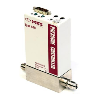
Chapter Two: Installation Dimensions Dimensions Note All dimensions are listed in inches with millimeters referenced in parentheses. Side Port Version Front and Back Views The front of the unit has a “Controlled Pressure Port” label to indicate the transducer port. The opposite port houses the control valve. -
Page 31: Figure 8: Side View Of The 640 Series Controller
Dimensions Chapter Two: Installation Side View Pressure controllers have trip point test jacks located on the left, or valve, side of the unit. The test jacks enable you to measure the voltage value of each trip point while adjusting it via pots on the top of the unit. -
Page 32: Down Port Version
Chapter Two: Installation Dimensions Down Port Version Interface Connector Figure 5: Top View of the Down Port Type 640 Controller 5.522 (140.26) 0.020 0.985 +0.020 (0.51) (25.02 +0.51) Inlet Outlet 1.476 +0.025 (37.49 +0.63) Figure 6: Front and Side View of the Down Port Type 640... -
Page 33: Figure 5: Bottom View Of The Down Port 640
Dimensions Chapter Two: Installation 0.591+0.005 3.622+0.015 (15 +0.12) (92+0.38) 1.181+0.005 (30 +0.12) 4.14+0.02 (105.0+0.5) Figure 7: Bottom View of the Down Port 640 C-Seal C-Seal (SEMI 2787.1) (0.445 in. diameter) 0.445 dia. x 0.020 dp 0.300 dia x 0.024 dp. (11.3 x 0.508 dp) (7.62 x 0.610 dp) 0.221 dia. -
Page 34: Side Port Controller Mounting Instructions
Chapter Two: Installation Side Port Controller Mounting Instructions Side Port Controller Mounting Instructions Fittings The 640 Series pressure controller is available with the following fittings: • Cajon 4-VCR male compatible • Cajon 8-VCR male compatible • ¼” Swagelok compatible Mounting Hardware The Side Port 640 Series controller has four threaded mounting holes on the bottom or base of the unit. -
Page 35: Down Port Controller Mounting Instructions
Down Port Controller Mounting Instructions Chapter Two: Installation Down Port Controller Mounting Instructions Refer to SEMI specification 2787.x for specific information on each fitting, as shown in Table 5. SEMI Specifications for Down Port Fitting Options Fitting Model Code SEMI Designation Specification C-Seal... -
Page 36: How To Connect The C-Seal Fittings
Chapter Two: Installation Down Port Controller Mounting Instructions How To Connect the C-Seal Fittings Note This section covers the mounting instructions for both the SEMI 2787.1 compliant and 0.445 inch diameter C-seals. 1. Select the retainer and screws appropriate for the type of C-seal. There are two types of seal assemblies available: •... -
Page 37: Figure 10: Exploded View Of The C-Seal Components
Down Port Controller Mounting Instructions Chapter Two: Installation 4. Clean the sealing surfaces of the MFC and substrate using a clean room swab dampened with a solvent such as isopropyl alcohol. Wipe the surfaces in a circular pattern with light pressure. Blow clean the surfaces with filtered nitrogen. Note Clean all re-used sealing surfaces prior to resealing. - Page 38 Chapter Two: Installation Down Port Controller Mounting Instructions 9. Place the controller and seal assembly onto the substrate; make sure to align the seals and screws properly. 10. Finger-tighten the screws evenly. Ensure that the controller is level or parallel to the substrate.
-
Page 39: How To Connect The W-Seal (Semi 2878.3) Fittings
Down Port Controller Mounting Instructions Chapter Two: Installation How To Connect the W-Seal (SEMI 2878.3) Fittings Note The gaskets used in the W-seal are also referred to as IGS (Integrated Gas Systems) gaskets. Replacement gaskets (part number UGF-6.35G) are available from Fujikin of America, Inc. 1. - Page 40 Chapter Two: Installation Down Port Controller Mounting Instructions 5. Align the controller with the substrate and set the controller in place. 6. Finger-tighten the four (4) M5 x 30 mm long socket head cap screws evenly. Ensure that the controller is level or parallel to the substrate. 7.
-
Page 41: How To Connect The Z-Seal (Semi 2878.2) Fittings
Down Port Controller Mounting Instructions Chapter Two: Installation How To Connect the Z-Seal (SEMI 2878.2) Fittings Note A Seal Kit, containing screws, keepers, and Z-seal gaskets, is available from Unit Instruments (part number 750-001-A0522). Pre-assemble the Z-Seal End Fitting 1. Remove the protective packaging from the controller. 2. - Page 42 Chapter Two: Installation Down Port Controller Mounting Instructions 4. Insert the 10-32 UNF x 1.25 long socket head mounting screws into the split rings from below. 5. Use a clean room foam swab to wipe the Z-seal are clean. Note The Z-seal edge is so sharp it will cut a normal woven wiper and create lint.
- Page 43 Down Port Controller Mounting Instructions Chapter Two: Installation 5. Tighten the mounting screws with increments of approximately turn each, using a inch hex driver. Do not make a “criss-cross” pattern; instead close the fitting to substrate gap about halfway on one fitting then on the other. Finish the seal on the first fitting followed by the second.
-
Page 44: Initial Configuration
Chapter Two: Installation Initial Configuration Initial Configuration The 640 Series Pressure Controller is shipped from the factory with the configuration listed in Table 8. Initial Configuration Feature Setting Options Pressure Control Downstream Upstream Set Point Input* 0 to 5 V 0 to 10 V Pressure Output 0 to 5 V... - Page 45 Initial Configuration Chapter Two: Installation This page intentionally left blank.
-
Page 46: Chapter Three: Overview
Chapter Three: Overview General Information Chapter Three: Overview General Information Figure 13 shows the top view of the 640 Series Pressure Controller. The user adjustable controls for zero, span, the P term, the I term, and the trip points are located on the top of the controller. The trip point settings can be measured through two test jacks, located on the side of unit, as shown in Figure 4, page 18. -
Page 47: A Typical Control System
Pressure system (whose pressure is being controlled) The 640 Series Pressure Controller provides the first three components. • The pressure transducer is an MKS Baratron capacitance manometer. • The 640 Series unit contains the electronics necessary for pressure control. •... -
Page 48: How The 640 Series Pressure Controller Works
Chapter Three: Overview How The 640 Series Pressure Controller Works How The 640 Series Pressure Controller Works The 640 Series controller compares the pressure reading to the set point, and positions the valve to maintain, or achieve, the set point pressure. The controller functions as a PI (Proportional- Integral) controller. -
Page 49: Tuning The 640 Series Pressure Controller
Tuning the 640 Series Pressure Controller Chapter Three: Overview Tuning the 640 Series Pressure Controller Tuning optimizes the way the 640 Series unit controls your system. The Proportional (P) and Integral (I) terms adjust the response of the 640 Series controller. The controller responds to changes in either the pressure of the system or the value of the set point. -
Page 50: Integral Term
Chapter Three: Overview Tuning the 640 Series Pressure Controller Integral Term The action of the Integral (I) term creates a valve drive signal that is proportional to the magnitude and sign of the area under the error signal curve (error signal with respect to time). Therefore, as time passes, the integral term acts to position the valve to reduce the error signal to zero. -
Page 51: Tuning The 640 Controller
Tuning the 640 Series Pressure Controller Chapter Three: Overview Tuning the 640 Controller Tuning the 640 controller involves adjusting the Proportional and Integral terms to optimize the response of the controller in your system. Since every system is different, the optimum settings for the P term and I term will vary. -
Page 52: Figure 18: Controller Response With Increased P Term
Chapter Three: Overview Tuning the 640 Series Pressure Controller Controller Response with Increased P Term Increasing the P term to 1 while holding the I term at 0 yields: Settling Time Settling Time P = 1 Set Point I = 0 Signal Time Figure 18: Controller Response with Increased P Term... -
Page 53: Priority Of Commands
Priority of Commands Chapter Three: Overview Priority of Commands The 640 Series controller has an established hierarchy that it uses to determine which commands take precedence. The commands and operating modes are listed according to the order of priority (from highest to lowest): •... -
Page 54: Trip Points
Chapter Three: Overview Trip Points Trip Points The 640 Series controller provides two trip points (Trip Point A and Trip Point B). Each trip point operates independently and controls an open collector output that can be connected to an external relay. Each trip point has an adjustment pot, a status LED, and a test jack. Refer to Figure 13, page 33, for the location of the trip point adjustment pots and LEDs. -
Page 55: Applications With A Large Differential Pressure
It also displays the CE Mark which indicates compliance with European directives. The serial number label is located on the back of the unit. Range: 100 TORR Serial #: 012345678 Model #: 640A12TW1V12V MKS Instr uments, Inc. Made in USA Figure 20: Serial Number Label... -
Page 56: Chapter Four: Operation
Check the transducer zero before operating the unit initially and then periodically as required. The zero can be set (or reset) by adjusting the zero potentiometer located on the top cover of the transducer or, on the front panel of an MKS Power Supply/Readout, if you are using one. Note The port labeled “Controlled Pressure Port”... -
Page 57: How To Zero A Type 641 (Gage) Unit
How To Check the Zero Chapter Four: Operation To properly zero a 640 controller (that contains an absolute transducer): 1. Install the 640 controller in a system and connect a power supply/readout. The pressure signal is available on pin 2 of the I/O connector. Use either pin 11 or 12 as the ground. -
Page 58: How To Adjust The Span
Only adjust the pot in conjunction with a calibration transfer standard. Do not adjust the SPAN span setting if a calibration transfer standard is not available. Instead, contact an MKS Service Center for calibration. How To Tune the 640 Series Controller You may need to tune the 640 Series controller to optimize how it controls your system. -
Page 59: How To Adjust The Trip Point Values
How To Adjust the Trip Point Values Chapter Four: Operation How To Adjust the Trip Point Values Equipment required: a digital volt meter (DVM) Caution Only qualified individuals should perform the installation and any user adjustments. They must comply with all the necessary ESD and handling precautions while installing and adjusting the instrument. -
Page 60: How To Select The Trip Point Action
Chapter Four: Operation How To Select the Trip Point Action How To Select the Trip Point Action The 640 Series controller is initially configured with TP A set to trip high (it is on when the pressure is above the trip point pressure) and TP B set to trip low (it is on when the pressure is below the trip point pressure). - Page 61 How To Select the Trip Point Action Chapter Four: Operation The board silkscreening defines the jumper positions. TH indicates that the trip point will be on when the pressure is above the trip point, and TL indicates that the trip point will be on when the pressure is below the trip point.
-
Page 62: How To Use Trip Points As Error Indicators
Chapter Four: Operation How To Use Trip Points as Error Indicators How To Use Trip Points as Error Indicators You can use the trip points to indicate when the error signal deviates from a given range. The error is defined as the difference between the actual pressure reading and the set point. For example, assume you have a 100 Torr unit and your set point is 50 Torr. -
Page 63: How To Change The Pressure Output Signal Range
4. Position the controller with the front side facing you, and pull up on the enclosure to remove it. The MKS logo is displayed on the front of the unit. The board assembly will be visible, with the Transducer board facing you. The Control board is connected to the back of the Transducer board. -
Page 64: How To Select Upstream Control
Chapter Four: Operation How To Select Upstream Control How To Select Upstream Control The 640 Series controller is configured for downstream control when it leaves the factory. To use it in a upstream control application, you must remove the enclosure cover and reposition two jumpers on the Control board. - Page 65 How To Select Upstream Control Chapter Four: Operation Figure 22, page 51, shows the jumper block configured to operate with a normally closed valve. 7. Slide the enclosure over the unit and press it in place. 8. Attach the hex nuts, removed in step 3, to the I/O connector. 9.
-
Page 66: Appendix A: Product Specifications
Appendix A: Product Specifications Performance Specifications Appendix A: Product Specifications All specifications are at 23° C, 120 VAC Performance Specifications ±0.5% Reading Accuracy CE Compliance EMC Directive 89/336/EEC Electromagnetic Compatibility Control Range 2.0 to 100% F.S. ±0.1% F.S. Control Repeatability Proportional Term 8 positions (0 through 7;... -
Page 67: Environmental Specifications
Environmental Specifications Appendix A: Product Specifications Environmental Specifications Operating Temperature Range 0° to 50° C (32° to 122° F) Storage Temperature Range -20° to 80° C (-4° to 176° F) Storage Humidity Range 0 to 95% Relative Humidity, non-condensing Trip Point Specifications Trip Points Two open collector transistors, adjustable from 0 to 100% full scale... -
Page 68: Physical Specifications
Appendix A: Product Specifications Physical Specifications Physical Specifications ≥1500 psig Burst Pressure Dimensions 1.5 in x 3.0 in (less fittings) x 5.55 in max. 3.81 cm x 7.62 cm (less fittings) x 14.1 cm max. Fittings Cajon 4-VCR male compatible, 8-VCR male compatible, ¼... - Page 69 Physical Specifications Appendix A: Product Specifications This page intentionally left blank.
-
Page 70: Appendix B: Valve Orifice Selection
Appendix B: Valve Orifice Selection General Information Appendix B: Valve Orifice Selection General Information The 640 controller is available in six valve orifice sizes. You should confirm that the valve orifice in your 640 controller is the correct size for your application before you install it into your system. -
Page 71: How To Verify The Orifice Selection
How To Verify the Orifice Selection Appendix B: Valve Orifice Selection How To Verify the Orifice Selection The correct orifice depends on three pieces of information: the upstream pressure, the downstream pressure, and the flow rate. These instructions assume that you are using nitrogen gas. -
Page 72: Figure 24: Flow Range Selection
Appendix B: Valve Orifice Selection How To Verify the Orifice Selection 3. Use the index number and your maximum flow rate, to determine the orifice size from Figure 24. Each line represents the maximum flow rate for the orifice. Choose the orifice number above your point on the graph to ensure that the orifice can deliver the required flow. -
Page 73: Using Different Gases
How To Verify the Orifice Selection Appendix B: Valve Orifice Selection Using Different Gases The valve orifice selection data is based on nitrogen gas. If you will be using a gas other than nitrogen, you need to compensate for the density difference between nitrogen and your process gas before you can select the appropriate valve orifice. - Page 74 Appendix B: Valve Orifice Selection How To Verify the Orifice Selection Example 2: Using Helium (He) Following the example in How To Verify the Orifice Selection, page 58, using 100% helium: 1. Calculate the orifice sizing factor, using the equation page 60. The standard density of He is 0.179, so the orifice sizing factor is: 1.250 2.64 Orifice Sizing Factor...
- Page 75 How To Verify the Orifice Selection Appendix B: Valve Orifice Selection Example 3: Using 30% Hydrogen (H 2 ) and 70% Nitrogen (N 2 ) Using a mixture of gases, such as 30% hydrogen and 70% nitrogen, may impact the orifice size. Following the example in How To Verify the Orifice Selection, page 58, with this gas mixture: 1.
-
Page 76: Appendix C: Gas Density Table
Appendix C: Gas Density Table Appendix C: Gas Density Table SYMBOL DENSITY g/l @ 0 o C - - - 1.293 Ammonia 0.760 Argon 1.782 Arsine 3.478 Boron Trichloride 5.227 Bromine 7.130 Carbon Dioxide 1.964 Carbon Monoxide 1.250 Carbon Tetrachloride 6.86 Carbon Tetraflouride 3.926... - Page 77 Appendix C: Gas Density Table SYMBOL DENSITY g/l @ 0 o C Dichlorosilane 4.506 1,2- 7.626 Dichlorotetrafluoroethane (Freon - 114) 2.857 1,1-Difluoroethylene (Freon - 1132A) 3.219 2,2-Dimethylpropane 1.342 Ethane Fluorine 1.695 Fluoroform 3.127 (Freon - 23) Freon - 11 6.129 Freon - 12 5.395 Freon - 13...
- Page 78 Appendix C: Gas Density Table SYMBOL DENSITY g/l @ 0 o C Hydrogen Chloride 1.627 Hydrogen Fluoride 0.893 Isobutylene 2.503 Krypton 3.739 Methane 0.715 Methyl Fluoride 1.518 Molybdenum Hexafluoride 9.366 Neon 0.900 Nitric Oxide 1.339 Nitrogen 1.250 Nitrogen Dioxide 2.052 Nitrogen Trifluoride 3.168 Nitrous Oxide...
- Page 79 Appendix C: Gas Density Table SYMBOL DENSITY g/l @ 0 o C Sulfur Hexafluoride 6.516 Trichlorofluoromethane 6.129 (Freon - 11) Trichlorosilane SiHCl 6.043 1,1,2-Trichloro - 1,2,2-Trifluoroethane FCClF 8.360 (Freon - 113) Tungsten Hexafluoride 13.28 Xenon 5.858 NOTE: Standard Pressure is defined as 760 mmHg (14.7 psia) Standard Temperature is defined as 0...
-
Page 80: Appendix D: Model Code Explanation
Appendix D: Model Code Explanation Model Code Description Appendix D: Model Code Explanation Model Code Description The model code number of your 640 Series Pressure Controller describes features of the unit, such as the pressure range, fittings, seal material, and orifice size (flow range). 64XA Type Number Pressure Range... -
Page 81: Table 12: Pressure Range Selection
Model Code Description Appendix D: Model Code Explanation Pressure Range (XXX) The transducer enclosed in the 640 Series controller, is available in five standard full scale ranges. The full scale pressure is defined by a two number one letter designation. Pressure Range Selection Full Scale Pressure Order Code... -
Page 82: Table 14: Valve Type
Appendix D: Model Code Explanation Model Code Description Valve Type (Z) The 640 Series controller has a normally closed valve, designated by a single number. Valve Type Valve Order Code Normally Closed Table 14: Valve Type Seal Material (Q) The control valve can use either one of a variety of elastomer seal materials, or an all-metal seal. Seal Material Selection Seal Material Order Code... -
Page 83: Table 16: Valve Orifice Size Selection
Model Code Description Appendix D: Model Code Explanation Valve Orifice Size (R) The 640 Series controller is available with one of six valve orifice sizes, defined by a single entry in the model code. Valve Orifice Size Selection Valve Orifice Valve Orifice Order Number... -
Page 84: Table 18: Valve Plug Material
Appendix D: Model Code Explanation Model Code Description Valve Plug Material (T) A single letter defines the valve plug material. Valve Plug Material Material Order Code Viton Kalrez Metal Kel-F Chemraz Table 18: Valve Plug Material... - Page 85 Model Code Description Appendix D: Model Code Explanation This page intentionally left blank.
-
Page 86: Index
Index Index Gage pressure controller, 5 Absolute pressure controller, 5 Baratron, 5, 34, 55 I/O connector, 13, 21–31 Inlet pressure, 15 Input power, 10 Cables, 9, 11 Installation, 10 CE compliance, 53 Integral control, 31, 37, 45 Commands, priority, 40 Interface cables, 11 Connector, 9, 21–31 Control board, 51... - Page 87 Index Pressure output range, 13, 50 Pressure range, 5, 68 Valve commands, 40 Pressure, inlet, 15 Valve orifice, 57–62, 70 Process control, 31, 35–37 Valve plug material, 71 Proportional control, 31, 36, 45 Valve seal material, 5 Valve type, 69 Returning the product, 7, 9 Zero, 43–44 Seal material, 69...
- Page 88 Artisan Technology Group is your source for quality new and certified-used/pre-owned equipment SERVICE CENTER REPAIRS WE BUY USED EQUIPMENT • FAST SHIPPING AND DELIVERY Experienced engineers and technicians on staff Sell your excess, underutilized, and idle used equipment at our full-service, in-house repair center We also offer credit for buy-backs and trade-ins •...
Need help?
Do you have a question about the 640A/641A and is the answer not in the manual?
Questions and answers