
Subscribe to Our Youtube Channel
Related Manuals for MKS 640B


Summary of Contents for MKS 640B
- Page 1 MKS Type 640B/641B (ROHS Compliant) Pressure Controller Instruction Manual 90 Industrial Way Wilmington MA 01887 Main: 978.284.4000 1031365-001 Fax: 978. 284.4999 Rev C, 12/22 Instruction Manual www.mksinst.com...
- Page 2 For the period commencing with the date of shipment of this equipment and ending two years later, MKS will, at its option, either repair or replace any part which is defective in materials or workmanship or with respect to the date-related operations warranty without charge to the purchaser.
- Page 3 All rights reserved. No part of this work may be reproduced or transmitted in any form or by any means, electronic or mechanical, including photocopying and recording, or by any information storage or retrieval system, except as may be expressly permitted in writing by MKS Instruments, Inc.
-
Page 5: Table Of Contents
How This Manual is Organized ..................6 Manual Conventions ..................6 Customer Support ......................7 Chapter Two: Installation ......................9 How To Unpack the 640B Series Controller ..............9 Unpacking Checklist ..................9 Product Location and Requirements ................10 Interface Cables ......................11 Generic Shielded Cable Description .............. - Page 6 Labels ..........................40 Chapter Four: Operation ......................41 How To Check the Zero ....................41 How To Zero a Type 640B (Absolute) Unit ............41 How To Zero a Type 641 (Gage) Unit ............... 42 How to Adjust the Span ....................43 How To Tune the 640B Series Controller ..............
- Page 7 Table of Contents How to Verify the Orifice Selection ................56 Using Different Gases ..................58 Appendix C: Gas Density Table ....................59 Appendix D: Model Code Explanation ..................63 Model Code Description ....................63 Index ............................69...
- Page 9 Figure 1: Downstream Pressure Control ..................16 Figure 2: Upstream Pressure Control ..................16 Figure 3: Front and Back Views of the Side Port 640B Series Controller........17 Figure 4: Side View of the 640B Series Controller ..............18 Figure 5: Top View of the Down Port Type 640B Controller ............ 19 Figure 6: Front and Side View of the Down Port Type 640 ............
- Page 11 List of Tables List of Tables Table 1: Definition of Symbols Found on the Unit ................ 2 Table 2: Interface Cables ......................11 Table 3: I/O Connector Pinout ...................... 13 Table 4: Fitting Dimension ......................17 Table 5: SEMI Specifications for Down Port Fitting Options ............22 Table 6: SEMI 2787.1 C-Seal Retainer (EG&G Part Numbers) ..........
-
Page 13: Pressure Transducer Safety Information
Pressure Transducer Safety Information Symbols Used in This Instruction Manual Pressure Transducer Safety Information Symbols Used in This Instruction Manual Definitions of WARNING, CAUTION, and NOTE messages used throughout the manual. Warning The WARNING sign denotes a hazard to personnel. It calls attention to a procedure, practice, condition, or the like, which, if not correctly performed or adhered to, could result in injury to personnel. -
Page 14: Symbols Found On The Unit
Symbols Found on the Unit Pressure Transducer Safety Information Symbols Found on the Unit The following table describes symbols that may be found on the unit. Definition of Symbols Found on the Unit Protective earth (ground) Off (Supply) Earth (ground) On (Supply) IEC 417, No.5019 IEC 417, No.5017... -
Page 15: Safety Procedures And Precautions
DO NOT SUBSTITUTE PARTS OR MODIFY INSTRUMENT Do not install substitute parts or perform any unauthorized modification to the instrument. Return the instrument to an MKS Calibration and Service Center for service and repair to ensure that all safety features are maintained. - Page 16 Safety Procedures and Precautions Pressure Transducer Safety Information OPERATE AT SAFE INLET PRESSURES Never operate at pressures higher than the rated maximum pressure (refer to the product specifications for the maximum allowable pressure). INSTALL A SUITABLE BURST DISC When operating from a pressurized gas source, install a suitable burst disc in the vacuum system to prevent system explosion should the system pressure rise.
-
Page 17: Chapter One: General Information
The 640B Series offers a variety of options including the seal material, full-scale range, and calibration. The seal material is available in an elastomer (Viton ® or Kalrez ® , refer to Appendix D: Model Code Explanation, page 63, for information) or all-metal material. -
Page 18: How This Manual Is Organized
Chapter One: General Information How This Manual is Organized This manual provides instructions on how to set up and install a 640B Series unit. Before installing your 640B Series unit in a system and/or operating it, familiarize yourself with all precautionary notes in the Safety Messages and Procedures section at the front of this manual. -
Page 19: Customer Support
Primary and Transfer Standard calibration equipment located at all of our regional service centers. Should any difficulties arise in the use of your 640B Series instrument, or to obtain information about companion products MKS offers, contact any authorized MKS Calibration and Service Center. - Page 20 Customer Support Chapter One: General Information This page intentionally left blank.
-
Page 21: Chapter Two: Installation
Chapter Two: Installation How To Unpack the 640B Series Controller MKS has carefully packed the 640B Series unit so that it will reach you in perfect operating order. Upon receiving the unit, however, you should check for defects, cracks, broken connectors, and the like, to be certain that damage has not occurred during shipment. -
Page 22: Product Location And Requirements
Install a separate positive shutoff valve if your system cannot tolerate some leakage across the control valve in the 640B controller. The control valve is not a positive shutoff valve so some leakage across the valve may occur. Warning Follow your corporate policy for handling toxic or hazardous gases. -
Page 23: Interface Cables
January 1, 1997, some products shipped to the European Community must also comply with the Product Safety Directive 92/59/EEC and Low Voltage Directive 73/23/EEC, which cover general safety practices for design and workmanship. MKS products that meet these requirements are identified by application of the CE Mark. -
Page 24: Generic Shielded Cable Description
Chapter Two: Installation Generic Shielded Cable Description MKS offers a full line of cables for all MKS equipment. Should you choose to manufacture your own cables, follow the guidelines listed below: 1. The cable must have an overall metal braided shield, covering all wires. Neither aluminum foil nor spiral shielding will be as effective;... -
Page 25: The I/O Connector
The 640B Series controller allows you to access the pressure signal from the transducer, correct it in some way, and re-introduce it into pin 10 of the 640B Series controller to be used as the input signal in closed-loop control. This function is useful if you need to correct for a zero offset. - Page 26 The Trip Point Pins (Pins 13 and 14) The 640B Series controller offers two alarm trip points: Trip Point A and Trip Point B. Each trip point has an LED and adjustment pot on the top cover. The trip points are NPN open collector transistors.
-
Page 27: Gas Pressure And Control
Gas Pressure and Control Pressure Limits The control valve, enclosed in the 640B Series controller, is rated for a maximum inlet pressure of 150 psig for orifice sizes A through 4; 30 psig for orifice sizes 5 and 6. For more information refer to Applications with a Large Differential Pressure, page 40. -
Page 28: Figure 1: Downstream Pressure Control
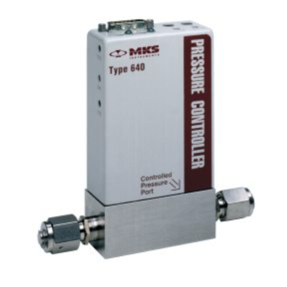
640B Series controller. The gas from the pressure system enters the controller on the transducer side, labeled “Controlled Pressure Port.” Figure 2 shows the gas flow for upstream control. -
Page 29: Dimensions
Label 0.50 (12.6) 3.00 4-VCR (76.2) Dimension A male compatible Back View Front View Figure 3: Front and Back Views of the Side Port 640B Series Controller Fitting Dimension Fitting Type Dimension A 0.94 (23.8) Cajon 4-VCR Male 8-VCR Male 1.17 (29.7) -
Page 30: Figure 4: Side View Of The 640B Series Controller
The trip point setting is adjustable from 0 to 5 Volts. 0.19 (4.83) Test Jacks for Trip Points 5.29 (134.4) 0.75 (19.0) 1.50 (38.0) Figure 4: Side View of the 640B Series Controller (Side opposite pressure-controlled port) -
Page 31: Down Port Version
Chapter Two: Installation Dimensions Down Port Version Interface Connector Figure 5: Top View of the Down Port Type 640B Controller 5.522 (140.26) 0.020 0.985 +0.020 (0.51) (25.02 +0.51) Inlet Outlet 1.476 +0.025 (37.49 +0.63) Figure 6: Front and Side View of the Down Port Type 640... -
Page 32: Figure 7: Bottom View Of The Down Port 640
Dimensions Chapter Two: Installation 0.591+0.005 3.622+0.015 (15 +0.12) (92+0.38) 1.181+0.005 (30 +0.12) 4.14+0.02 (105.0+0.5) Figure 7: Bottom View of the Down Port 640 Figure 8: Bottom View of the Down Port Seals... -
Page 33: Side Port Controller Mounting Instructions
¼” Swagelok compatible Mounting Hardware The Side Port 640B Series controller has four threaded mounting holes on the bottom or base of the unit. Use #8-32 hardware to mount the unit. Figure 9 shows the location and dimension of the mounting holes. -
Page 34: Down Port Controller Mounting Instructions
Table 5: SEMI Specifications for Down Port Fitting Options Caution 1. Handle the 640B Down Port Controller with extreme care. Be especially careful when placing the 640B Down Port Controller upright on a surface. Any scratches, dings, or dents on the bottom surface of the controller will cause improper sealing and may create a leak. -
Page 35: How To Connect The C-Seal Fittings
Chapter Two: Installation Down Port Controller Mounting Instructions How To Connect the C-Seal Fittings Note This section covers the mounting instructions for both the SEMI 2787.1 compliant and 0.445” diameter C-seals. 1. Select the retainer and screws appropriate for the type of C-seal. There are two types of seal assemblies available: ... -
Page 36: Figure 10: Exploded View Of The C-Seal Components
Down Port Controller Mounting Instructions Chapter Two: Installation 4. Clean the sealing surfaces of the MFC and substrate using a clean room swab dampened with a solvent such as isopropyl alcohol. Wipe the surfaces in a circular pattern with light pressure. Blow-clean the surfaces with filtered nitrogen. Note Clean all re-used sealing surfaces prior to resealing. - Page 37 Chapter Two: Installation Down Port Controller Mounting Instructions 9. Place the controller and seal assembly onto the substrate; make sure to align the seals and screws properly. 10. Finger-tighten the screws evenly. Ensure that the controller is level or parallel to the substrate.
-
Page 38: How To Connect The W-Seal (Semi 2878.3) Fittings
Down Port Controller Mounting Instructions Chapter Two: Installation How To Connect the W-Seal (SEMI 2878.3) Fittings Note The gaskets used in the W-seal are also referred to as IGS (Integrated Gas Systems) gaskets. Replacement gaskets (part number UGF-6.35G) are available from Fujikin of America, Inc. 1. - Page 39 Chapter Two: Installation Down Port Controller Mounting Instructions 5. Align the controller with the substrate and set the controller in place. 6. Finger-tighten the four (4) M5 x 30 mm long socket head cap screws evenly. Ensure that the controller is level or parallel to the substrate. 7.
-
Page 40: Initial Configuration
Initial Configuration Chapter Two: Installation Initial Configuration The 640B Series Pressure Controller is shipped from the factory with the configuration listed in Table 8. Initial Configuration Feature Setting Options Pressure Control Downstream Upstream Set Point Input* 0 to 5 V... - Page 41 Chapter Two: Installation Initial Configuration This page intentionally left blank.
-
Page 43: Chapter Three: Overview
Figure 12: Top View of the 640B Series Controller Pressure Control Range The 640B Series controller can control pressure over a range of 2% to 100% of full-scale. This means that a 640B controller with a 1000 Torr transducer can control pressure from 20 to 1000... -
Page 44: A Typical Control System
General Information Chapter Three: Overview A Typical Control System The 640B Series Pressure Controllers are used in a wide variety of control systems, most of which share several characteristics. Typically, a control system consists of four basic parts: Pressure transducer ... -
Page 45: How The 640B Series Pressure Controller Works
Figure 13: Sample Pressure Control System When the actual pressure reading is less than the set point value, the 640B Series controller opens the valve to increase the amount of gas entering the system. As the valve opens, gas enters the pressure system, so the pressure rises to meet the set point value. -
Page 46: Tuning The 640B Series Pressure Controller
Adjusting the Proportional Control The Proportional (P) term adjustment is located on the top of the 640B Series unit, as shown in Figure 11, page 31. The control is a 10-position dial, though it uses only 8 values. The last positions, 8 and 9, repeat the values of positions 0 and 1. -
Page 47: Integral Term
Figure 15: Effects of the Integral Control Adjusting the Integral Control The Integral (I) term adjustment is located on the top of the 640B Series unit, as shown in Figure 11, page 31. The control is a 10-position dial where the 0 setting has the longest integration time;... -
Page 48: Tuning The 640B Controller
Tune the system to provide the best response in the direction of pressure change that you anticipate. The following graphs show the response of the 640B controller to changes in the set point. The set point changed from 4 Torr (2 Volts) to 6 Torr (3 Volts), and back again. The pressure response was tracked using a digital storage oscilloscope. -
Page 49: Figure 17: Controller Response With Increased P Term
Chapter Three: Overview Tuning the 640B Series Pressure Controller Controller Response with Increased P Term Increasing the P term to 1 while holding the I term at 0 yields: Settling Time Settling Time P = 1 Set Point I = 0... -
Page 50: Priority Of Commands
(pin 2) or any signal on the Optional Input pin (pin 10) to the set point. The 640B Series controller positions its valve to achieve or maintain the set point pressure (or other variable if the Optional Input is used) in the system. -
Page 51: Trip Points
Trip Points Trip Points The 640B Series controller provides two trip points (Trip Point A and Trip Point B). Each trip point operates independently and controls an open collector output that can be connected to an external relay. Each trip point has an adjustment pot, a status LED, and a test jack. Refer to Figure 11, page 31, for the location of the trip point adjustment pots and LEDs. -
Page 52: Applications With A Large Differential Pressure
Labels The 640B Series controller carries a serial number label which identifies the serial number, model number, full-scale pressure range. It also displays the CE Mark which indicates compliance with European directives. The serial number label is located on the back of the unit. -
Page 53: Chapter Four: Operation
Figure 3, page 17, shows the labels on the unit. How To Zero a Type 640B (Absolute) Unit To zero a 640B controller (with an absolute transducer inside) you must pump the unit, with the power on, down to a pressure less than the transducer’s resolution (0.01% of Full-scale). -
Page 54: How To Zero A Type 641 (Gage) Unit
To properly zero a 640B controller (that contains an absolute transducer): 1. Install the 640B controller in a system and connect a power supply/readout. The pressure signal is available on pin 2 of the I/O connector. Use either pin 11 or 12 as the ground. -
Page 55: How To Adjust The Span
Center for calibration. How To Tune the 640B Series Controller You may need to tune the 640B Series controller to optimize how it controls your system. Tuning consists of varying the P (Proportional) and I (Integral) parameters to achieve the fastest, smoothest response to changes in the set point value. -
Page 56: How To Adjust The Trip Point Values
How to Adjust the Trip Point Values Chapter Four: Operation How to Adjust the Trip Point Values Equipment required: a digital voltmeter (DVM) Each trip point has a test jack that allows you to measure the trip point setting. The test jacks are located on the side of the unit. -
Page 57: How To Select The Trip Point Action
How to Select the Trip Point Action The 640B Series controller is initially configured with TP A set to trip high (it is on when the pressure is above the trip point pressure) and TP B set to trip low (it is on when the pressure is below the trip point pressure). - Page 58 How to Select the Trip Point Action Chapter Four: Operation The board silk-screening defines the jumper positions. TH indicates that the trip point will be on when the pressure is above the trip point, and TL indicates that the trip point will be on when the pressure is below the trip point.
-
Page 59: How To Use Trip Points As Error Indicators
47.5 to 52.5 Torr. The 640B Series controller is initially configured with TP A on above the trip point and TP B on below the trip point. If you have not changed the action of either trip point, you may follow the steps below. -
Page 60: How To Change The Pressure Output Signal Range
5. Position the controller with the front side facing you, and pull up on the enclosure to remove it. The MKS logo is displayed on the front of the unit. The board assembly will be visible, with the Transducer board facing you. The Control board is connected to the back of the Transducer board. -
Page 61: How To Select Upstream Control
How to Select Upstream Control How to Select Upstream Control The 640B Series controller is configured for downstream control when it leaves the factory. To use it in a upstream control application, you must remove the enclosure cover and reposition switch SW303 on the Control board. - Page 62 How to Select Upstream Control Chapter Four: Operation 6. Slide switch SW303 to the right for upstream control. Figure Error! Bookmark not defined., page 49, shows the switch configured to operate with a normally closed valve. 7. Slide the enclosure over the unit and press it in place. 8.
-
Page 63: Appendix A: Product Specifications
0.04% Reading/C Span Pressure output signal includes controller error, linearity, hysteresis, and repeatability. An overall metal braided shielded cable, properly grounded at both ends, is required during use. Consistent with the overpressure limit of the transducer within the 640B Series controller. -
Page 64: Environmental Specifications
Environmental Specifications Appendix A: Product Specifications Environmental Specifications Operating Temperature Range 0 to 50 C (32 to 122 F) Storage Temperature Range -20 to 80 C (-4 to 176 F) Storage Humidity Range 0 to 95% Relative Humidity, non-condensing Trip Point Specifications Trip Points Two open collector transistors, adjustable from 0 to 100% full-scale... -
Page 65: Physical Specifications
Appendix A: Product Specifications Physical Specifications Physical Specifications 1500 psig Burst Pressure Dimensions 1.5 in x 3.0 in (less fittings) x 5.55 in max. 3.81 cm x 7.62 cm (less fittings) x 14.1 cm max. Fittings Cajon 4-VCR male compatible, 8-VCR male compatible, ¼... - Page 66 Physical Specifications Appendix A: Product Specifications This page intentionally left blank.
-
Page 67: Appendix B: Valve Orifice Selection
The 640B controller is available in seven (7) valve orifice sizes. You should confirm that the valve orifice in your 640B controller is the correct size for your application before you install it into your system. The orifice is not adjustable and is only replaceable at the factory. -
Page 68: How To Verify The Orifice Selection
How to Verify the Orifice Selection Appendix B: Valve Orifice Selection How to Verify the Orifice Selection The correct orifice depends on three pieces of information: the upstream pressure, the downstream pressure, and the flow rate. These instructions assume that you are using nitrogen gas. - Page 69 2 covers the range at 1 atm P), whereas orifice number 3 covers from 1 to 1000 sccm (N from 5 to 5000 sccm. Figure 13: Flow Range Selection 4. Check the orifice size of your 640B controller (included in the model number).
-
Page 70: Using Different Gases
How to Verify the Orifice Selection Appendix B: Valve Orifice Selection Using Different Gases The valve orifice selection data is based on nitrogen gas. If you will be using a gas other than nitrogen, you need to compensate for the density difference between nitrogen and your process gas before you can select the appropriate valve orifice. -
Page 71: Appendix C: Gas Density Table
Appendix C: Gas Density Table Appendix C: Gas Density Table SYMBO DENSITY g/l @ 0 o C - - - 1.293 Ammonia 0.760 Argon 1.782 Arsine 3.478 Boron Trichloride 5.227 Bromine 7.130 Carbon Dioxide 1.964 Carbon Monoxide 1.250 Carbon Tetrachloride 6.86 Carbon Tetraflouride 3.926... - Page 72 Appendix C: Gas Density Table SYMBOL DENSITY g/l @ 0 o C Dichlorosilane 4.506 1,2- 7.626 Dichlorotetrafluoroethane (Freon - 114) 2.857 1,1-Difluoroethylene (Freon - 1132A) 3.219 2,2-Dimethylpropane 1.342 Ethane Fluorine 1.695 Fluoroform 3.127 (Freon - 23) Freon - 11 6.129 Freon - 12 5.395 CClF...
- Page 73 Appendix C: Gas Density Table SYMBOL DENSITY g/l @ 0 o C Hydrogen Chloride 1.627 Hydrogen Fluoride 0.893 Isobutylene 2.503 Krypton 3.739 Methane 0.715 Methyl Fluoride 1.518 Molybdenum Hexafluoride 9.366 Neon 0.900 Nitric Oxide 1.339 Nitrogen 1.250 Nitrogen Dioxide 2.052 Nitrogen Trifluoride 3.168 Nitrous Oxide...
- Page 74 Appendix C: Gas Density Table SYMBOL DENSITY g/l @ 0 o C Sulfur Hexafluoride 6.516 Trichlorofluoromethane 6.129 (Freon - 11) SiHCl Trichlorosilane 6.043 FCClF 1,1,2-Trichloro - 1,2,2-Trifluoroethane 8.360 2 or (Freon - 113) Tungsten Hexafluoride 13.28 Xenon 5.858 NOTE: Standard Pressure is defined as 760 mmHg (14.7 psia) Standard Temperature is defined as 0...
-
Page 75: Appendix D: Model Code Explanation
Model Code Description Appendix D: Model Code Explanation Model Code Description The model code number of your 640B Series Pressure Controller describes features of the unit, such as the pressure range, fittings, seal material, and orifice size (flow range). 64XB... -
Page 76: Figure 22: Model Code Explanation
1000 Torr 60 psi 100 psi Table 12: Pressure Range Selection Fitting Number (Y) The 640B Series controller has a range of fitting options, selected by a single letter code. Fitting Type Selection Fitting Choice Order Code Cajon 4-VCR, male Cajon 8-VCR, male ¼”... -
Page 77: Table 14: Valve Type
Appendix D: Model Code Explanation Model Code Description Valve Type (Z) The 640B Series controller has a normally closed valve, designated by a single number. Valve Type Valve Order Code Normally Closed Table 14: Valve Type Body Seal Material (Q) The control valve can use either one of a variety of elastomer seal materials, or an all-metal seal. -
Page 78: Table 16: Valve Orifice Size Selection
Model Code Description Appendix D: Model Code Explanation Valve Orifice Size (R) The 640B Series controller is available with one of seven (7) valve orifice sizes, defined by a single entry in the model code. Valve Orifice Size Selection Valve Orifice... -
Page 79: Table 18: Valve Plug Material
Appendix D: Model Code Explanation Model Code Description Valve Plug Material (T) A single letter defines the valve plug material. Valve Plug Material Material Order Code Viton Kalrez Metal Kel-F Table 18: Valve Plug Material... - Page 80 Model Code Description Appendix D: Model Code Explanation This page intentionally left blank.
-
Page 81: Index
Index Index Absolute pressure controller, 5 I/O connector, 13, 19-27 Inlet pressure, 15 Input power, 10 Baratron, 5, 32, 53 Installation, 10 Integral control, 28, 35, 43 Interface cables, 11 Cables, 9, 11, 12 CE compliance, 51 Commands, priority, 38 Label, 40 Connector, 9, 12, 13 Control board, 49... - Page 82 Index Proportional control, 29, 34, 43 Valve type, 65 Returning the product, 7, 9 Zero, 41–42 Seal material, 65 Set point, 13 Set point input, 14, 29, 34 Set point recognition, 38 Span adjustment, 43 Specifications environmental, 52 performance, 51 physical, 53 trip points, 52 Temperature, 10...
- Page 83 Index This page intentionally left blank.
- Page 84 Health and Safety Form...
Need help?
Do you have a question about the 640B and is the answer not in the manual?
Questions and answers