
Related Manuals for MKS 649B


Summary of Contents for MKS 649B
- Page 1 1023590-001 Rev B, 07/08 MKS Type 649B (ROHS Compliant) Pressure Controller with an Integral Mass Flow Meter Instruction Manual...
- Page 2 All rights reserved. No part of this work may be reproduced or transmitted in any form or by any means, electronic or mechanical, including photocopying and recording, or by any information storage or retrieval system, except as may be expressly permitted in writing by MKS Instruments, Inc.
-
Page 3: Table Of Contents
Table of Contents Table of Contents Safety Information ........................1 Symbols Used in This Instruction Manual..............1 Symbols Found on the Unit ....................2 Sicherheitshinweise........................5 In dieser Betriebsanleitung vorkommende Symbole ............5 Erklärung der am Gerät angebrachten Symbole .............5 Sicherheitsvorschriften und Vorsichtsmaßnahmen............6 Niemals Teile austauschen oder Änderungen am Gerät vornehmen! ..........6 Wartung nur durch qualifizierte Fachleute! .................6 Vorsicht vor stromführenden Leitungen!..................6 Vorsicht beim Arbeiten mit gefährlichen Stoffen!...............6... - Page 4 Table of Contents DÉPANNAGE UNIQUEMENT PAR DU PERSONNEL QUALIFIÉ........10 ÉLOIGNEMENT DES CIRCUITS SOUS-TENSION..............10 PRÉCAUTION EN CAS D'UTILISATION AVEC DES PRODUITS DANGEREUX .....10 PURGE DE L'APPAREIL ......................10 UTILISATION DES PROCÉDURES APPROPRIÉES POUR LA PURGE ......10 PAS D'EXPLOITATION DANS UN ENVIRONNEMENT EXPLOSIF ........10 UTILISATION D'ÉQUIPEMENTS ET PROCÉDURES DE SERRAGE APPROPRIÉS ..10 VÉRIFICATION DE L'ÉTANCHÉITÉ...
- Page 5 Table of Contents COMPRUEBE QUE LOS ACCESORIOS SEAN A PRUEBA DE FUGAS ......14 HAGA FUNCIONAR EL INSTRUMENTO CON PRESIONES DE ENTRADA SEGURAS ...........................14 INSTALE UNA CÁPSULA DE SEGURIDAD ADECUADA ..........14 MANTENGA LA UNIDAD LIBRE DE CONTAMINANTES..........14 CALIENTE ADECUADAMENTE LAS UNIDADES CONTROLADAS POR MEDIO DE TEMPERATURA........................15 安全に関する情報...
- Page 6 Table of Contents 장치에 표시된 기호들....................1 안전 절차 및 예방조치....................2 부품을 교체하거나 기계를 개조하지 마십시오..............2 자격이 있는 사람에게만 서비스를 받으십시오..............2 전류가 통하는 회로에서 분리해 보관하십시오..............2 위험한 물질과 함께 작동할 때는 주의를 기울이십시오............2 기계를 청소하십시오.........................2 청소 시에는 적절한 절차를 사용하십시오................2 폭발성 환경에서 작동하지 마십시오..................2 적절한...
- Page 7 Table of Contents Generic Shielded Cable Description..............11 Product Location and Requirements................12 Dimensions ........................13 Front and Back Views..................13 Side View......................14 Bottom View......................15 Setup ..........................16 Fittings .......................16 Mounting Hardware...................16 Gas Pressure.......................16 Installing the Unit ....................17 Electrical Information .....................18 I/O Connector ....................18 Initial Configuration .......................20 Chapter Three: Overview......................21 General Information......................21 Pressure Control Range ..................21...
- Page 8 Table of Contents How To Check the Pressure Transducer Zero ..............33 How To Adjust the Pressure Transducer Span ...............34 How To Zero the Integral Mass Flow Meter ..............35 How To Tune the 649 Controller..................36 How To Adjust the Trip Point Values ................37 How To Select the Trip Point Action ................38 How To Use Trip Points as Error Indicators..............40 How To Change the Pressure Output Signal Range ............41...
- Page 9 Table of Contents...
- Page 11 List of Figures List of Figures Figure 1: Front View of the Type 649 Controller...............14 Figure 2: Back View of the Type 649 Controller ...............14 Figure 3: Side View (Inlet) of the Type 649 Controller .............15 Figure 4: Bottom View of the Type 649 Controller..............15 Figure 5: Downstream Pressure Control..................17 Figure 6: Top View of the Type 649 Controller .................21 Figure 7: Location of the Mass Flow Meter Adjustments ............22...
- Page 12 List of Figures...
- Page 13 List of Tables List of Tables Table 1: Definition of Symbols Found on the Unit ................ 2 Tabelle 2: Bedeutung der am Gerät angebrachten Symbole............5 Tableau 3: Définition des symboles sur l'unité ................9 Tabla 4: Definición de los símbolos hallados en la unidad............13 表...
- Page 14 List of Tables...
-
Page 15: Safety Information
Safety Information Safety Information Symbols Used in This Instruction Manual Definitions of WARNING, CAUTION, and NOTE messages used throughout the manual. Warning The WARNING sign denotes a hazard. It calls attention to a procedure, practice, condition, or the like, which, if not correctly performed or adhered to, could result in injury to personnel. -
Page 16: Symbols Found On The Unit
Safety Information Symbols Found on the Unit The following table describes symbols that may be found on the unit. Definition of Symbols Found on the Unit Protective earth (ground) Earth (ground) On (Supply) Off (Supply) IEC 417, No.5019 IEC 417, No.5017 IEC 417, No.5008 IEC 417, No.5007 Frame or chassis... - Page 17 DO NOT SUBSTITUTE PARTS OR MODIFY INSTRUMENT Do not install substitute parts or perform any unauthorized modification to the instrument. Return the instrument to an MKS Calibration and Service Center for service and repair to ensure that all safety features are maintained.
- Page 18 Safety Information USE PROPER FITTINGS AND TIGHTENING PROCEDURES All instrument fittings must be consistent with instrument specifications, and compatible with the intended use of the instrument. Assemble and tighten fittings according to manufacturer's directions. CHECK FOR LEAK-TIGHT FITTINGS Before proceeding to instrument setup, carefully check all plumbing connections to the instrument to ensure leak-tight installation.
-
Page 19: Sicherheitshinweise
Sicherheitshinweise Sicherheitshinweise In dieser Betriebsanleitung vorkommende Symbole Bedeutung der mit WARNUNG!, VORSICHT! und HINWEIS gekennzeichneten Absätze in dieser Betriebsanleitung. Warnung! Das Symbol WARNUNG! weist auf eine Gefahr für das Bedienpersonal hin. Es macht auf einen Arbeitsablauf, eine Arbeitsweise, einen Zustand oder eine sonstige Gegebenheit aufmerksam, deren unsachgemäße Ausführung bzw. -
Page 20: Sicherheitsvorschriften Und Vorsichtsmaßnahmen
Ersetzen Sie keine Teile mit baugleichen oder ähnlichen Teilen, und nehmen Sie keine eigenmächtigen Änderungen am Gerät vor. Schicken Sie das Gerät zwecks Wartung und Reparatur an den MKS-Kalibrierungs- und -Kundendienst ein. Nur so wird sichergestellt, dass alle Schutzvorrichtungen voll funktionsfähig bleiben. -
Page 21: Bei Geräten Mit Temperaturkontrolle Korrekte Anwärmzeit Einhalten
Sicherheitshinweise Stellen Sie sicher, dass Verunreinigungen jeglicher Art weder vor dem Einsatz noch während des Betriebs in das Instrumenteninnere gelangen können. Staub- und Schmutzpartikel, Glassplitter oder Metallspäne können das Gerät dauerhaft beschädigen oder Prozess- und Messwerte verfälschen. Bei Geräten mit Temperaturkontrolle korrekte Anwärmzeit einhalten! Temperaturkontrollierte Geräte arbeiten nur dann gemäß... -
Page 23: Informations De Sécurité
Informations de Sécurité Informations de Sécurité Symboles utilisés dans ce manuel d'utilisation Définitions des indications AVERTISSEMENT, ATTENTION, et REMARQUE utilisées dans ce manuel. Avertissement L'indication AVERTISSEMENT signale un danger pour le personnel. Elle attire l'attention sur une procédure, une pratique, une condition, ou toute autre situation présentant un risque d'accident pour le personnel, en cas d'exécution incorrecte ou de non-respect des consignes. -
Page 24: Mesures De Sécurité Et Précautions
Ne pas installer de pièces de remplacement ni effectuer des modifications non autorisées sur l'appareil. Renvoyer l'appareil à un centre de service et de calibrage MKS pour tout dépannage ou réparation afin de garantir le l'intégrité des dispositifs de sécurité. -
Page 25: Respect Du Temps D'échauffement Approprié Pour Les Unités Á Régulation De Température
Informations de Sécurité RESPECT DU TEMPS D'ÉCHAUFFEMENT APPROPRIÉ POUR LES UNITÉS Á RÉGULATION DE TEMPÉRATURE Les unités à régulation de température sont conformes à leurs spécifications uniquement quand on leur laisse un temps suffisant pour atteindre d'une manière stable la température d'exploitation. Ne pas remettre à zéro ou calibrer l'unité tant que l'échauffement n'est pas terminé. -
Page 27: Tabla 4: Definición De Los Símbolos Hallados En La Unidad
Medidas de Seguridad Medidas de Seguridad Símbolos usados en este manual de instrucciones Definiciones de los mensajes de advertencia, precaución y de las notas usados en el manual. Advertencia El símbolo de advertencia indica la posibilidad de que se produzcan daños personales. -
Page 28: Compruebe Que Los Accesorios Sean A Prueba De Fugas
No instale piezas que no sean originales ni modifique el instrumento sin autorización. Para asegurar el correcto funcionamiento de todos los dispositivos de seguridad, envíe el instrumento al Centro de servicio y calibración de MKS toda vez que sea necesario repararlo o efectuar tareas de mantenimiento. -
Page 29: Caliente Adecuadamente Las Unidades Controladas Por Medio De Temperatura
Medidas de Seguridad No permita el ingreso de contaminantes en la unidad antes o durante su uso. Los productos contaminantes tales como polvo, suciedad, pelusa, lascas de vidrio o virutas de metal pueden dañar irreparablemente la unidad. CALIENTE ADECUADAMENTE LAS UNIDADES CONTROLADAS POR MEDIO DE TEMPERATURA Las unidades controladas por medio de temperatura funcionarán de acuerdo con las especificaciones sólo cuando se las caliente durante el tiempo suficiente para permitir que lleguen y se estabilicen a la temperatura de operación indicada. -
Page 31: 安全に関する情報
安全に関する情報 安全に関する情報 本取扱説明書のマーク 本マニュアルでは警告、注意、ポイントのマークを用いて重要な事項を記載しています。 警告 この表示を無視して誤った取り扱い (手順や使用方法、条件など) をすると、人が重傷 を負う可能性が想定される内容を示しています。必ずお読みください。 注意 この表示を無視して誤った取り扱い (手順や使用方法など) をすると、 製品が損傷する 可能性が想定される内容を示しています。必ずお読みください。 ポイント この表示は手順や使用方法、条件などに関する重要な情報が記載されていることを示 しています。必ずお読みください。 本機器のマーク 以下の表では、本機器に使用されているマークについて説明いたします。 表 5: 本機器に使用されているマークについて オン (電源) オフ (電源) 接地 (アース) 保護接地 (アース) IEC 417, No. 5007 IEC 417, No. 5008 IEC 417, No. 5017 IEC 417, No. -
Page 32: 勝手に部品を変えたり、本体を改造しないこと
安全に関する情報 損なわれる可能性があります。MKS Instruments, Inc. は、顧客側の安全対策の不履行に対して は一切責任を負いかねます。 勝手に部品を変えたり、本体を改造しないこと 本機器に代用部品を使用したり、不正な改造を加えないでください。すべての安全システムを正しく機能させるた めの修理やメンテナンスが必要な場合は、本機器を MKS Calibration and Service Center まで戻してください。 修理は必ず専門の修理サービスを利用すること オペレータは絶対に本機器を分解しないでください。部品の交換や内部の調整は必ず専門の修理サービスを利 用してください。 電流が通じている回路から切断すること 電源ケーブルを接続したままで部品を交換しないでください。特定の状況では、電源ケーブルを取り外した状態 でも危険な電圧が残っている場合があります。感電などの事故を防ぐため、回路に触れる前に必ず電源から切 断し、放電してください。 危険な材料を使用する場合は慎重に機器を使用すること 危険な材料を使用する場合は、使用者は各自の責任の元で適切な安全対策を講じてください。必要に応じて 本機器を浄化してください。また、使用する材料に対するシーリング材の耐久性を確認してください。 機器を浄化すること 本機器を取り付けた後やシステムから取り外す前に、きれいな乾燥ガスで本機器を浄化し、使用した材料を完 全に取り除いてください。 浄化する場合は適切な手順で行うこと 本機器の浄化は換気フードの下で行う必要があります。また、浄化作業を行う人は必ず手袋を着用してください。 爆発の危険性のある環境で機器を使用しないこと 爆発が起きるのを防ぐため、本機器を爆発の危険性のある環境で使用しないでください。ただし、そのような環境 での使用が特別に保証されている場合は除きます。 適切な金具類を使用し、手順に従って金具の締めを行うこと 金具類は本機器の仕様と一致し、機器本来の用途に適合したものである必要があります。金具類の取り付け や締めは、製造業者の指示に従ってください。 液体の漏れがないよう接続箇所を確認すること 本機器を設定する前に、すべての配管の接続を慎重に確認し、液体が漏れないようにしてください。 安全なインレット圧力で使用すること 定格の最大圧力を超える圧力の下で本機器を絶対に使用しないでください (最大許容圧力については仕様書... -
Page 33: 장치 안전 정보
장치 안전 정보 장치 안전 정보 본 지침 매뉴얼에 사용되는 기호들 매뉴얼 전체에 사용되는 경고, 주의 및 참고 메시지의 정의. 경고 경고 표시는 위험을 나타냅니다. 이 표시는 올바르게 수행되거나 지켜지지 않을 경우, 사람에게 상해를 입힐 수 있는 절차, 수행지침, 상태 또는 이와 유사한 상황들에... -
Page 34: 안전 절차 및 예방조치
부품을 교체하거나 기계를 개조하지 마십시오 교체 부품을 설치하거나 기계에 허가되지 않은 어떠한 수정도 가하지 마십시오. 서비스와 수리가 필요한 경우에는 모든 안전 특성이 유지되도록 기계를 MKS 보정 서비스 센터 (MKS Calibration and Service Center) 로 보내주십시오. 자격이 있는 사람에게만 서비스를 받으십시오... -
Page 35: 장치를 오염이 없는 곳에 보관하십시오
장치 안전 정보 가압 가스 공급원에서 작동시, 시스템 폭발이 시스템 압력 상승을 일으키는 것을 방지하기 위해 적합한 안전 파열판이 진공 시스템에 설치되어야 합니다. 장치를 오염이 없는 곳에 보관하십시오 장치를 사용하기 전이나 사용 중에는 어떠한 종류의 오염 물질도 허용해서는 안됩니다. 먼지, 때, 보풀, 유리... -
Page 37: Chapter One: General Information
One Type “D” connector, located on the top of the unit, accepts the input power and has both the pressure (input and output) and flow (output) signals. You can connect the 649 controller to an MKS Type 247 or 246 Mass Flow Controller Power Supply/Readout or a Type 647 Mass Flow and Pressure Programmer/Display unit. -
Page 38: Cleanliness Features
How This Manual is Organized Chapter One: General Information gases with different densities, which dramatically improves measurement accuracy when gases other than the calibration gas are used. Cleanliness Features The design of the pressure controller ensures extremely low external leakage and minimizes a key source of particle generation, outgassing, and permeation. -
Page 39: Customer Support
MKS Calibration and Service Center before shipping. The RMA Number expedites handling and ensures proper servicing of your instrument. Please refer to the inside of the back cover of this manual for a list of MKS Calibration and Service Centers. - Page 40 Customer Support Chapter One: General Information This page intentionally left blank.
-
Page 41: Chapter Two: Installation
Chapter Two: Installation How To Unpack the Type 649 Unit MKS has carefully packed the Type 649 unit so that it will reach you in perfect operating order. Upon receiving the unit, however, you should check for defects, cracks, broken connectors, etc., to be certain that damage has not occurred during shipment. -
Page 42: Unpacking Checklist
How To Unpack the Type 649 Unit Chapter Two: Installation Unpacking Checklist Standard Equipment: • Type 649 Unit • Type 649 Instruction Manual (this book) Optional Equipment: • Electrical Connector Accessories Kit - 649A-K1 • Interface cables (refer to Interface Cables, page 11) -
Page 43: Interface Cables
Use a CB649S-1-Mx or CB649-1-Mx cable (where x indicates code for the length) to connect the 649 controller to an MKS Type 247 or 246 Mass Flow Controller Power Supply/Readout or a Type 647 Mass Flow and Pressure Programmer/Display unit. The standard cable, CB649-1-M1 is 10 feet in length. -
Page 44: Product Location And Requirements
Product Location and Requirements Chapter Two: Installation 5. In selecting the appropriate type and wire size for cables, consider: A. The voltage ratings; B. The cumulative I R heating of all the conductors (keep them safely cool); C. The IR drop of the conductors, so that adequate power or signal voltage gets to the device;... -
Page 45: Dimensions
Warning Follow your corporate policy for handling toxic or hazardous gases. Your corporate policy on handling these gases supersedes the instructions in this manual. MKS assumes no liability for the safe handling of such materials. • Install the 649 controller in a “flowing” system where gas is continually added and evacuated Do not use the controller in a “dead-ended”... -
Page 46: Side View
Dimensions Chapter Two: Installation Type 649 5.50 5.29 (139.8) (134.4) 4-VCR: 6.66 (169.2) 8-VCR: 7.11 (180.6) Figure 1: Front View of the Type 649 Controller Figure 2: Back View of the Type 649 Controller Side View The flow meter adjustments are located on the inlet side of the 649 controller. -
Page 47: Bottom View
Chapter Two: Installation Dimensions M FM Adjust Zero Span 0.50 (12.7) 0.74 (18.8) 1.48 (37.6) Figure 3: Side View (Inlet) of the Type 649 Controller Bottom View Mounting Hole Outlet Fitting 0.38 (9.5) 0.38 (9.5) Inlet Fitting Mounting Hole: 8-32 UNC-2B x 0.340 DP. 3.18 (80.7) 0.79 (20) 2 places... -
Page 48: Setup
Setup Chapter Two: Installation Setup This section covers how to install the 649 controller into your system. Fittings The 649 pressure controller is available with the following fittings: • Cajon 4-VCR male compatible • Cajon 8-VCR male compatible Mounting Hardware The 649 controller has two mounting holes located on the bottom or base of the unit. -
Page 49: Installing The Unit
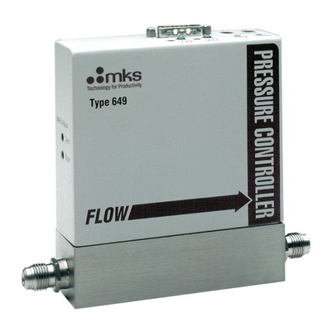
Chapter Two: Installation Setup Installing the Unit The 649 Pressure Controller should be mounted to provide downstream pressure control. Connect the controller so that the flow arrow points toward the system whose pressure you need to control. Note Connect the 649 controller to your system so that the gas flows in the direction of the flow arrow on the front of the unit. -
Page 50: Electrical Information
Electrical Information Chapter Two: Installation Electrical Information I/O Connector The 649 controller has one 15-pin, male Type “D” connector that provides the pressure output, set point input, and trip point output signals. Refer to Figure 6, page 21, for the location of the connector. - Page 51 Chapter Two: Installation Electrical Information Set Point Input (Pin 8) The set point input signal can be a 0 to 10 Volt (factory setting) or 0 to 5 Volt signal. The range of the set point input signal must match the range of the pressure output signal. The 649 controller is initially configured for a 0 to 10 Volt pressure output signal.
-
Page 52: Initial Configuration
Initial Configuration Chapter Two: Installation Initial Configuration The 649 pressure controller is shipped from the factory with the configuration listed in Table 8. Initial Configuration Feature Setting Options Pressure Control Downstream no option Set Point Input* 0 to 10 V 0 to 5 V Pressure Output 0 to 10 V... -
Page 53: Chapter Three: Overview
Chapter Three: Overview General Information Chapter Three: Overview General Information Figure 6 shows the top view of the 649 pressure controller. The user adjustable controls for pressure zero, pressure span, the P term, the I term, and the trip points are located on the top of the controller. -
Page 54: Flow Range
The 649 Pressure Controller provides the first three components. The pressure transducer is an MKS Baratron capacitance manometer. The 649 unit contains the electronics necessary for pressure control. The control valve included in the 649 controller is a proportional control valve. -
Page 55: How The 649 Pressure Controller Works
Chapter Three: Overview How The 649 Pressure Controller Works How The 649 Pressure Controller Works The 649 controller compares the pressure reading to the set point, and positions the valve to maintain, or achieve, the set point pressure. The controller functions as a PI (Proportional- Integral) controller. -
Page 56: Flow Measurement Overview
Flow Measurement Overview Chapter Three: Overview Flow Measurement Overview The 649 controller measures the mass flow rate of a gas. Flow Path Upon entering the 649 controller, the gas stream passes first through the metering section of the instrument for its mass flow to be measured. The gas moves on through the control valve, which regulates the pressure according to the given set point, and then exits the instrument at the established pressure. -
Page 57: Tuning The 649 Pressure Controller
Chapter Three: Overview Tuning the 649 Pressure Controller Tuning the 649 Pressure Controller Tuning optimizes the way the 649 unit controls your system. The Proportional (P) and Integral (I) terms adjust the response of the 649 controller. The controller responds to changes in either the pressure of the system or the value of the set point. -
Page 58: Integral Term
Tuning the 649 Pressure Controller Chapter Three: Overview Integral Term The action of the Integral (I) term creates a valve drive signal that is proportional to the magnitude and sign of the area under the error signal curve (error signal with respect to time). Therefore, as time passes, the integral term acts to position the valve to reduce the error signal to zero. -
Page 59: Tuning The 649 Controller
Chapter Three: Overview Tuning the 649 Pressure Controller Tuning the 649 Controller Tuning the 649 controller involves adjusting the Proportional and Integral terms to optimize the response of the controller in your system. Since every system is different, the optimum settings for the P term and I term will vary. -
Page 60: Figure 11: Controller Response With Increased P Term
Tuning the 649 Pressure Controller Chapter Three: Overview Controller Response with Increased P Term Increasing the P term to 1 while holding the I term at 0 yields: Settling Time Settling Time P = 1 Set Point I = 0 Signal Time Figure 11: Controller Response with Increased P Term... -
Page 61: Priority Of Commands
Chapter Three: Overview Priority of Commands Priority of Commands The 649 controller has an established hierarchy that it uses to determine which commands take precedence. The commands and operating modes are listed according to the order of priority (from highest to lowest): •... -
Page 62: Trip Points
Trip Points Chapter Three: Overview Trip Points The 649 controller provides two trip points (Trip Point A and Trip Point B). Each trip point operates independently and controls an open collector output that can be connected to an external relay. Each trip point has an adjustment pot, a status LED, and a test jack. Refer to Figure 6, page 21, for the location of the trip point adjustment pots and LEDs. -
Page 63: Applications With A Large Differential Pressure
Chapter Three: Overview Applications with a Large Differential Pressure Applications with a Large Differential Pressure Applications with a large differential pressure between the inlet and outlet, or a large inlet pressure, may require special precautions: • If the inlet pressure is more than two times the pressure transducer full scale pressure or [310 kPa], whichever is greater You must ensure that the valve will never be fully opened to the pressure transducer. - Page 64 Labels Chapter Three: Overview This page intentionally left blank.
-
Page 65: Chapter Four: Operation
Check the pressure transducer zero before operating the unit initially and then periodically as required. The zero can be set (or reset) by adjusting the zero potentiometer located on the top cover of the 649 controller or, on the front panel of an MKS Power Supply/Readout, if you are using one. -
Page 66: How To Adjust The Pressure Transducer Span
How To Adjust the Pressure Transducer Span Only adjust the pot in conjunction with a calibration transfer standard. Do not adjust the SPAN span setting if a calibration transfer standard is not available. Instead, contact an MKS Service Center for calibration. -
Page 67: How To Zero The Integral Mass Flow Meter
Chapter Four: Operation How To Zero the Integral Mass Flow Meter How To Zero the Integral Mass Flow Meter Ensure that no gas flow is entering the 649 controller. 1. Apply gas, at a regulated pressure, to the 649 controller. 2. -
Page 68: How To Tune The 649 Controller
How To Tune the 649 Controller Chapter Four: Operation How To Tune the 649 Controller You may need to tune the 649 controller to optimize how it controls your system. Tuning consists of varying the P (Proportional) and I (Integral) parameters to achieve the fastest, smoothest response to changes in the set point value. -
Page 69: How To Adjust The Trip Point Values
Chapter Four: Operation How To Adjust the Trip Point Values How To Adjust the Trip Point Values Equipment required: digital volt meter (DVM) 4.8 mm hex or open-ended wrench Caution Only qualified individuals should perform the adjustments. You must comply with all the necessary ESD and handling precautions while adjusting the instrument. -
Page 70: How To Select The Trip Point Action
How To Select the Trip Point Action Chapter Four: Operation 6. Use a small screwdriver to adjust the trip point adjustment pot labeled “TP A”. Refer to Figure 6, page 21, for the location of the trip point adjustment pots. Turning the pot clockwise raises the trip point setting. -
Page 71: Figure 14: Jumper Positions On The Transducer Board
Chapter Four: Operation How To Select the Trip Point Action Figure 14: Jumper Positions on the Transducer Board 5. Position the jumper on jumper block “JP4” to select the action for TP A. Jumper block “JP3” controls TP B. The board silk-screen defines the jumper positions. TH indicates that the trip point will be on when the pressure is above the trip point, and TL indicates that the trip point will be on when the pressure is below the trip point. -
Page 72: How To Use Trip Points As Error Indicators
How To Use Trip Points as Error Indicators Chapter Four: Operation How To Use Trip Points as Error Indicators You can use the trip points to indicate when the error signal deviates from a given range. The error is defined as the difference between the actual pressure reading and the set point. For example, assume you have a 100 Torr [13.33 kPa] unit and your set point is 50 Torr [6.666 kPa]. -
Page 73: How To Change The Pressure Output Signal Range
6. Position the controller with the front side facing you, and pull up on the enclosure to remove it. The MKS logo is displayed on the front of the unit. The board assembly will be visible, with the Transducer board facing you. The Control board is connected to the back of the Transducer board. - Page 74 How To Change the Pressure Output Signal Range Chapter Four: Operation 11. Slide the enclosure cover over the unit. 12. Attach the hex nuts to the I/O connector and Philip screws removed in step 3. 13. Reconnect the leads and wires.
-
Page 75: Chapter Five: Maintenance
It is also recommended that the instrument be recalibrated annually if no other time interval has been specifically established. Refer to the inside of the back cover of this instruction manual for a complete list of MKS Calibration and Service centers. - Page 76 Zero Adjustment Chapter Five: Maintenance This page intentionally left blank.
-
Page 77: Appendix A: Product Specifications
Appendix A: Product Specifications Performance Specifications Appendix A: Product Specifications Performance Specifications Accuracy ± 0.5% Reading Pressure Transducer ≤ ± 0.1% F.S. Pressure Controller Mass Flow Meter ±1.0% F.S. typical CE Compliance Electromagnetic Compatibility EMC Directive 89/336/EEC Control Adjustments Integral 10 positions (0 through 9) Proportional 8 positions (0 through 7;... -
Page 78: Physical Specifications
Physical Specifications Appendix A: Product Specifications Physical Specifications ≥ 1500 psia [1.03 x 10 Burst Pressure kPa] Dimensions 3.81 cm x 12.07 cm (less fittings) x 14.1 cm max. ® ® Fittings Cajon 4-VCR male compatible, 8-VCR male compatible Full Scale Ranges Pressure 10 Torr [1.33 x 10 20 Torr [2.66 x 10... -
Page 79: Environmental Specifications
Appendix A: Product Specifications Environmental Specifications Environmental Specifications 0 ° to 50 ° C Ambient Operating Temperature Range -20 ° to 80 ° C Storage Temperature Range Storage Humidity Range 0 to 95% Relative Humidity, non-condensing Trip Point Specifications Trip Points Two open collector transistors, adjustable from 1 to 100% full scale Rated Current... - Page 80 Trip Point Specifications Appendix A: Product Specifications This page intentionally left blank.
-
Page 81: Appendix B: Model Code Explanation
649B Type Number Gas Code Pressure Range Flow Rate Valve Orifice Size Valve Plug Seat Material Fittings Type Number (649B) This designates the model number of the instrument. 649 B designates the ROHS compliant version of the 649 product. - Page 82 Model Code Appendix B: Model Code Explanation Gas Code (GGG) The gas code is indicated by a three digit code. Gas Code Ordering Code Helium Argon Hydrogen Nitrogen Full Scale Pressure Range (XXX) The full scale pressure range is indicated by a two digit/one letter code. Full Scale Pressure Range Ordering Code 10 Torr [1.33 x 10...
- Page 83 Appendix B: Model Code Explanation Model Code Valve Orifice Size (Z) The valve orifice size is designated by a single number or letter code. Refer to Appendix A: Product Specifications , page 45, for more information. Valve Orifice Ordering Code <100 sccm 200 sccm 1000 sccm...
- Page 84 Model Code Appendix B: Model Code Explanation This page intentionally left blank.
-
Page 85: Appendix C: Valve Orifice Selection
Appendix C: Valve Orifice Selection General Information Appendix C: Valve Orifice Selection General Information The 649 controller is available in four valve orifice sizes. You should confirm that the valve orifice in your 649 controller is the correct size for your application before you install it into your system. -
Page 86: How To Verify The Orifice Selection
How To Verify the Orifice Selection Appendix C: Valve Orifice Selection How To Verify the Orifice Selection The correct orifice depends on three pieces of information: the upstream pressure, the downstream pressure, and the flow rate. These instructions assume that you are using nitrogen gas. -
Page 87: Figure 15: Flow Range Selection
How To Verify the Orifice Selection 3. Use the index number and your maximum flow rate, to determine the orifice size from Figure 15. Each line represents the maximum flow rate for the orifice. Choose the orifice number above your point on the graph to ensure that the orifice can deliver the required flow. Continuing with the example above, the index number is 175, and assuming a maximum required flow rate of 1000 sccm, the correct orifice would be number 2. - Page 88 How To Verify the Orifice Selection This page intentionally left blank.
-
Page 89: Index
Index Index Accuracy, 51 Label, 31 Ambient temperature, 12, 47 Manual conventions, 6 Commands, priority, 29 Manual organization, 6 Connector, I/O, 18–19 Measurement technique, 24 Control range, pressure, 21 Model code, 49 Control system, 22 Mounting, 16, 17 Customer support, 7 Optional input, 19 Differential pressure, 31, 54 Orientation, 12, 17, 33... - Page 90 Index Safety procedures and precautions, 2 Set point, 19 Set point input, 20 Set point recognition, 29 Span adjustment, 34 Specifications environmental, 47 physical, 46 trip points, 47 Transducer board, 38 Trip point action, 38 Trip point values, 37 Trip points, 19, 20, 30 Tuning, 25–28 Unpacking opening, 9...
Need help?
Do you have a question about the 649B and is the answer not in the manual?
Questions and answers