Table of Contents
Advertisement
Quick Links
Advertisement
Table of Contents

Subscribe to Our Youtube Channel
Related Manuals for Beckhoff CP37-1600 Series


Summary of Contents for Beckhoff CP37-1600 Series
- Page 1 Manual | EN CP37xx-1600 Multi-touch Panel PC 9/15/2021 | Version: 1.1...
-
Page 3: Table Of Contents
Grounding the Panel PC.................... 33 4.3.2 Connecting cables and power supply ................ 35 Switching the Panel PC on and off .................... 36 5 Beckhoff Device Manager ........................ 38 6 Decommissioning............................ 40 Disconnecting the power supply and cables ................... 40 Disassembly and disposal ....................... 41 7 Maintenance ............................. 43 Cleaning ............................ 43... - Page 4 Table of contents 10.1 Service and support......................... 51 10.2 Approvals............................ 52 Version: 1.1 CP37xx-1600...
-
Page 5: Notes On The Documentation
Copyright © Beckhoff Automation GmbH & Co. KG. Publication of this document on websites other than ours is prohibited. Offenders will be held liable for the payment of damages. All rights reserved in the event of the grant of a patent, utility model or design. -
Page 6: For Your Safety
Exclusion of liability Beckhoff shall not be liable in the event of non-compliance with this documentation and thus the use of the devices outside the documented operating conditions. -
Page 7: Fundamental Safety Instructions
For your safety Fundamental safety instructions The following safety instructions must be observed when handling the device. Application conditions • Do not use the device under extreme environmental conditions. Protect the device from moisture and heat. • Never use the device in potentially explosive atmospheres. •... -
Page 8: Product Overview
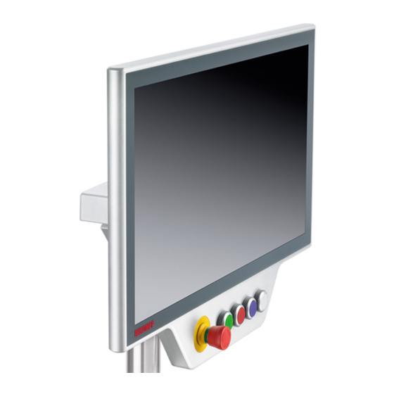
Product overview Product overview With the CP37xx-1600 series you can use multi-touch directly in the field. The devices in the robust aluminum housing are designed for mounting arm installation. The connection cables are routed through the mounting arm. Thanks to its processors, you can use the Panel PC for the following applications, among others: •... -
Page 9: Fig. 1 Cp37Xx-1600_With And Without Push Button Extension
Product overview Fig. 1: CP37xx-1600_with and without push button extension CP37xx-1600 Version: 1.1... -
Page 10: Structure
Product overview Structure Figure 3 shows the structure of the device as an example of all CP37xx-1600 variants. Fig. 2: CP37xx-1600_configuration Table 1: CP37xx-1600 configuration legend Component Description Mounting arm tube Mounting arm tube for installation from below or above USB interface under screw cap Connection of peripheral devices Name plate Information on the equipment of the Panel PC... -
Page 11: Interface Description
Product overview Interface description In the basic configuration, the Panel PC includes the following interfaces: • Power supply (X101) • Ethernet RJ45 (X102) • USB The voltage socket and the Ethernet interface are located at the rear in the connection compartment of the PC. -
Page 12: Power Supply
The main supply voltage is applied between pins 5 (0 V) and 6 (24 V). If the Panel PC is equipped with an integrated uninterruptible power supply (UPS), an external battery can additionally be connected to PIN 1 and PIN 2. The two Beckhoff options C9900-U330 and C9900-U332 are available for this purpose. -
Page 13: Fig. 5 Cp37Xx-1600_Ethernet Interface Pin Numbering
Product overview The RJ45 connection technology with twisted-pair cables is used. The maximum length of the cable connection is 100 m. The Ethernet port is suitable for cycle times <= 1 ms and for distributed clock applications with EtherCAT. ® An Intel i210 is used as controller. -
Page 14: Usb
Product overview 3.2.3 The Panel PC has a USB 3.0 interface. This is used to connect peripheral devices with USB connection. The interface is located behind a screw cap. It supplies 900 mA current and is electronically fused. Fig. 6: CP37xx-1600_USB interface pin numbering Table 5: USB interface pin assignment Assignment Shield... -
Page 15: Optional Interfaces
Product overview Optional interfaces You can expand the Panel PC beyond the basic configuration with additional interfaces in the connection compartment. The following ordering options are available: • Ethernet RJ45 (order identifier: C9900-B416) • Ethernet RJ45 (order identifier: C9900-E185) • RS232 (order identifier: C9900-E186) •... -
Page 16: Rs232
Product overview 3.3.2 RS232 The optional RS232 interface includes an M12 socket according to IP65. The interface provides an asynchronous, serial communication method defined in the RS232 standard. Fig. 8: CP37xx-1600_RS232 interface pin numbering Table 7: RS232 pin assignment Signal Type Description Carrier recognized Signal in Receive Data... -
Page 17: Rs485
Product overview Table 9: RS422 standard configuration Function Status Echo Auto send Always send Auto receive Always receive Termination 3.3.4 RS485 The optional RS485 serial interface includes an electrically isolated M12 IP65 socket for high-speed serial data transmission. The channel features overvoltage protection. If an overvoltage occurs, the channel is switched off. 11 12 Fig. 10: CP37xx-1600_RS485 interface pin numbering Table 10: RS485 pin assignment... -
Page 18: Usb
Product overview 3.3.5 The additional optional USB interfaces are used to connect peripheral devices with USB ports. The factory- installed interfaces are located in the connection compartment of the Panel PC. Depending on the ordering option selected, either USB specification 2.0 or 3.0 is supported. The following ordering options are available: Table 12: Ordering options for USB interfaces Options... -
Page 19: Name Plate
Product overview Name plate xxxxxxxx xxxxxxxxxxxxx xxxxxxxxxxxxx Fig. 12: CP37xx-1600_name plate Table 14: Legend for CP37xx-1600 name plate Description Model: The last four digits indicate the product variant. Serial number (BTN) Date of manufacture Mainboard Storage media Hard disk MAC addresses of the Ethernet interfaces Power supply: 24 V , NEC class 2 Symbols... -
Page 20: Connecting Cable
Product overview Connecting cable Optionally, ready-made connection cables for all connections are available in various lengths. You can order them using the following article descriptions: Table 15: Power supply cable Connection cable Power supply cable with IP65 plug C9900-K271 Power supply cable IP 65 for CP32xx, CP37xx or CP72xx, length 5 m, pre- assembled, M23 socket, screw-type, 8-wire, second end open C9900-K272 Power supply cable IP 65 for CP32xx, CP37xx or CP72xx, length 10 m, pre-... - Page 21 Product overview Connection cable Serial interface cable RS232 with IP 65 connector C9900-K297 Serial interface cable RS232 for CP32xx, CP37xx or CP72xx, length 10 m, pre- assembled, M12 plug connector IP 65, screw-type, 12-pin, second end D-Sub 9 connector CP37xx-1600 Version: 1.1...
-
Page 22: Commissioning
Beckhoff protective film. The film provides short-term protection for a few days. You can either order a Beckhoff protective film individually and fit it yourself retrospectively, or you can order the film for fitting directly ex works. -
Page 23: Transport And Storage
5. Check the contents for visible shipping damage. 6. In case of discrepancies between the package contents and the order, or in case of transport damage, please inform Beckhoff Service (see Chapter 10.1 Service and support [} 51]). CP37xx-1600 Version: 1.1... -
Page 24: Mounting
Installing the mounting arm adapter If you have chosen one of the two mounting arm adapters from Beckhoff referred to above, the installation procedure is the same in both cases. Before the installation you have to decide whether you want to orient the device upwards or downwards (see Fig. -
Page 25: Fig. 14 Cp37Xx-1600_Orientation Of The Mounting Arm Adapter
Commissioning Fig. 14: CP37xx-1600_orientation of the mounting arm adapter To fasten the mounting arm adapter to the Panel PC, follow the steps below, shown in Fig. 15: 1. Remove the cover of the mounting arm adapter (section A). For the exact procedure see chapter 3.2 Interface description [} 11]. -
Page 26: Fig. 16 Cp37Xx-1600_Mounting Arm Adapter Installed
Commissioning Fig. 16: CP37xx-1600_mounting arm adapter installed A strain relief plate is located inside the mounting arm adapter. You can relocate this according to your requirements. Version: 1.1 CP37xx-1600... -
Page 27: Dimensions
Commissioning 4.2.1 Dimensions All dimensions are in mm. Fig. 17 shows the dimensions of the 15-inch Panel PC. 63,5 325,2 360,8 37,5 Fig. 17: CP3715-1600_dimensions Fig. 18 shows the dimensions of the 15.6-inch Panel PC. 67,5 325,2 405,8 37,5 Fig. 18: CP3716-1600_dimensions Fig. -
Page 28: Fig. 19 Cp3716-1600_Push Button Extension Dimensions
Commissioning 67,5 325,2 37,5 405,8 33,5 Fig. 19: CP3716-1600_push button extension dimensions Fig. 20 shows the dimensions of the 18.5-inch Panel PC. 64,5 325,2 471,8 37,5 Fig. 20: CP3718-1600_dimensions Fig. 21 shows the dimensions of the 18.5-inch Panel PC with push button extension. 65,5 325,2 471,8... -
Page 29: Fig. 22 Cp3719-1600_Dimensions
Commissioning Fig. 22 shows the dimensions of the 19-inch Panel PC. 3x M5 - 6H 66,5 325,2 433,2 37,5 Fig. 22: CP3719-1600_dimensions Fig. 23 shows the dimensions of the 21.5-inch Panel PC. 65,5 325,2 537,2 37,5 Fig. 23: CP3721-1600_dimensions Fig. 24 shows the dimensions of the 21.5-inch Panel PC with push button extension. CP37xx-1600 Version: 1.1... -
Page 30: Fig. 24 Cp3721-1600_Push Button Extension Dimensions
Commissioning 65,5 325,2 537,2 37,5 33,5 Fig. 24: CP3721-1600_push button extension dimensions Fig. 25 shows the dimensions of the 24-inch Panel PC. 65,5 325,2 592,2 37,5 Fig. 25: CP3724-1600_dimensions Fig. 26 shows the dimensions of the 24-inch Panel PC with push button extension. 65,5 325,2 592,2... -
Page 31: Mounting Arm Tube Installation
Among other tools you need a hook wrench for the installation. You can order this from your Beckhoff Sales using the following order identifier: •... -
Page 32: Installing A Toolboard And Handle
Commissioning 4.2.3 Installing a toolboard and handle You have the option of retrofitting mechanical extensions such as a handle or a toolboard to your Panel PC. The following ordering options are available: Table 22: Ordering options for handle and toolboard Order identifier Execution C9900-M361 Handle, length = 386 mm, anodized aluminum, mounted on the underside of a... -
Page 33: Connecting The Panel Pc
Commissioning Connecting the Panel PC CAUTION Risk of electric shock Dangerous touch voltages can lead to electric shock. To avoid electric shock, adhere to the following points: • Never connect or disconnect the device cables during a thunderstorm. • Provide protective earthing for handling the device. To make the Panel PC ready for operation, you have to connect it. -
Page 34: Fig. 30 Cp37Xx-1600_Mounting Arm Adapter Grounding Bolt
Commissioning Fig. 30: CP37xx-1600_mounting arm adapter grounding bolt Protective earth Establish low-resistance protective earthing of the Panel PC via the voltage connection to avoid dangerous touch voltages. There is a pin in the voltage socket for the protective earth (PE). NOTE Hardware damage due to electromagnetic interference The use of the panel PC without a functional earth can lead to material damage due to electromagnetic in- terference. -
Page 35: Connecting Cables And Power Supply
If you ordered your device with an integrated UPS, then you can connect an external battery pack and install it on a DIN rail near to the PC. Use only Beckhoff battery packs for this: • C9900-U330: Universal battery pack for PCs and Panel PCs in any configuration •... -
Page 36: Switching The Panel Pc On And Off
• Avoid switching off the power supply before shutting down the operating system. • Use the Beckhoff concept (see below) to shut down the operating system in a battery-friendly manner. When the system is switched off or disconnected from its own power supply, the Panel PC is also switched off. - Page 37 Beckhoff Service (service@beckhoff.com), which will provide you with the software and drivers. The driver software comes with a detailed help function. Call up the help files either directly from the configuration register by clicking the Help button or start the file under Start > Programs > Beckhoff > UPS software components.
-
Page 38: Beckhoff Device Manager
• User name: Administrator • Password: 1 You also have the option of using the Beckhoff Device Manager to remotely configure the Industrial PC via a web browser. More detailed information is available in the Beckhoff Device Manager manual. First start Beckhoff Device Manager When your Industrial PC is booted for the first time, the Beckhoff Device Manager also starts automatically for the first time. -
Page 39: Fig. 32 Beckhoff Device Manager - Start Page
Secure passwords Strong passwords are an important prerequisite for a secure system. Beckhoff supplies the device images with standard user names and standard passwords for the operating system. It is imperative that you change these. Controllers are shipped without a password in the UEFI/BIOS setup. Beckhoff recommends assigning a password here as well. -
Page 40: Decommissioning
Decommissioning Decommissioning NOTE Hardware damage due to power supply A connected power supply can cause damage to the Panel PC during disassembly. • Disconnect the power supply from the device before starting to disassemble it. As part of the decommissioning of the Panel PC, you must first disconnect the power supply and cables. Afterwards, you can dismount the device from the mounting arm. -
Page 41: Disassembly And Disposal
Removing the mounting arm adapter If you have installed one of the two available Beckhoff mounting arm adapters on your Panel PC, follow the steps below to remove it (see Fig. 34): 1. Remove the cover of the mounting arm adapter (section A). For the exact procedure see chapter 3.2 Interface description [} 11]. -
Page 42: Fig. 34 Cp37Xx-1600_Removing The Mounting Arm Adapter
Decommissioning Fig. 34: CP37xx-1600_removing the mounting arm adapter Disposal of the Panel PC When disposing of the Panel PC, be sure to observe the national electronic waste regulations. Version: 1.1 CP37xx-1600... -
Page 43: Maintenance
You can clean the front screen of the Panel PC during operation. In order to avoid inadvertent touch entries when doing this, you must first set the device to "Cleaning Mode" with the help of the Beckhoff Control Tool. The Beckhoff Control Tool does not start automatically when the PC starts up. Proceed as follows to activate the "Cleaning Mode"... -
Page 44: Fig. 35 Cp37Xx-1600_"Cleaning Mode" Selection
Maintenance 3. Select the "Cleaning Mode" (see Fig. 35). ð "Cleaning Mode" is activated. You can now clean the front panel. Fig. 35: CP37xx-1600_"Cleaning Mode" selection You can set the duration for which the PC should remain in Cleaning mode. The period can be set between 5 and 120 seconds. -
Page 45: Table 23 Replacement Recommendations For Pc Components
NOTE Use of incorrect spare parts The use of spare parts not ordered from Beckhoff Service can lead to unsafe and faulty operation. • Only use spare parts that you have ordered from Beckhoff Service. Beckhoff Panel PCs are manufactured from components of the highest quality and robustness. They are selected and tested for best interoperability, long-term availability and reliable function under the specified environmental conditions. -
Page 46: Replacing The Battery
NOTE Incorrect battery type Inserting the wrong type of battery can damage the device. • Only replace the battery with a replacement battery from Beckhoff Service. • When replacing the battery, make sure that the polarity is correct. NOTE Battery damage Incorrect handling of the motherboard battery can damage it. -
Page 47: Fig. 38 Cp37Xx-1600_Replacing The Battery
Maintenance NOTE Motherboard failure Scratches on the motherboard may cause the motherboard to fail. • Be very careful when replacing the battery and be sure to avoid scratches on the motherboard. The Panel PC does not contain a lithium-ion battery. The motherboard battery is a CR2032 lithium-metal cell. -
Page 48: Replacing The Storage Media
If you want to exchange a storage medium according to Beckhoff's recommendation, you must copy the data from the old to the new storage medium. You can use the Beckhoff Service Tool (BST) for this purpose. BST is a graphical backup and restore program for PCs with a Windows operating system. You can create an image of your operating system and use it to back up the operating system. -
Page 49: Troubleshooting
No power supply to the Panel PC Check the power supply cable Cable not connected 1. Correctly connect the cable 2. Call Beckhoff Service Panel PC boots, software starts, The cause of the error is the Call the machine or software... -
Page 50: Technical Data
Technical data Technical data Table 26: Technical data Product designation CP37xx-1600 Weight CP3715: 6.1 kg CP3716: 6.8 kg CP3718: 7.9 kg CP3719: 8.6 kg CP3721: 9.1 kg CP3724: 10.1 kg Supply voltage 20.4-30 V (24 V power supply unit, NEC class 2) Power consumption CP3715: approx. -
Page 51: Appendix
Phone: + 49 (0) 5246/963-0 Fax: + 49 (0) 5246/963-198 e-mail: info@beckhoff.de The addresses of the worldwide Beckhoff branch offices and agencies can be found on our website at http:// www.beckhoff.com/. You will also find further documentation for Beckhoff components there. - Page 52 Appendix 10.2 Approvals The Panel PC has the following approvals: • CE • EAC • UKCA • FCC You will find all other applicable approvals on the name plate of your device. FCC approvals for the United States of America FCC: Federal Communications Commission Radio Frequency Interference Statement This device was tested and complies with the limits for a digital device of class A, according part 15 of the FCC regulations.
- Page 53 Fig. 30 CP37xx-1600_mounting arm adapter grounding bolt ..............Fig. 31 Beckhoff Device Manager - Change passwords................Fig. 32 Beckhoff Device Manager – Start page ..................Fig. 33 CP37xx-1600_removing the mounting arm tube ................. Fig. 34 CP37xx-1600_removing the mounting arm adapter ..............
- Page 54 List of tables List of tables Table 1 CP37xx-1600 configuration legend....................Table 2 Wiring with 8-core cable ......................Table 3 Wiring with C9900-K275/-K276/-K277..................Table 4 Ethernet interface pin assignment ....................Table 5 USB interface pin assignment ..................... Table 6 Ethernet interface pin assignment ....................Table 7 RS232 pin assignment.........................
- Page 56 More Information: www.beckhoff.com/cp37xx-1600 Beckhoff Automation GmbH & Co. KG Hülshorstweg 20 33415 Verl Germany Phone: +49 5246 9630 info@beckhoff.com www.beckhoff.com...
Need help?
Do you have a question about the CP37-1600 Series and is the answer not in the manual?
Questions and answers