Beckhoff CP39 Series Manual
Hide thumbs
Also See for CP39 Series:
- Installation and operating manual (30 pages) ,
- Manual (52 pages)
Table of Contents
Advertisement
Quick Links
Advertisement
Chapters
Table of Contents

Related Manuals for Beckhoff CP39 Series


Summary of Contents for Beckhoff CP39 Series
- Page 1 Manual | EN CP39xx Control Panel 2023-4-11 | Version: 3.6...
-
Page 3: Table Of Contents
Table of contents Table of contents 1 Notes on the documentation........................ 5 2 For your safety ............................ 6 Signal words............................ 6 Intended use ............................. 6 Fundamental safety instructions ....................... 7 Operator's obligation to exercise diligence.................. 7 Notes on information security...................... 8 3 Product overview ............................ - Page 4 Table of contents Version: 3.6 CP39xx...
-
Page 5: Notes On The Documentation
Copyright © Beckhoff Automation GmbH & Co. KG. Publication of this document on websites other than ours is prohibited. Offenders will be held liable for the payment of damages. All rights reserved in the event of the grant of a patent, utility model or design. -
Page 6: For Your Safety
Exclusion of liability Beckhoff shall not be liable in the event of non-compliance with this documentation and thus the use of the devices outside the documented operating conditions. -
Page 7: Fundamental Safety Instructions
For your safety Fundamental safety instructions The following safety instructions must be observed when handling the device. Application conditions • Do not use the device under extreme environmental conditions. Protect the device from moisture and heat. • Never use the device in potentially explosive atmospheres. •... -
Page 8: Notes On Information Security
For your safety Notes on information security The products of Beckhoff Automation GmbH & Co. KG (Beckhoff), insofar as they can be accessed online, are equipped with security functions that support the secure operation of plants, systems, machines and networks. Despite the security functions, the creation, implementation and constant updating of a holistic security concept for the operation are necessary to protect the respective plant, system, machine and networks against cyber threats. -
Page 9: Product Overview
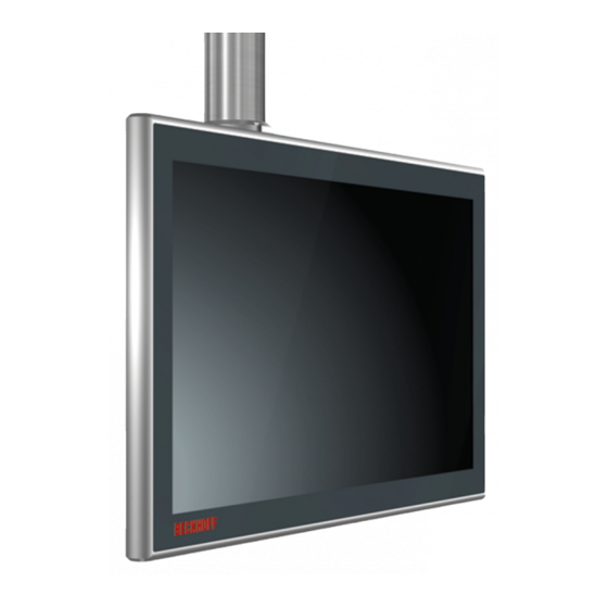
Product overview Product overview The Beckhoff Panel generation with industrial multi-touch display is designed for installation on the mounting arm. The devices offer suitable solutions for a variety of applications. The model variety ranges from different display sizes and formats to customer-specific models. -
Page 10: Fig. 2 Cp39Xx_Toolboard And Handle
Product overview Mechanical extensions You have the option of ordering the control panel with mechanical extensions such as a toolboard (1) or a handle (2) (see Fig. 2). The extensions are mounted ex factory. The following ordering options are available to you: Table 1: Ordering options for toolboards and handle Order identifier... -
Page 11: Structure
Display and touch screen glass Operating the control panel Connection block Control panel interfaces accessible Optional USB interface under screw Connection of peripheral devices Optional mounting arm adapter Beckhoff adapter for installation on the mounting arm tube from below CP39xx Version: 3.6... -
Page 12: Cp39Xx-0000 Interface Description
The interfaces are freely accessible (see Fig. 4). Fig. 4: CP39xx-0000_connection block For the control panel with Beckhoff mounting arm adapter, the connections are located inside the adapter. You must first gain access to the interfaces. The procedure is the same, regardless of whether you have ordered the mounting arm adapter with upwards or downwards orientation. -
Page 13: Power Supply
The plug is included in the delivery. You can obtain a replacement plug from your Beckhoff Sales using the following ordering option: • C9900-P916: power supply connector for CP39xx, round connector IP65 with strain relief for the... -
Page 14: Dvi Extended Input
Product overview 3.2.2 DVI Extended input The CP39xx-0000 Control Panel has a DVI Extended input (X102). It is used to transmit the graphics signal from the industrial PC to the control panel. The graphics signal is transferred directly via a DVI cable over a distance of 50 m max. Such a cable length leads to strong distortion of the graphics signal on arrival at the control panel. -
Page 15: Usb Extended Input
Product overview 3.2.3 USB Extended input The CP39xx-0000 Control Panel has a USB Extended input (X103). The control panel is connected to the CU8801 USB-to-USB extended converter box via the interface. To realize a distance of 50 m without hubs, USB Extended converts the USB signal so that it can be transmitted via a 50 m CAT 5 cable. -
Page 16: Cp39Xx-0010 Interface Description
The interfaces are freely accessible (see Fig. 9). Fig. 9: CP39xx-0010_connection block For the control panel with Beckhoff mounting arm adapter, the connections are located inside the adapter. You must first gain access to the interfaces. The procedure is the same, regardless of whether you have ordered the mounting arm adapter with upwards or downwards orientation. -
Page 17: Power Supply
The plug is included in the delivery. You can obtain a replacement plug from your Beckhoff Sales using the following ordering option: • C9900-P916: power supply connector for CP39xx, round connector IP65 with strain relief for the external supply cable 3.3.2... -
Page 18: Fig. 13: Cp39Xx-0010_Cp-Link 4
Product overview CP-Link 4 is available as a Two Cable Display Link on an industrial PC with PCIe module. The control panel can be connected directly to the industrial PC via the module. USB 2.0 (100 Mbit/s) and DVI are transmitted together via a CP-Link 4 cable. An additional power supply is required for CP39xx-0010 (see Fig. 13). 24 V 24 V CP-Link 4 (100 m) -
Page 19: Fig. 14 Cp39Xx-0010_Cp-Link 4, Cu8802-00X0
Product overview CP-Link 4 (100 m) CU8802-0000 0000 CP-Link 4 (100 m) CP-Link 4 (100 m) Fig. 14: CP39xx-0010_CP-Link 4, CU8802-00x0 When installing the CP39xx-0010 with the CU8803 transmitter box, the industrial PC is likewise connected to the transmitter box via USB and DP/DVI. The transmitter box is then connected to the control panel via the CP-Link 4 connection of the transmitter box using a CP-Link 4 cable. - Page 20 Product overview • CU8802-0001: DisplayPort to DVI cable included with box • CU8803-0000: DVI-to-DVI cable included in the box • CU8803-0001: DisplayPort to DVI cable included with box Version: 3.6 CP39xx...
-
Page 21: Optional Usb Interface
• USB (order identifier: C9900-E274) If you have ordered the device with a Beckhoff mounting arm adapter, the additional USB interface is located on the adapter. On a device without a mounting arm adapter, the interface is located at the side of the connection block. -
Page 22: Name Plate
Product overview Name plate The name plate provides information about the control panel equipment. The name plate shown here serves only as an example. xxxxxxxx Fig. 18: CP39xx_name plate Table 9: Key for CP39xx name plate Description Model: the last four digits indicate the product version. Serial number (BTN) Date of manufacture Display... -
Page 23: Connection Cables/Connection Kits
Product overview Connection cables/connection kits Different connection kits or connection cables are available, depending on the product version. 3.6.1 CP39xx-0000 connection kits The following connection kits are available for the CP39xx-0000: Table 10: CP39xx-0000 connection kits Connection kits Description C9900-K630 3 m connection kit for CP39xx-0000, consisting of: 3 m DVI cable, 3 m CAT-5 cable for USB-E-2.0, CU8801 USB-to-USB-E-2.0 converter for DIN rail mounting next to the PC and 1 m USB cable for connecting the USB-to- USB-E-2.0 converter to the PC... -
Page 24: Cp39Xx-0010 Connection Cable
Product overview 3.6.2 CP39xx-0010 connection cable The following connection cables are available for the CP39xx-0010: Table 11: CP39xx-0010 connection cable Connection cable Description C9900-K669 RJ45 connection cable CAT.6 , 1 m, one end with IP65 connector for Control Panel CP39xx-0010 or CPX39xx-0010 C9900-K667 RJ45 connection cable CAT.6 , 3 m, one end with IP65 connector for Control Panel... - Page 25 Product overview Connection cable Description C9900-K724 RJ45 connection cable CAT.6 , 3 m, one end with IP65 connector for Control Panel CP39xx-0010 or CPX39xx-0010, drag-chain suitable C9900-K704 RJ45 connection cable CAT.6 , 5 m, one end with IP65 connector for Control Panel CP39xx-0010 or CPX39xx-0010, drag-chain suitable C9900-K705 RJ45 connection cable CAT.6...
-
Page 26: Commissioning
Beckhoff protective film. The film provides short-term protection for a few days. You can either order a Beckhoff protective film individually and fit it yourself retrospectively, or you can order the film for fitting directly ex factory. -
Page 27: Transport And Unpacking
4. Check your delivery for completeness by comparing it with your order. 5. Check the contents for visible shipping damage. 6. In case of discrepancies between the package contents and the order, or in case of transport damage, please inform Beckhoff Service (see Chapter 9.1 Service and support). CP39xx Version: 3.6... -
Page 28: Mounting
In the basic configuration, there is a connection block with four M6 threaded holes on the rear side of the housing. This can be used to install the control panel on a mounting arm system. The control panel can optionally be ordered with the Beckhoff mounting arm adapter. The following ordering options are available: Table 12: Mounting arm adapter ordering options... -
Page 29: Fig. 19 Cp39Xx_Mounting Arm Adapter Options
Commissioning Fig. 19: CP39xx_Mounting arm adapter options For a control panel with push button extension, a cable channel between the panel and the mounting arm adapter is included in the ordering option (see Fig. 20). Fig. 20: CP39xx_cable channel The cables for the C9900-G02x push button extension run through the mounting arm tube into the mounting arm adapter and further through the cable channel into the push button extension. -
Page 30: Fig. 21 Cp39Xx_Opening The Cable Channel
Commissioning Fig. 21: CP39xx_opening the cable channel To open the push button extension, follow the steps below as shown in Figure 22: 1. Remove the seven Torx TX10 screws from the push button extension (section A). 2. Remove the cover of the push button extension (section B). Fig. 22: CP39xx_opening the push button extension Version: 3.6 CP39xx... -
Page 31: Installing The Mounting Arm Adapter
Commissioning 4.2.1 Installing the mounting arm adapter If you have chosen one of the two mounting arm adapter options C9900-M761 or C9900-M763, you must mount them yourself. The prerequisite for this is an adapter plate on the rear side of the device on which you can mount the selected mounting arm adapter. -
Page 32: Fig. 25 Cp39Xx_Mounting Arm Adapter Installed
Commissioning Fig. 25: CP39xx_Mounting arm adapter installed Version: 3.6 CP39xx... -
Page 33: Mounting Arm Tube Installation
If you have chosen a device with a mounting arm adapter, you must fit the mounting arm tube yourself. The procedure for fitting the mounting arm adapters with upwards or downwards orientation is the same. Among other tools you need a hook wrench for the installation. You can order this from your Beckhoff Sales using the following order identifier: •... -
Page 34: Connecting The Control Panel
Commissioning Connecting the control panel CAUTION Risk of electric shock Dangerous touch voltages can lead to electric shock. To avoid electric shock, adhere to the following points: • Never connect or disconnect the device cables during a thunderstorm. • Provide protective earthing for handling the device. To prepare the control panel for operation, you have to connect it. -
Page 35: Grounding The Control Panel
If the device is equipped with a connection block, the protective conductor connection is located directly next to the connections. For a device with a Beckhoff mounting arm adapter, the connection is located in the connection compartment (see Fig. 27). -
Page 36: Routing The Cables In The Mounting Arm Adapter
If you have ordered the control panel with one of the following Beckhoff mounting arm adapters installed ex factory, it is essential that you observe the cable routing shown (see Fig. 28) in order to avoid cable damage: •... -
Page 37: Fig. 29 Cp39Xx_Cable Routing Procedure
Commissioning 5. Rotate the strain relief rail back over the cable (section C). 6. Tighten the Torx TX20 screw again (section D). 7. Fasten the cable to the strain relief rail with cable ties. The figure shows the steps, taking the CP39xx-0000 as an example. The procedure is the same regardless of the product version. -
Page 38: Push Button Extension Cable Routing
M20 cable gland and the cable channel into the push button extension. Beckhoff takes care of the wiring of the C9900-G05x push button extension for you. Therefore you can order ready-to-use cables from Beckhoff Sales. For more detailed information on cable options and wiring diagram, refer to the C9900-G05x manual. -
Page 39: Connection Cables And Power Supply
Commissioning 4.3.4 Connection cables and power supply NOTE Incorrect connection procedure Incorrect procedure when connecting the cables and the power supply can cause hardware damage. • Follow the documented procedure for connecting the cables and the power supply. • Always connect all cables first and only then switch on the power supply. •... - Page 40 Commissioning • Voltage drop: 1.8 A * 0.475 Ohm = 0.85 V With a CP39xx-0010 with CP-Link 4 and CU8803 transmitter box, you only have to pay attention to the voltage on the supply line to the transmitter box. For more detailed information, please refer to the manual for the CU8803.
-
Page 41: Decommissioning
Decommissioning Decommissioning NOTE Hardware damage due to power supply A connected power supply can cause damage to the control panel during disassembly. • Disconnect the power supply from the device before starting to disassemble it. When taking the control panel out of operation, you must first disconnect the power supply and cables. You can then dismantle the device. -
Page 42: Fig. 34 Cp39Xx_Releasing The Strain Relief Rail
Decommissioning In the case of the CP39xx-0000 and CP39xx-0010, release all cables from the strain relief rail by following the steps below as shown in fig. 34: 1. Sever the cable ties. 2. Loosen the Torx TX20 screw of the strain relief rail (section A). 3. -
Page 43: Disassembly And Disposal
Decommissioning Disassembly and disposal Before you can remove the control panel from the mounting arm tube, you must first disconnect the power supply and the cables (see chapter 5.1 Disconnecting the power supply and cables [} 41]). Disassembly mounting arm tube NOTE Damage to property due to falling down If the control panel is suspended from the ceiling and you undo the slotted nut of the mounting arm adapter... - Page 44 Decommissioning When disposing of the control panel the national electronic waste regulations must be followed. Version: 3.6 CP39xx...
-
Page 45: Maintenance
Cleaning the front screen You can clean the front screen of the control panel during operation. In order to avoid inadvertent touch entries when doing this, you must first set the device to "Cleaning Mode" with the help of the Beckhoff Control Tool. -
Page 46: Fig. 37 Cp39Xx_Select "Cleaning Mode
5 and 120 seconds. Right-click the sun symbol again and click "Options". Now select the appropriate period (see Fig. 38). Fig. 38: CP39xx_Configuration "Cleaning Mode" Repair Only the vendor may repair the device. If a repair should be necessary, contact Beckhoff Service (see Chapter 9.1 Service and support). Version: 3.6 CP39xx... -
Page 47: Troubleshooting
No picture/backlight Problem with the cable connections CP39xx-0000: check DVI cable connection CP39xx-0010: 1. Check the cable connections 2. Check the CU880x diagnostic LEDs 3. Check the power supply Beckhoff recommends using Beckhoff connection cables and connection kits. CP39xx Version: 3.6... -
Page 48: Technical Data
Technical data Technical data Table 15: Technical data Product designation CP39xx-0000 Weights (with connection block/ CP3907: 1.8 kg with mounting arm adapter) CP3912: 3.4 kg / 4.2 kg CP3913: 3.1 kg / 3.9 kg CP3915: 3.9 kg / 4.7 kg CP3916: 4.5 kg / 5.3 kg CP3918: 5.5 kg / 6.3 kg CP3919: 6.1 kg / 6.9 kg CP3921: 6.6 kg / 7.4 kg CP3924: 7.6 kg / 8.4 kg... - Page 49 Technical data Product designation CP39xx-0010 Weights (with connection block/ CP3907: 1.8 kg with mounting arm adapter) CP3912: 3.4 kg / 4.2 kg CP3913: 3.1 kg / 3.9 kg CP3915: 3.9 kg / 4.7 kg CP3916: 4.5 kg / 5.3 kg CP3918: 5.5 kg / 6.3 kg CP3919: 6.1 kg / 6.9 kg CP3921: 6.6 kg / 7.4 kg CP3924: 7.6 kg / 8.4 kg Supply voltage 24 V DC (20.4 –...
-
Page 50: Appendix
33415 Verl Germany Phone: + 49 5246/963-0 email: info@beckhoff.de The addresses of the worldwide Beckhoff branches and agencies can be found on our website at http:// www.beckhoff.com/. You will also find further documentation for Beckhoff components there. Version: 3.6 CP39xx... -
Page 51: Approvals
Appendix Approvals The following table shows the approvals of the control panel according to the product version by connection type: Table 16: Approvals CP39xx Product version according to connection type Approvals CP39xx-0000 USB/DVI interface CE, EAC, UKCA, FCC CP39xx-0010 CP-Link 4 connection CE, EAC, UKCA, FCC You will find all other applicable approvals on the name plate of your device. - Page 52 List of figures List of figures Fig. 1 CP39xx_without and with push button extension................. Fig. 2 CP39xx_Toolboard and handle....................Fig. 3 CP39xx_Structure ........................Fig. 4 CP39xx-0000_connection block....................Fig. 5 CP39xx-0000_access to interfaces....................Fig. 6 CP39xx-0000_voltage socket pin numbering................Fig. 7 CP39xx-0000_DVI-Extended input pin numbering ..............
- Page 53 List of tables List of tables Table 1 Ordering options for toolboards and handle................. Table 2 CP39xx configuration key ......................Table 3 Voltage socket pin assignment ....................Table 4 DVI Extended interface pin assignment ..................Table 5 USB E input pin assignment ......................Table 6 Voltage socket pin assignment ....................
- Page 55 More Information: www.beckhoff.com/cp39xx Beckhoff Automation GmbH & Co. KG Hülshorstweg 20 33415 Verl Germany Phone: +49 5246 9630 info@beckhoff.com www.beckhoff.com...
Need help?
Do you have a question about the CP39 Series and is the answer not in the manual?
Questions and answers