Table of Contents
Advertisement
Quick Links
Advertisement
Chapters
Table of Contents

Related Manuals for Beckhoff CP32-2 Series


Summary of Contents for Beckhoff CP32-2 Series
- Page 1 Manual | EN CP32xx-2xxx Panel PC 2024-05-27 | Version: 1.9...
-
Page 3: Table Of Contents
Table of contents Table of contents 1 Notes on the documentation........................ 5 2 For your safety ............................ 6 Signal words............................ 6 Intended use ............................. 6 Fundamental safety instructions ....................... 7 Operator's obligation to exercise diligence.................. 7 Notes on information security...................... 8 3 Product overview ............................ - Page 4 Table of contents Version: 1.9 CP32xx-2xxx...
-
Page 5: Notes On The Documentation
EP1590927, EP1789857, EP1456722, EP2137893, DE102015105702 and similar applications and registrations in several other countries. ® EtherCAT is registered trademark and patented technology, licensed by Beckhoff Automation GmbH, Germany Copyright © Beckhoff Automation GmbH & Co. KG, Germany. The distribution and reproduction of this document as well as the use and communication of its contents without express authorization are prohibited. -
Page 6: For Your Safety
Exclusion of liability Beckhoff shall not be liable in the event of non-compliance with this documentation and thus the use of the devices outside the documented operating conditions. -
Page 7: Fundamental Safety Instructions
For your safety Fundamental safety instructions The following safety instructions must be observed when handling the device. Application conditions • Do not use the device under extreme environmental conditions. • Only use the device in hazardous areas if it is explicitly designed for this purpose. •... -
Page 8: Notes On Information Security
For your safety Notes on information security The products of Beckhoff Automation GmbH & Co. KG (Beckhoff), insofar as they can be accessed online, are equipped with security functions that support the secure operation of plants, systems, machines and networks. Despite the security functions, the creation, implementation and constant updating of a holistic security concept for the operation are necessary to protect the respective plant, system, machine and networks against cyber threats. -
Page 9: Product Overview
Product overview Product overview With the CP32xx series, you can use multitouch as a high-end panel PC directly in the field. The devices in the robust aluminum housing are designed for mounting arm installation. The connection cables are routed through the mounting arm. Thanks to its processors, you can use the panel PC for the following applications, among others: •... -
Page 10: Structure
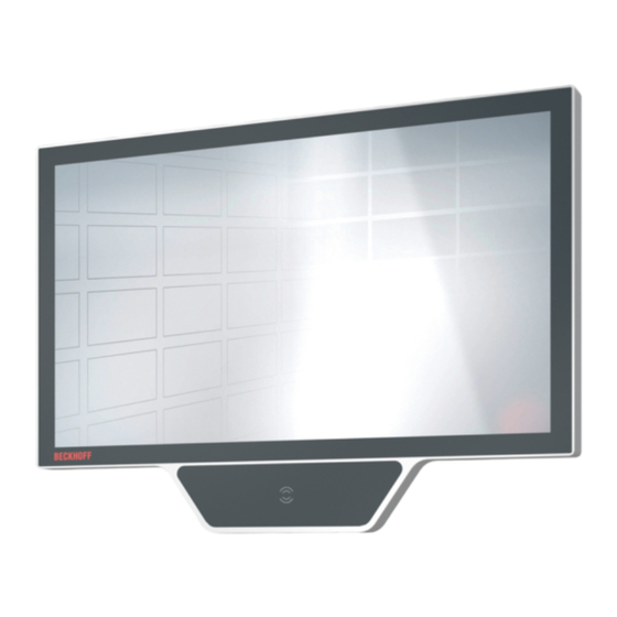
Product overview Structure Figure 1 shows the structure of the device as an example for all CP32xx variants. Fig. 1: Structure Table 1: Legend structure Component Description Example: Mounting arm C9900-M802 Mounting arm for mounting on ceiling Touch Screen Operation of the panel PC Heat sink Access to the motherboard Mounting arm adapter... -
Page 11: Interface Description
Product overview Interface description The panel PC has the following interfaces: • Power supply (XD01) • Ethernet (XF01, XF02) • USB (XG01-XG04) The interfaces are located at the bottom of the back of the housing. The push-pull built-in power socket for the power supply as well as one of the two push-pull built-in Ethernet sockets are freely accessible. -
Page 12: Power Supply
Product overview 3.2.1 Power supply The panel PC is supplied with a nominal voltage of 24 V. The connection of the power supply as well as the external wiring of the panel PC is carried out via a push- pull built-in power socket (XD01). There is a connection cable inside the column unit of the mounting arm. If the panel PC is used alone, this cable is intended for the power connection of the PC. -
Page 13: Ethernet Rj45
Product overview 3.2.2 Ethernet RJ45 The CP32xx has two Ethernet RJ45 interfaces (XF01, XF02) in the form of push-pull built-in Ethernet sockets. The 100Base-T and 1000Base-T Ethernet standards enable the connection of corresponding network components and data rates of 100/1000 Mbit/s. The required speed is selected automatically. There is a connection cable inside the column unit of the mounting arm. -
Page 14: Usb
Product overview 3.2.3 In the High Performance Class, the CP32xx has two USB 3.0 interfaces and two USB 2.0 interfaces. In the Smart Performance Class, the panel PC has one USB 3.0 interface and two USB 2.0 interfaces. The assignment of the interfaces varies depending on the device generation. The following table provides information about the assignment of the interfaces. -
Page 15: Name Plate
Product overview Name plate The name plate provides information about the equipment of your device. The name plate shown here serves only as an example. xxxxxxxx xxxxxxxxxxxxx xxxxxxxxxxxxx xxxxxxxxxxxxx Fig. 6: Name plate Table 6: Legend name plate Description Model: The last four digits indicate the device generation Serial number (BTN) Date of manufacture Mainboard... -
Page 16: Connection Cable
Product overview Connection cable Optionally, ready-made connecting cables for all connections are available in various lengths. You can order them using the following article descriptions: Table 7: Power supply connection cable Connection cable Power supply cable with IP65 plug C9900-K785 Power supply cable for CP32xx-2xxx, length 1.85 m, pre-assembled, push-pull power plug IP 65, other end HAN Modular C9900-K788 Power supply cable for CP32xx-2xxx, length 0.75 m, pre-assembled, push-pull... -
Page 17: Commissioning
You can either order a Beckhoff protective film individually and fit it yourself retrospectively, or you can order the film for fitting directly ex factory. Please refer to the price list for the available protective films according to the display size of your device. -
Page 18: Transport And Storage
4. Check your delivery for completeness by comparing it with your order. 5. Check the contents for visible shipping damage. 6. In case of discrepancies between the package contents and the order, or in case of transport damage, please inform Beckhoff Service (see Chapter Service and Support [} 47]). Version: 1.9 CP32xx-2xxx... -
Page 19: Mounting
Commissioning Mounting To align the device according to your requirements, four different mounting arms are available on which you can mount the device. The device is mounted on the mounting arm via a mounting arm adapter. Figure 7 shows the four available mounting arms for mounting on the ceiling (1), on the control cabinet (2), on the floor (3) and on the wall (4). -
Page 20: Fig. 8 Mounting Arm Adapter
Push button extension You have the option to order the additional C9900-M800 push button extension from your Beckhoff Sales department. For explanations of the push button extension, functions and mounting, refer to the associated C9900-M800 manual. -
Page 21: Dimensions
Commissioning 4.2.1 Dimensions The dimensions of the panel PC are for aligning the device on the mounting arm. All dimensions are in mm. Fig. 10 illustrates the dimensions of the 18.5-inch panel PC. 457,93 Fig. 10: Dimensions 18.5-inch Fig. 11 illustrates the dimensions of the 24-inch panel PC. 577,73 Fig. 11: Dimensions 24-inch CP32xx-2xxx... -
Page 22: Mounting Arm Installation
Commissioning 4.2.2 Mounting arm installation Observe the following points when mounting the panel PC on the mounting arm: • Position the panel PC such that reflections from light sources on the screen are avoided as far as possible. • For the correct installation height, use the position of the screen for guidance. This should always be optimally visible to the user. -
Page 23: Fig. 13: Mounting On Mounting Arm, Variant 2
Commissioning Fig. 13: Mounting on mounting arm, variant 2 If you have chosen the rotary adapter with lever in order to be able to rotate the device on the mounting arm, the installation is done in the same way as with the standard mounting arm adapter. CP32xx-2xxx Version: 1.9... -
Page 24: Mounting The Keyboard Shelf
Mounting the keyboard shelf You can mount a shelf for the keyboard and mouse below the PC. You can obtain the shelf from your Beckhoff sales department under the order identifier C9900-M801. You have three options for mounting the shelf (see Figure 14): •... -
Page 25: Mounting The Adapter Housing
Commissioning 4.2.4 Mounting the adapter housing You have the possibility to mount the C9900-M808 adapter housing for a Euchner EKS RFID reader on the panel PC. The shipment includes only the empty housing, without the Euchner EKS RFID reader. There are two drill holes on the back of the panel PC on the right for mounting the adapter housing. The housing is located to the left of the PC after installation. -
Page 26: Mounting Of Extensions
Commissioning 4.2.5 Mounting of extensions You have the option to mount additional extensions at the panel PC. These are the bracket for a signal lamp (C9900-M811) and the holder for an RFID card (C9900-M812). Signal lamp bracket You can mount a bracket for a signal lamp (C9900-M811) with an M12 connection socket on devices with mounting arms C9900-M803 and C9900-M804. -
Page 27: Fig. 19 Adhesive Strip Rfid Card
Commissioning 4. Press the holder with the adhesive strips (see Fig. 19) onto the front laminate. Fig. 19: Adhesive strip RFID card ð You have mounted the bracket. CP32xx-2xxx Version: 1.9... -
Page 28: Connecting The Panel Pc
Commissioning Connecting the Panel PC CAUTION Risk of electric shock Dangerous touch voltages can lead to electric shock. To avoid electric shock, observe the following: • Never connect or disconnect the device cables during a thunderstorm. • Provide protective earthing for handling the device. To make the device ready for operation, you have to connect it. -
Page 29: Fig. 20 Position Functional Earth Cable
Commissioning Fig. 20: Position functional earth cable The extensions shown are the following: • 1: Option C9900-M802 mounting arm for mounting on ceiling • 2: Option C9900-M803 stand for mounting on the control cabinet • 3: Option C9900-M804 stand for mounting on hall floors •... -
Page 30: Connecting Cables And Power Supply
Commissioning 4.3.2 Connecting cables and power supply NOTICE Incorrect connection procedure Incorrect procedure when connecting the cables and the power supply can cause hardware damage. • Follow the documented procedure for connecting the cables and the power supply. • Always connect the cables first and only then switch on the power supply. •... - Page 31 Commissioning Connecting the power supply Cables with the following maximum cable cross-sections must be used to connect the power supply: • 2.5 mm if using the panel PC without a mounting arm • 2.5 mm if using the panel PC on the mounting arms C9900-M802 and C900-M805; the plug is provided •...
-
Page 32: Switching The Panel Pc On And Off
When you switch on the PC for the first time, the optionally pre-installed operating system will be started. For any additional hardware you have connected, you have to install the drivers yourself afterwards. In addition, the Beckhoff Device Manager starts automatically. The Device Manager is a software from Beckhoff that supports you in configuring the PC. -
Page 33: Decommissioning
Decommissioning Decommissioning NOTICE Hardware damage due to power supply A connected power supply can cause damage to the device during disassembly. • Disconnect the power supply from the device before starting to disassemble it. As part of the decommissioning of the panel PC, you must first disconnect the power supply and cables. Afterwards, you can dismount the device from the mounting arm. -
Page 34: Disassembly And Disposal
Decommissioning Disassembly and disposal To be able to dismount the panel PC from the mounting arm, you must first have disconnected the power supply and the cables (see Chapter Disconnecting the power supply and cables [} 33]). Dismounting from the mounting arm Depending on the selected mounting arm on which you mounted the device, the procedure for dismounting is different. - Page 35 Decommissioning Dismounting the keyboard shelf To dismount the keyboard shelf, depending on the mounting option selected, you must either remove the Torx TX25 screws from the holes on the bottom of the PC or the push button extension, or remove the TX25 screws from the mounting plate.
-
Page 36: Maintenance
You can clean the front screen of the device during operation. In order to avoid inadvertent touch entries when doing this, you must first set the device to "Cleaning Mode" with the help of the Beckhoff Control Tool. Also make sure that you not only clean the display area, but also the edge of the glass pane. Impurities in... -
Page 37: Fig. 24 Select "Cleaning Mode
Maintenance The Beckhoff Control Tool does not start automatically when the device starts up. Proceed as follows to activate the "Cleaning Mode" of the Beckhoff Control Tool: 1. Go to the Beckhoff Control Tool to start it. ð When the tool is started, a small sun symbol appears in the taskbar. -
Page 38: Table 10 Device Component Replacement Recommendations
NOTICE Use of incorrect spare parts The use of spare parts not ordered from Beckhoff Service can lead to unsafe and faulty operation. • Only use spare parts that you have ordered from Beckhoff Service. Beckhoff devices are manufactured from components of the highest quality and robustness. They are selected and tested for best interoperability, long-term availability and reliable function under the specified environmental conditions. - Page 39 Maintenance • ESD-compatible work surfaces such as tables and shelves; • Wrist grounding strap, especially for sedentary activities; • grounded and electrostatically dissipating equipment and operating materials (e.g. tools) within the ESD protection zone. If it is not possible to create an ESD protection zone, you can still protect the device against ESD damage. For example, the following measures can be used: •...
-
Page 40: Access To Device Components
Maintenance 6.2.1 Access to device components In order to be able to exchange the storage media, the battery or the fan, you must first gain access to these device components. Access to storage media Access is gained to the storage media from the back of the panel PC. The storage media are located behind the lateral cover flap. -
Page 41: Fig. 28 Battery And Fans
Maintenance Fig. 28: Battery and fans CP32xx-2xxx Version: 1.9... -
Page 42: Replacing The Storage Media
If you want to exchange a storage medium according to Beckhoff's recommendation, you must copy the data from the old to the new storage medium. You can use the Beckhoff Service Tool (BST) for this purpose. BST is a graphical backup and restore program for PCs with a Windows operating system. You can create an image of your operating system and use it to back up the operating system. -
Page 43: Replacing The Battery
Replace the battery with R/C (BBCV2), order number RC2032, nominal voltage 3 V. Using any other battery may cause fire or explosion. • Only replace the battery with a replacement battery from Beckhoff Service. • When replacing the battery, make sure that the polarity is correct. -
Page 44: Replacing The Fan
The device may be damaged if the wrong type of fan is installed. • Only replace the fans with replacement fans from Beckhoff Service. The fans ensure optimal cooling of the device. Order replacement fans only from Beckhoff. Please get in touch with your Beckhoff sales contact. -
Page 45: Troubleshooting
No function of the panel PC No power supply to the panel PC Check the power supply cable Other cause Call Beckhoff Service The panel PC does not boot fully BIOS setup settings are incorrect Check BIOS setup settings (load... -
Page 46: Technical Data
CP3224: approx. 10 kg Supply voltage 22-30 V (24 V power supply unit) Power consumption Data sheet for calculating power consumption and power loss in the download finder - Data sheets: https://www.beckhoff.com/en-en/support/download-finder/search- result/?download_group=691754572 Protection rating IP65 Vibration resistance (sinusoidal EN 60068-2-6: 10 ... 58 Hz: 0.035 mm vibration) 58 ... -
Page 47: Appendix
33415 Verl Germany Phone: + 49 5246/963-0 email: info@beckhoff.de The addresses of the worldwide Beckhoff branches and agencies can be found on our website at http:// www.beckhoff.com/. You will also find further documentation for Beckhoff components there. CP32xx-2xxx Version: 1.9... -
Page 48: Approvals
Appendix Approvals Your device has at least the following approvals: • CE • EAC • UKCA • FCC You will find all other applicable approvals on the name plate of your device. FCC approvals for the United States of America FCC: Federal Communications Commission Radio Frequency Interference Statement This device was tested and complies with the limits for a digital device of class A, according part 15 of the FCC regulations. - Page 49 List of figures List of figures Fig. 1 Structure............................Fig. 2 Access to interfaces ........................Fig. 3 Voltage socket pin numbering...................... Fig. 4 Ethernet interface pin numbering ....................Fig. 5 USB interface pin numbering ....................... Fig. 6 Name plate........................... Fig. 7 Mounting arms ..........................
- Page 50 List of tables List of tables Table 1 Legend structure .......................... Table 2 Voltage socket pin assignment ....................Table 3 Ethernet interface pin assignment....................Table 4 Assignment USB interfaces ......................Table 5 USB interface pin assignment...................... Table 6 Legend name plate ........................Table 7 Power supply connection cable....................
- Page 52 Beckhoff Automation GmbH & Co. KG Hülshorstweg 20 33415 Verl Germany Phone: +49 5246 9630 info@beckhoff.com www.beckhoff.com...
Need help?
Do you have a question about the CP32-2 Series and is the answer not in the manual?
Questions and answers