Table of Contents
Advertisement
Quick Links
Advertisement
Chapters
Table of Contents

Subscribe to Our Youtube Channel
Related Manuals for Beckhoff CP32 1600 Series


Summary of Contents for Beckhoff CP32 1600 Series
- Page 1 Manual | EN CP32xx-1600 Panel PC 2024-03-20 | Version: 2.0...
-
Page 3: Table Of Contents
Grounding the Panel PC .................... 35 4.3.2 Connecting cables and power supply ................ 37 Switching the Panel PC on and off.................... 39 5 Beckhoff Device Manager ........................ 41 6 Decommissioning ........................... 43 Disconnecting the power supply and cables ................... 43 Disassembly and disposal....................... 44 7 Maintenance ............................ 46... - Page 4 Table of contents 9 Technical data ............................ 54 10 Appendix .............................. 55 10.1 Service and support ........................ 55 10.2 Approvals ............................ 56 Version: 2.0 CP32xx-1600...
-
Page 5: Notes On The Documentation
EP1590927, EP1789857, EP1456722, EP2137893, DE102015105702 and similar applications and registrations in several other countries. ® EtherCAT is registered trademark and patented technology, licensed by Beckhoff Automation GmbH, Germany Copyright © Beckhoff Automation GmbH & Co. KG, Germany. The distribution and reproduction of this document as well as the use and communication of its contents without express authorization are prohibited. -
Page 6: For Your Safety
Exclusion of liability Beckhoff shall not be liable in the event of non-compliance with this documentation and thus the use of the devices outside the documented operating conditions. -
Page 7: Fundamental Safety Instructions
For your safety Fundamental safety instructions The following safety instructions must be observed when handling the device. Application conditions • Do not use the device under extreme environmental conditions. • Only use the device in hazardous areas if it is explicitly designed for this purpose. •... -
Page 8: Notes On Information Security
For your safety Notes on information security The products of Beckhoff Automation GmbH & Co. KG (Beckhoff), insofar as they can be accessed online, are equipped with security functions that support the secure operation of plants, systems, machines and networks. Despite the security functions, the creation, implementation and constant updating of a holistic security concept for the operation are necessary to protect the respective plant, system, machine and networks against cyber threats. -
Page 9: Product Overview
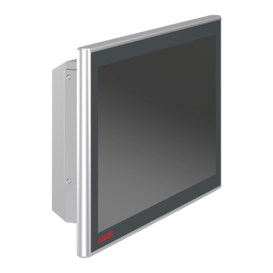
Product overview Product overview With the CP32xx-1600 series you can use multi-touch directly in the field. The devices in the robust aluminum housing are designed for mounting arm installation. Thanks to its processors, you can use the panel PC for the following applications, among others: •... -
Page 10: Fig. 1 Without And With Push Button Extension
Product overview Fig. 1: Without and with push button extension Version: 2.0 CP32xx-1600... -
Page 11: Structure
Product overview Structure Fig. 2: Structure Table 1: Legend for CP32xx-1600 configuration Component Description Display and touch screen glass Operation of the panel PC Battery and storage media cover Access to battery and storage media Extension plate with USB interface Additional USB interface with up to two further optional USB interfaces Connection compartment Access to interfaces... -
Page 12: Interface Description
The main supply voltage is applied between pins 5 (0 V) and 6 (24 V). If the panel PC is equipped with an integrated uninterruptible power supply (UPS), an external battery can additionally be connected to PIN 1 and PIN 2. The Beckhoff option C9900-U330 is available for this purpose. Version: 2.0... -
Page 13: Fig. 5 Voltage Socket Pin Numbering
Product overview X101 Fig. 5: Voltage socket pin numbering Table 2: Wiring with 8-core cable Core Sig- Description - BAT Negative pole of the battery pack Positive pole of the battery pack not used yellow/green Protective earth 24 V supply voltage, negative pole 24 V supply voltage, positive pole 24 V Input PC-ON... -
Page 14: Ethernet Rj45
Product overview 3.2.2 Ethernet RJ45 The basic version of the panel PC has an Ethernet RJ45 interface in the form of a push-pull built-in socket. The 100Base-T and 1000Base-T Ethernet standards enable the connection of corresponding network components and data rates of 100/1000 Mbit/s. The required speed is selected automatically. The cable is routed through the mounting arm adapter. -
Page 15: Usb
Product overview 3.2.3 The panel PC has a USB 3.0 interface according to IP65. This is used to connect peripheral devices with USB connection. The interface is located behind a screw cap. It supplies 900 mA current and is electronically fused. -
Page 16: Optional Interfaces
Product overview Optional interfaces You can extend the panel PC beyond the basic configuration by additional interfaces. Extension connection compartment Depending on the product version, different ordering options are available to add interfaces to the connection compartment: Table 6: Ordering options by product version Product version Ordering option CP32xx-1600-0020... -
Page 17: Fig. 8 Access Usb Interface
Product overview Any interfaces that are ordered are installed ex factory. You can also order the panel PC without interfaces in the extension plate. With the following ordering option, the PC is only equipped with a blank cover: • C9900-E330: CP32xx-16xx-00x0 without 1-port USB 3.0 socket below the PC housing Cover device components You can order another interface option, which is located by the motherboard battery and storage device behind the cover:... -
Page 18: Ethernet Rj45
Product overview 3.3.1 Ethernet RJ45 The additional, optional Ethernet RJ45 interfaces in the form of push-pull built-in sockets enable the connection of appropriate network components with data rates of 100/1000 Mbit/s in accordance with the Ethernet standards 100Base-T and 1000Base-T. The required speed is selected automatically. The RJ45 connection technology with twisted-pair cables is used. -
Page 19: Rs232
Product overview 3.3.2 RS232 The optional RS232 interface includes an M12 socket. The interface provides an asynchronous, serial communication method defined in the RS232 standard. Fig. 11: RS232 interface pin numbering Table 8: RS232 pin assignment Signal Type Description Carrier recognized Signal in Receive Data Signal out Transmit Data... -
Page 20: Rs485
Product overview Table 10: RS422 standard configuration Function Status Echo Auto send Always send Auto receive Always receive Termination 3.3.4 RS485 The optional RS485 serial interface includes an electrically isolated M12 socket for serial data transmission. The channel features overvoltage protection. If an overvoltage occurs, the channel is switched off. 11 12 Fig. 13: RS485 interface pin numbering Table 11: RS485 pin assignment... -
Page 21: Fig. 14 Optional Usb Interface Pin Numbering
Product overview 1 2 3 4 Fig. 14: Optional USB interface pin numbering Table 13: USB interface pin assignment Connection Vbus StdA_SSRX - StdA_SSRX + GND_DRAIN StdA_SSTX - StdA_SSTX + For USB 2.0, only pins 1 to 4 are relevant. CP32xx-1600 Version: 2.0... -
Page 22: Name Plate
Product overview Name plate The name plate provides information about the panel PC equipment. The name plate shown here serves only as an example. xxxxxxxx xxxxxxxxxxxxx xxxxxxxxxxxxx Fig. 15: CP32xx-1600_name plate Table 14: Legend for CP32xx-1600 name plate Description Model Serial number (BTN) Date of manufacture Mainboard Main memory... -
Page 23: Connection Cable
Product overview Connection cable Optionally, ready-made connecting cables for all connections are available in various lengths. You can order them using the following article descriptions: Table 15: Power supply cable Connecting cable Power supply cable with IP65 plug C9900-K271 Power supply cable IP65 for CP32xx, CP37xx or CP72xx, length 5 m, pre- assembled, M23 socket, screwable, 8-wire, second end open C9900-K272 Power supply cable IP65 for CP32xx, CP37xx or CP72xx, length 10 m, pre-... -
Page 24: Commissioning
You can either order a Beckhoff protective film individually and fit it yourself retrospectively, or you can order the film for fitting directly ex factory. Please refer to the price list for the available protective films according to the display size of your device. - Page 25 4. Check your delivery for completeness by comparing it with your order. 5. Check the contents for visible shipping damage. 6. In case of discrepancies between the package contents and the order, or in case of transport damage, please inform Beckhoff Service (see Chapter 10.1 Service and Support). CP32xx-1600 Version: 2.0...
-
Page 26: Assembly
For more information on the mounting arm adapter, please refer to the corresponding data sheet. Installing the mounting arm adapter If you have chosen the above-mentioned mounting arm adapter from Beckhoff, you must decide before mounting whether you want to align the device upwards or downwards (see Fig. 17). -
Page 27: Dimensions
Commissioning Fig. 17: Orientation of the mounting arm adapter To fasten the mounting arm adapter to the panel PC, follow the steps below, shown in Fig. 18: 1. Remove the cover of the mounting arm adapter (section A). For the exact procedure see chapter 3.2 Interface description [} 12]. -
Page 28: Fig. 19 Cp32Xx-1600_Dimensions 15-Inch
Commissioning Fig. 19 shows the dimensions of the 15-inch Panel PC. 3x M5 - 6H 360,8 4x M6 - 6H 4x M6 - 6H Fig. 19: CP32xx-1600_dimensions 15-inch Fig. 20 shows the dimensions of the 15.6-inch Panel PC. 3x M5 - 6H 405,8 4x M6 - 6H 4x M6 - 6H... -
Page 29: Fig. 22 Cp3218-1600_Dimensions 18.5-Inch
Commissioning 3x M5 - 6H 471,8 4x M6 - 6H 4x M6 - 6H Fig. 22: CP3218-1600_dimensions 18.5-inch Fig. 23 shows the dimensions of the 18.5-inch Panel PC with push button extension. 471,8 4x M6 - 6H 4x M6 - 6H 33,5 Fig. 23: CP3218-1600_dimensions 18.5-inch push button extension Fig. -
Page 30: Fig. 25 Cp3221-1600_Dimensions 21.5-Inch
Commissioning 3x M5 - 6H 537,2 4x M6 - 6H 4x M6 - 6H Fig. 25: CP3221-1600_dimensions 21.5-inch Fig. 26 shows the dimensions of the 21.5-inch Panel PC with push button extension. 537,2 4x M6 - 6H 4x M6 - 6H 33,5 Fig. 26: CP3221-1600_dimensions 21.5-inch push button extension Fig. -
Page 31: Fig. 28 Cp3224-1600_Dimensions 24-Inch Push Button Extension
Commissioning 592,2 4x M6 - 6H 4x M6 - 6H 33,5 Fig. 28: CP3224-1600_dimensions 24-inch push button extension CP32xx-1600 Version: 2.0... -
Page 32: Installing The Mounting Arm Tube
Depending on whether you have oriented the mounting arm adapter upwards or downwards, the mounting arm tube has to be installed on the adapter in the same direction. Among other tools you need a hook wrench for the installation. You can order this from your Beckhoff Sales using the following order identifier: •... -
Page 33: Mounting Accessories
Commissioning 4.2.3 Mounting accessories You have the option of retrofitting extensions such as a handle, a toolboard or a cabinet dome to your panel PC. The following ordering options are available to you. Handle and toolboard Table 20: Ordering options for handle and toolboard Order identifier Version C9900-M361... -
Page 34: Fig. 31 Mounting Cabinet Dome
Commissioning ð You have now mounted the panel PC to the cabinet dome. Fig. 31: Mounting cabinet dome Version: 2.0 CP32xx-1600... -
Page 35: Connecting The Panel Pc
Commissioning Connecting the Panel PC CAUTION Risk of electric shock Dangerous touch voltages can lead to electric shock. To avoid electric shock, observe the following: • Never connect or disconnect the device cables during a thunderstorm. • Provide protective earthing for handling the device. To make the device ready for operation, you have to connect it. -
Page 36: Fig. 32 Grounding Bolt For Functional Earthing
Commissioning Fig. 32: Grounding bolt for functional earthing For information on how to access the connection compartment, refer to chapter 3.2 Interface description [} 12]. Another grounding bolt is located inside the mounting arm adapter (see Fig. 33). You must establish a low- resistance connection via this bolt. -
Page 37: Connecting Cables And Power Supply
VRLA-AGM You can use the UPS output of the power supply unit and connect a Beckhoff control panel as a second display. If the supply voltage fails and the panel PC is only supplied by the battery pack, the control panel remains in operation. -
Page 38: Fig. 34 Wiring Diagram C9900-U330
Commissioning Industrial PC power connector Battery Power 24 V 24 V DC L max = 10 m ext. switch 1,5 mm / AWG14 Power status UPS Output 24 V DC 24 V/3,4 Ah 30 V/9 A C9900-U330 battery pack Fig. 34: Wiring diagram C9900-U330 Version: 2.0 CP32xx-1600... -
Page 39: Switching The Panel Pc On And Off
When you switch on the PC for the first time, the optionally pre-installed operating system will be started. For any additional hardware you have connected, you have to install the drivers yourself afterwards. In addition, the Beckhoff Device Manager starts automatically. The Device Manager is a software from Beckhoff that supports you in configuring the PC. - Page 40 You then use the installation package to install the UPS software components. The UPS software components come with a detailed help function. Call up the help files either directly from the configuration register by clicking the Help button or start the file under Start > Programs > Beckhoff > UPS software components.
-
Page 41: Beckhoff Device Manager
• User name: Administrator • Password: 1 You also have the option of using the Beckhoff Device Manager to remotely configure the industrial PC via a web browser. More detailed information is available in the Beckhoff Device Manager manual. First start Beckhoff Device Manager When your industrial PC is booted for the first time, the Beckhoff Device Manager also starts automatically for the first time. -
Page 42: Fig. 36 Beckhoff Device Manager - Start Page
Secure passwords Strong passwords are an important prerequisite for a secure system. Beckhoff supplies the device images with standard user names and standard passwords for the operating system. It is imperative that you change these. Controllers are shipped without a password in the UEFI/BIOS setup. Beckhoff recommends assigning a password here as well. -
Page 43: Decommissioning
Decommissioning Decommissioning NOTICE Hardware damage due to power supply A connected power supply can cause damage to the device during disassembly. • Disconnect the power supply from the device before starting to disassemble it. As part of the decommissioning of the panel PC, you must first disconnect the power supply and cables. Afterwards, you can dismount the device from the mounting arm. -
Page 44: Disassembly And Disposal
Removing the mounting arm adapter If you have installed a Beckhoff mounting arm adapter on your panel PC, follow the steps below to remove it (see Fig. 37): 1. Remove the cover of the mounting arm adapter (section A). For the exact procedure see chapter 3.2 Interface description [} 12]. -
Page 45: Fig. 38 Cp32Xx-1600_Removing The Mounting Arm Adapter
Decommissioning Fig. 38: CP32xx-1600_removing the mounting arm adapter Disposal of the panel PC When disposing of the panel PC, be sure to observe the national electronic waste regulations. CP32xx-1600 Version: 2.0... -
Page 46: Maintenance
You can clean the front screen of the device during operation. In order to avoid inadvertent touch entries when doing this, you must first set the device to "Cleaning Mode" with the help of the Beckhoff Control Tool. Also make sure that you not only clean the display area, but also the edge of the glass pane. Impurities in the edge area or liquids that do not run down the glass pane as drops but as a long short-circuit bridge Version: 2.0... -
Page 47: Fig. 39 Select "Cleaning Mode
This unintentionally triggers a touch event at the edge of the touch screen, which can lead to incorrect operation. The Beckhoff Control Tool does not start automatically when the device starts up. Proceed as follows to activate the "Cleaning Mode" of the Beckhoff Control Tool: 1. -
Page 48: Table 22 Device Component Replacement Recommendations
Beckhoff therefore recommends replacing some of the components of the devices after the time after which predictions of the remaining service life of such components can no longer be reliably calculated. -
Page 49: Replacing The Battery
Replace the battery with R/C (BBCV2), order number RC2032, nominal voltage 3 V. Using any other battery may cause fire or explosion. • Only replace the battery with a replacement battery from Beckhoff Service. • When replacing the battery, make sure that the polarity is correct. -
Page 50: Fig. 42 Replacing The Battery
Maintenance Table 23: Technical data of the battery Battery type Electrical properties (at 20 °C) Dimensions Nominal voltage Nominal capac- Diameter Height Weight CR2032 3.0 V 225 mAh 20.0 mm 3.20 mm 3.1 g Chapter 7.2 Maintenance [} 47] shows how to access the battery. To change the battery, proceed as follows: 1. -
Page 51: Replacing The Storage Media
If you want to exchange a storage medium according to Beckhoff's recommendation, you must copy the data from the old to the new storage medium. You can use the Beckhoff Service Tool (BST) for this purpose. BST is a graphical backup and restore program for PCs with a Windows operating system. You can create an image of your operating system and use it to back up the operating system. -
Page 52: Fan Cartridge Replacement
The device may be damaged if the wrong type of fan is installed. • Only replace the fans with replacement fans from Beckhoff Service. The fans ensure optimal cooling of the device. Order replacement fans only from Beckhoff. Please get in touch with your Beckhoff sales contact. -
Page 53: Troubleshooting
No function of the panel PC No power supply to the panel PC Check the power supply cable Other cause Call Beckhoff Service The panel PC does not boot fully BIOS setup settings are incorrect Check BIOS setup settings (load... -
Page 54: Technical Data
CP3224: 12.3 kg Supply voltage 22-30 V (24 V power supply unit) Power consumption Data sheet for calculating power consumption and power loss in the download finder - Data sheets: http://www.beckhoff.com/downloadfinder Protection rating IP65 Vibration resistance (sinusoidal EN 60068-2-6: 10 to 58 Hz: 0.035 mm vibration) 58 to 500 Hz:... -
Page 55: 10 Appendix
33415 Verl Germany Phone: + 49 5246/963-0 email: info@beckhoff.de The addresses of the worldwide Beckhoff branches and agencies can be found on our website at http:// www.beckhoff.com/. You will also find further documentation for Beckhoff components there. CP32xx-1600 Version: 2.0... -
Page 56: Approvals
Appendix 10.2 Approvals Your device has at least the following approvals: • CE • EAC • UKCA • FCC You will find all other applicable approvals on the name plate of your device. FCC approvals for the United States of America FCC: Federal Communications Commission Radio Frequency Interference Statement This device was tested and complies with the limits for a digital device of class A, according part 15 of the FCC regulations. - Page 57 Fig. 33 Mounting arm adapter grounding bolt ..................Fig. 34 Wiring diagram C9900-U330 ....................... Fig. 35 Beckhoff Device Manager - Change passwords ................Fig. 36 Beckhoff Device Manager – Start page ..................Fig. 37 CP32xx-1600_removing the mounting arm tube................Fig. 38 CP32xx-1600_removing the mounting arm adapter ..............
- Page 58 List of tables List of tables Table 1 Legend for CP32xx-1600 configuration..................Table 2 Wiring with 8-core cable....................... Table 3 Wiring with C9900-K275/-K276/-K277 ..................Table 4 Ethernet interface pin assignment....................Table 5 USB interface pin assignment...................... Table 6 Ordering options by product version .................... Table 7 Ethernet interface pin assignment....................
- Page 60 More Information: www.beckhoff.com/cp32xx-1600 Beckhoff Automation GmbH & Co. KG Hülshorstweg 20 33415 Verl Germany Phone: +49 5246 9630 info@beckhoff.com www.beckhoff.com...
Need help?
Do you have a question about the CP32 1600 Series and is the answer not in the manual?
Questions and answers