
Related Manuals for Beckhoff CP6700-0001-00 0 Series


Summary of Contents for Beckhoff CP6700-0001-00 0 Series
- Page 1 Installation and Operating instructions for CP6700-0001-00x0/ CP6706-0001-00x0 „Economy“ Built-in Panel PC Version: 1.2 Date: 2023-3-30...
-
Page 3: Table Of Contents
Table of contents Table of contents 1 Foreword Notes on the Documentation 1.1.1 Liability Conditions 1.1.2 Trademarks 1.1.3 Patent Pending 1.1.4 Copyright 1.1.5 State at Delivery 1.1.6 Delivery conditions Description of safety symbols Basic safety measures Operator’s obligation to exercise diligence 1.4.1 National regulations 1.4.2... - Page 4 5 Troubleshooting 6 Assembly dimensions 7 Technical Data 8 Appendix Beckhoff Support and Service 8.1.1 Beckhoff branches and partner companies 8.1.2 Beckhoff company headquarters Approvals for USA and Canada FCC Approvals for the United States of America FCC Approval for Canada...
-
Page 5: Foreword
Modifications to hardware or software configurations other than those described in the documentation are not permitted, and nullify the liability of Beckhoff Automation GmbH & Co. KG. 1.1.6 Delivery conditions In addition, the general delivery conditions of the company Beckhoff Automation GmbH & Co. KG apply. CP6700-0001-00x0/ CP6706-0001-00x0... -
Page 6: Description Of Safety Symbols
Foreword 1.2 Description of safety symbols The following safety symbols are used in this operating manual. They are intended to alert the reader to the associated safety instructions. Acute risk of injury! If you do not adhere the safety advise adjoining this symbol, there is immediate danger to life and health of individuals! DANGER Risk of injury! -
Page 7: Basic Safety Measures
Foreword 1.3 Basic safety measures Before the Panel PC is switched off, software that is running must be properly closed. Otherwise it is possible that data on the storage medium is lost. Please read the section Switching the Panel PC on and off. -
Page 8: Operator's Obligation To Exercise Diligence
• the operation manual is in good condition and complete, and always available for reference at the location of the product. Do not open the housing of the Panel PC! For technical support contact Beckhoff Service. Note 1.4.1 National regulations Depending on the type of machine and plant in which the Panel PC is used, national regulations governing the controllers of such machines will apply, and must be observed by the operator. -
Page 9: Product Description
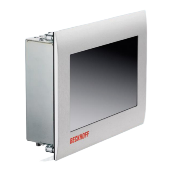
Product Description 2 Product Description 2.1 Product overview CP670x-0001-00x0 | “Economy” Panel PC With its highly integrated 3½-inch motherboard, the CP6700-0001-00x0 and CP6706-0001-00x0 built-in Panel PCs are ideally suited for use in machine construction and plant engineering, for example with the TwinCAT automation software under Windows Embedded Compact 7 or Windows Embedded Standard 7. -
Page 10: Appropriate Use
Product Description 2.2 Appropriate Use The CP670x built-in Panel PC is designed for installation in the front of a control cabinet or control housing. A steel plate housing with aluminum front contains a TFT display with touch screen. Risk of explosion! The Panel PC must not be used where there is a risk of explosion. -
Page 11: Interfaces
Product Description 2.4 Interfaces Protective X101 X103 X104 X107 X105 X109 Earthing (PE) Power LAN2 LAN1 X108 X106 DVI-I out 2.4.1 Power Supply (X101) The power supply for the Panel PC is established via the socket (X101), see also chapter Pin assignment of the connector. -
Page 12: Protective Earthing (Pe)
Product Description 2.4.5 Protective Earthing (PE) The low-resistance protective earthing of the Panel PC is established via the screw connection (PE). Protective Earthing (PE) The protective conductor connection must not be used for other potentials. “PE” and “0V” (24V system power supply) must be connected to the same potential (connected CAUTION in the control cabinet). -
Page 13: Access To The Battery And The Cfast Card Slot
Product Description 2.5 Access to the battery and the CFast card slot The battery and the CFast card slot are located behind a cover at the bottom side of the Panel PC: Torx screw (1) Torx screw (1) battery cover (2) CFast card slot For replacing the battery and installation of the CFast card first unloose the two Torx screws (1) with a srew driver T10. -
Page 14: Status-Leds
Product Description 2.6 Status-LEDs The Status-LEDs are located near the power supply connector (X101): X101 Description of the Status-LEDs: FB (Fieldbus): TwinCAT Stop blue TwinCAT Config blue/ red blinking TwinCAT Config (Fieldbus Error) green TwinCAT Run green/ red blinking TwinCAT Run (Fieldbus Error) HDD (Hard disk): Access to a memory device PWR (Power):... -
Page 15: Installation
4. Please keep the associated paperwork. It contains important information for handling the unit. 5. Check the contents for visible shipping damage. If you notice any shipping damage or inconsistencies between the contents and your order, you should notify Beckhoff Service. CP6700-0001-00x0/ CP6706-0001-00x0... -
Page 16: Installation In The Control Cabinet
Installation 3.2 Installation in the control cabinet The Panel PC CP670x is designed for mounting in control cabinets in machine and plant engineering applications. The ambient conditions specified for operation must be observed (see chapter Technical Data). 3.2.1 Preparation of the control cabinet The control cabinet wall must be prepared with the required mounting opening according to the Panel PC’s dimensions (see chapter Assembly... -
Page 17: Mounting Of The Panel Pc
Installation 3.2.3 Mounting of the Panel PC The Panel PC is installed in the cabinet wall with clamping levers. For the cutout dimension of the Panel PC see chapter Assembly dimensions, the wall thickness is between 1 mm and 5 mm. 1. -
Page 18: Power Supply Of The Industrial Pc
Installation 3.3 Power Supply of the Industrial PC The Industrial PC is fitted with a 24 V power supply unit. 3.3.1 Pin assignment of the connector The power supply and the external circuit of the Industrial PC are connected via the 4-pole plug connector (Phoenix DFMC 1,5/2-STF-3,5 BK –... -
Page 19: Configuration For Shutting Down The Pc
Installation 3.3.4 Configuration for shutting down the PC The connections for shutting down the Industrial PCs are established via the PC_ON input and the Power Status output. 3.3.5 PC_ON and Power Status functions • If the PC_ON input is connected to 24 V via a switch, the PC shuts down according to the rules. The PC_ON signal is inverted, i.e. -
Page 20: Connecting The Panel Pc
Installation 3.4 Connecting the Panel PC The mains plug must be disconnected Please read the documentation for the external devices prior to connecting them! Attention During thunderstorms, plug connector must neither be inserted nor removed! When disconnecting a plug connector, always handle it at the plug. Do not pull the cable! 3.4.1 Connecting cables The connections are located at the bottom of the Panel PC and are documented in the chapter Interfaces. -
Page 21: Operating Instructions
Operating Instructions 4 Operating Instructions 4.1 Switching the Panel PC on and off 4.1.1 Switching on The Panel PC does not have its own mains power switch. As soon as the power supply is switched on the Panel PC is activated. 4.1.2 Shutting down and switching off Control software such as is typically used on Industrial PCs permits various users to be given different rights. -
Page 22: Servicing And Maintenance
Operating Instructions 4.3 Servicing and maintenance 4.3.1 Cleaning Disconnect power supply Switch off the device and all connected devices, and disconnect the device from the power supply. DANGER The device can be cleaned with a soft, damp cleaning cloth. Do not use any aggressive cleaning materials, thinners, scouring material or hard objects that could cause scratches. -
Page 23: Troubleshooting
No power supply to the Panel PC Check power supply cable Cable not connected Correctly connect cable Call Beckhoff Service Panel PC boots, software starts, but Cause of the fault is either in the Call the manufacturer of the control does not operate correctly... -
Page 24: Assembly Dimensions
Assembly dimensions 6 Assembly dimensions CP6700-0001-00x0 Notice mounting orientation The assembly of the unit must take place with the orientation diagrammed here. Warning All dimensions are in mm. front view side view rear view with cut out CP6700-0001-00x0/ CP6706-0001-00x0... - Page 25 Assembly dimensions CP6706-0001-00x0 Einbaulage beachten Die Montage des Gerätes muss mit der dargestellten Ausrichtung erfolgen. Achtung All dimensions are in mm. front view left view rear view with cut out front view CP6700-0001-00x0/ CP6706-0001-00x0...
-
Page 26: Technical Data
Technical Data 7 Technical Data Risk of explosion! Do not use the Panel PC in areas of explosive hazard! Danger Pixel errors Pixel errors in the TFT display are production-caused and represent no complaint- reason! Note Anomalies of the Touchscreen Anomalies of the touchscreen sensor are production-caused and represent no complaint-reason! Note... -
Page 27: Appendix
Please contact your Beckhoff branch office or partner company for local support and service on Beckhoff products! The contact addresses for your country can be found in the list of Beckhoff branches and partner companies: www.beckhoff.com. You will also find further documentation for Beckhoff components there. -
Page 28: Approvals For Usa And Canada
Appendix 8.2 Approvals for USA and Canada 8.3 FCC Approvals for the United States of America FCC: Federal Communications Commission Radio Frequency Interference Statement This equipment has been tested and found to comply with the limits for a Class A digital device, pursuant to Part 15 of the FCC Rules.
Need help?
Do you have a question about the CP6700-0001-00 0 Series and is the answer not in the manual?
Questions and answers