Table of Contents
Advertisement
Quick Links
Advertisement
Table of Contents

Subscribe to Our Youtube Channel
Related Manuals for Loopcomm LP-8186C


Summary of Contents for Loopcomm LP-8186C
- Page 1 User’s Manual of WLAN Board band router USER MANUAL 1.0.0 © 2009...
- Page 2 This equipment has been tested and found to comply with the limits for a Class B digital device, pursuant to Part 15 of the FCC Rules. These limits are designed to provide reasonable protection against harmful interference in a residential installation. This equipment generates, uses and can radiate radio frequency energy and, if not installed and used in accordance with the instructions, may cause harmful interference to radio communications.
-
Page 3: Table Of Contents
Terminology...............................4 Introduction................................6 Package contents............................6 Product Specifications ..........................6 Product Features............................8 Front Panel Description ..........................9 Rear Panel Description ..........................10 Installation................................10 Hardware Installation..........................10 Software Installation ..........................10 Software configuration............................. 11 Prepare your PC to configure the WLAN Broadband Router ..............11 Connect to the WLAN Broadband Router....................12 Management and configuration on the WLAN Broadband Router ............12 Status..............................12 Setup Wizard............................14... - Page 4 What is RTS (Request To Send) Threshold?....................54 What is Beacon Interval? .........................54 What is Preamble Type? ..........................54 What is SSID Broadcast?.........................54 What is Wi-Fi Protected Access (WPA)?....................54 What is WPA2? ............................54 What is 802.1x Authentication?.......................54 What is Temporal Key Integrity Protocol (TKIP)?..................55 What is Advanced Encryption Standard (AES)? ..................55 What is Inter-Access Point Protocol (IAPP)? ..................55 What is Wireless Distribution System (WDS)? ..................55...
-
Page 5: Terminology
Terminology 3DES Triple Data Encryption Standard Advanced Encryption Standard ANSI American National Standards Institute Access Point Complementary Code Keying CSMA/CA Carrier Sense Multiple Access/Collision Avoidance CSMA/CD Carrier Sense Multiple Access/Collision Detection DDNS Dynamic Domain Name Server Diffie-Hellman Algorithm DHCP Dynamic Host Configuration Protocol DSSS Direct Sequence Spread Spectrum Extensible Authentication Protocol... - Page 6 Wireless Distribution System Wired Equivalent Privacy WLAN Wireless Local Area Network Wi-Fi Protected Access...
-
Page 7: Introduction
Introduction The WLAN AP Router is IEEE 802.11b/g WLAN AP router solution; setting SOHO and enterprise standard for high performance, secure, manageable and reliable WLAN. This document describes the steps required for the initial IP address assignment and other WLAN router configuration. - Page 8 0°C ~ 55°C ambient temperature Operation Temperature -20% ~ 70% ambient temperature Storage Temperature 10% ~ 90% (Non-condensing) Humidity One antenna connector One RJ-45 port for WAN Four RJ-45 LAN ports Connector Reset to default button Power jack WPS button 12V/1A Power requirement...
-
Page 9: Product Features
Product Features Generic Router 802.11b/g compliant with 54Mbps high-speed data rate Operation modes: AP, AP client, Client, Bridge, WDS DHCP Server/Client Four Ethernet ports for broadband sharing Virtual DMZ, Port Forwarding Dynamic DNS TCP/UDP/ICMP/ARP protocol stack Firewall, URL/IP/Port/MAC filtering Wireless users access control Wireless security –... -
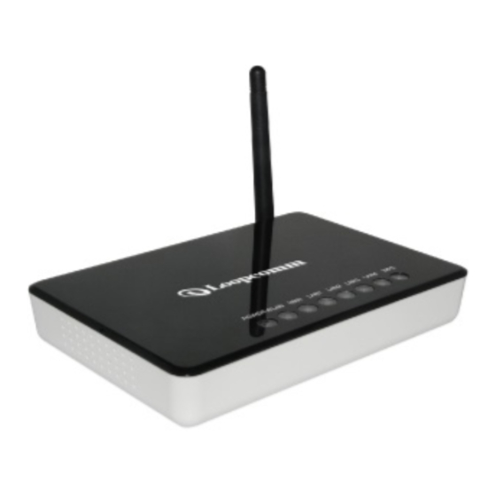
Page 10: Front Panel Description
Front Panel Description LED Indicator State Description 1. PWR LED The WLAN Broadband Router is powered on. The WLAN Broadband Router is powered off. 2. WLAN LED Flashing Data is transmitting or receiving on the antenna. No data is transmitting or receiving on the antenna. 3. -
Page 11: Rear Panel Description
Rear Panel Description Interfaces Description Antenna (Fixed / SMA) The Wireless LAN Antenna. Reset Push continually the reset button 5 ~ 10 seconds to reset the configuration parameters to factory defaults. Push continually the WPS button 5 ~ 10 seconds to enable the WPS feature. The RJ-45 sockets allow LAN connection through Category 5 cables. -
Page 12: Software Configuration
Notice: It will take about 50 seconds to complete the boot up sequence after powered on the WLAN Broadband Router; Power LED will be active, and after that the WLAN Activity LED will be flashing to show the WLAN interface is enabled and working now. -
Page 13: Connect To The Wlan Broadband Router
5. Select TCP/IP in Microsoft of Select Network Protocol dialog box then click OK button to install the TCP/IP protocol, it may need the Microsoft Windows CD to complete the installation. Close and go back to Network dialog box after the TCP/IP installation. 6. - Page 14 Item Description System Uptime It shows the duration since WLAN AP Router is powered on. Firmware version It shows the firmware version of WLAN AP Router. Wireless configuration Mode It shows wireless operation mode Band It shows the current wireless operating frequency. SSID It shows the SSID of this WLAN AP Router.
-
Page 15: Setup Wizard
BSSID It shows the BSSID address of the WLAN AP Router.BSSID is a six-byte address. Associated Clients It shows the number of connected clients (or stations,PCs). TCP/IP configuration IP Address It shows the IP address of LAN interfaces of WLAN AP Router. - Page 16 I. Operation Mode This page followed by Setup Wizard page to define the operation mode. II. Time Zone Setting This page is used to enable and configure NTP client.
- Page 17 III. LAN Interface Setup This page is used to configure local area network IP address and subnet mask. WAN Interface Setup This page is used to configure WAN access type.
- Page 18 V. Wireless Basic Settings This page is used to configure basic wireless parameters like Band, Mode, Network Type SSID, Channel Number, Enable Mac Clone(Single Ethernet Client). Wireless Security Setup This page is used to configure wireless security.
-
Page 20: Operation Mode
Operation Mode This page is used to configure which mode wireless broadband router acts. Item Description Gateway Traditional gateway configuration. It always connects internet via ADSL/Cable Modem. LAN interface, WAN interface, Wireless interface, NAT and Firewall modules are applied to this mode Bridge Each interface (LAN, WAN and Wireless) regards as bridge. - Page 21 Item Description Disable Wireless LAN Interface Click on to disable the wireless LAN data transmission. Band Click to select 2.4GHz(B) / 2.4GHz(G) / 2.4GHz(B+G) Mode Click to select the WLAN AP / Client / WDS / AP+WDS wireless mode. Network Type While Mode is selected to be Client.
-
Page 22: Wireless - Advanced Settings
Reset Click the Reset button to abort change and recover the previous configuration setting. Wireless - Advanced Settings These settings are only for more technically advanced users who have a sufficient knowledge about wireless LAN. These settings should not be changed unless you know what effect the changes will have on your WLAN Broadband Router. -
Page 23: Wireless - Security Setup
rate can be auto-select, 11M, 5.5M, 2M or 1Mbps. Preamble Type Click to select the Long Preamble or Short Preamble support on the wireless data packet transmission. Broadcast SSID Click to enable or disable the SSID broadcast function. IAPP Click to enable or disable the IAPP function. 802.11g Protection Protect 802.11b user. - Page 24 WPA Authentication While Encryption is selected to be WPA. Click to select the Mode WPA Authentication Mode with Enterprise (RADIUS) or Personal (Pre-Shared Key). WPA Cipher Suite Select the Cipher Suite for WPA encryption. WPA2 Cipher Suite Select the Cipher Suite for WPA2 encryption. Pre-Shared Key While Encryption is selected to be WPA.
- Page 25 WEP encryption key (secret key) length: Length Format 64-bit 128-bit ASCII 5 characters 13 characters 10 hexadecimal codes 26 hexadecimal codes WEP Key Setup Item Description Key Length Select the WEP shared secret key length from pull-down menu. The length can be chose between 64-bit and 128-bit (known as "WEP2") keys.
-
Page 26: Wireless - Access Control
previous configuration setting. Wireless - Access Control If you enable wireless access control, only those clients whose wireless MAC addresses are in the access control list will be able to connect to your Access Point. When this option is enabled, no wireless clients will be able to connect if the list contains no entries. -
Page 27: Wds Security Setup
removed from this WLAN Broadband Router. Delete All Click to delete all the registered clients from the access allowed list. Reset Click the Reset button to abort change and recover the previous configuration setting. WDS Security Setup Requirement: Set [Wireless]->[Basic Settings]->[Mode]->AP+WDS This page is used to configure the wireless security between APs. -
Page 28: Wds Settings
MAC Address It shows the MAC Address within WDS. Tx Packets It shows the statistic count of sent packets on the wireless LAN interface. Tx Errors It shows the statistic count of error sent packets on the Wireless LAN interface. Rx Packets It shows the statistic count of received packets on the wireless LAN interface. -
Page 29: Site Survey
Delete Selected Click to delete the selected clients that will be access right removed from this WLAN Broadband Router. Delete All Click to delete all the registered clients from the access allowed list. Reset Click the Reset button to abort change and recover the previous configuration setting. -
Page 30: Lan Interface Setup
Item Description Disable WPS Click on to disable the Wi-Fi Protected Setup function. WPS Status Show WPS status is Configured or UnConfigured. Self-PIN Number Fill in the PIN Number of AP to register the wireless distribution system access capability. Push Button Configuration The Start PBC button provides tool to scan the wireless network. If any Access Point or IBSS is found, you could connect it automatically when client join PBC mode. - Page 31 Item Description IP Address Fill in the IP address of LAN interfaces of this WLAN Access Point. Subnet Mask Fill in the subnet mask of LAN interfaces of this WLAN Access Point. Default Gateway Fill in the default gateway for LAN interfaces out going data packets.
-
Page 32: Wan Interface Setup
cloned Apply Changes Click the Apply Changes button to complete the new configuration setting. Reset Click the Reset button to abort change and recover the previous configuration setting. WAN Interface Setup This page is used to configure the parameters for wide area network that connects to the WAN port of your WLAN Broadband Router. - Page 33 and default gateway settings need to be done. IP Address If you select the Static IP support on WAN interface, fill in the IP address for it. Subnet Mask If you select the Static IP support on WAN interface, fill in the subnet mask for it. Default Gateway If you select the Static IP support on WAN interface, fill in the default gateway for WAN...
- Page 34 Item Description DHCP Client Click to select DHCP support on WAN interface for IP address assigned automatically from a DHCP server. Host Name Fill in the host name of Host Name. The default value is empty. MTU Size Fill in the mtu size of MTU Size. The default value is 1400.
- Page 35 DNS 2 Fill in the IP address of Domain Name Server DNS 3 Fill in the IP address of Domain Name Server Clone MAC Address Fill in the MAC address that is the MAC address to be cloned. Enable uPNP Click the checkbox to enable uPNP function.
- Page 36 Item Description PPPoE Click to select PPPoE support on WAN interface. There are user name, password, connection type and idle time settings need to be done. User Name If you select the PPPoE support on WAN interface, fill in the user name and password to login the PPPoE server.
- Page 37 default value is empty. Connection Type Select the connection type from pull-down menu. There are Continuous, Connect on Demand and Manual three types to select. Continuous connection type means to setup the connection through PPPoE protocol whenever this WLAN AP Router is powered on. Connect on Demand connection type means to setup the connection through PPPoE protocol whenever you send the data packets...
- Page 38 connection pass through. Enable L2TP pass through on VPN Click the checkbox to enable L2TP packet pass connection through. Apply Changes Click the Apply Changes button to complete the new configuration setting. Reset Click the Reset button to abort change and recover the previous configuration setting.
- Page 39 Item Description PPTP Allow user to make a tunnel with remote site directly to secure the data transmission among the connection. User can use embedded PPTP client supported by this router to make a VPN connection. Enable Dynamic Mode Click to select PPTP Dynamic support on WAN interface for IP address assigned automatically from a PPTP server.
- Page 40 IP Address If you select the PPTP support on WAN interface, fill in the IP address for it. Subnet Mask If you select the PPTP support on WAN interface, fill in the subnet mask for it. Gateway If you select the Static PPTP support on WAN interface, fill in the gateway for WAN interface out going data packets.
-
Page 41: Firewall - Port Filtering
connection through. Apply Changes Click the Apply Changes button to complete the new configuration setting. Reset Click the Reset button to abort change and recover the previous configuration setting. Note: PPTP Gateway Your ISP will provide you with the Gateway IP Address. If your LAN has a PPTP gateway, then enter that PPTP gateway IP address here. -
Page 42: Firewall - Ip Filtering
removed from the port-filtering list. Delete All Click to delete all the registered entries from the port-filtering list. Reset Click the Reset button to abort change and recover the previous configuration setting. Firewall - IP Filtering Entries in this table are used to restrict certain types of data packets from your local network to Internet through the Gateway. -
Page 43: Firewall - Mac Filtering
Reset Click the Reset button to abort change and recover the previous configuration setting. Firewall - MAC Filtering Entries in this table are used to restrict certain types of data packets from your local network to Internet through the Gateway. Use of such filters can be helpful in securing or restricting your local network. Item Description Enable MAC Filtering Click to enable the MAC filtering security function. -
Page 44: Firewall - Port Forwarding
Firewall - Port Forwarding Entries in this table allow you to automatically redirect common network services to a specific machine behind the NAT firewall. These settings are only necessary if you wish to host some sort of server like a web server or mail server on the private local network behind your Gateway's NAT firewall. -
Page 45: Firewall - Url Filtering
Firewall - URL Filtering URL Filtering is used to restrict users to access specific websites in internet. Item Description Enable URL Filtering Click to enable the URL Filtering function. URL Address Add one URL address. Apply Changes Click the Apply Changes button to save settings. Reset Click the Reset button to abort change and recover the previous configuration setting. -
Page 46: Management - Statistics
Item Description Enable DMZ Click to enable the DMZ function. DMZ Host IP Address To support DMZ in your firewall design, fill in the IP address of DMZ host that can be access from the WAN interface. Apply Changes Click the Apply Changes button to register the IP address of DMZ host. -
Page 47: Management - Ddns
It shows the statistic count of sent packets on the Sent Packets wireless LAN interface. It shows the statistic count of received packets on Received Packets the wireless LAN interface. Ethernet LAN It shows the statistic count of sent packets on the Sent Packets Ethernet LAN interface. -
Page 48: Management - Time Zone Setting
Domain Name To configure the Domain Name. User Name/Email Configure User Name, Email. Password/Key Configure Password, Key. Apply Change Click the Apply Changes button to save the enable DDNS service. Reset Click the Reset button to abort change and recover the previous configuration setting. -
Page 49: Management - Denial-Of-Service
Management - Denial-of-Service This page is used to enable and setup protection to prevent attack by hacker’s program. It provides more security for users. Item Description Enable DoS Prevention Click the checkbox to enable DoS prevention. Whole System Flood / Enable and setup prevention in details. -
Page 50: Management - Log
Clear ALL Click the checkbox to disable all prevention items. Apply Changes Click the Apply Changes button to save above settings. Management - Log This page is used to configure the remote log server and shown the current log. Item Description Enable Log Click the checkbox to enable log. -
Page 51: Management - Upgrade Firmware
Management - Upgrade Firmware This page allows you upgrade the Access Point firmware to new version. Please note, do not power off the device during the upload because it may crash the system. Item Description Select File Click the Browse button to select the new version of web firmware image file. -
Page 52: Management - Password Setup
Reset Settings to Click the Reset button to reset the configuration parameter Default to factory defaults. Management - Password Setup This page is used to set the account to access the web server of Access Point. Empty user name and password will disable the protection. -
Page 53: What Is Wireless Lan
To find your PC’s IP and MAC address, Open the Command program in the Microsoft Windows. Type in ipconfig /all then press the Enter button. Your PC’s IP address is the one entitled IP Address and your PC’s MAC address is the one entitled Physical Address. What is Wireless LAN? A wireless LAN (WLAN) is a network that allows access to Internet without the need for any wired connections to the user’s machine. -
Page 54: What Is Bssid
What is BSSID? A six-byte address that distinguishes a particular a particular access point from others. Also know as just SSID. Serves as a network ID or name. What is ESSID? The Extended Service Set ID (ESSID) is the name of the network you want to access. It is used to identify different wireless networks. -
Page 55: What Is Rts (Request To Send) Threshold
What is RTS (Request To Send) Threshold? The RTS threshold is the packet size at which packet transmission is governed by the RTS/CTS transaction. The IEEE 802.11-1997 standard allows for short packets to be transmitted without RTS/CTS transactions. Each station can have a different RTS threshold. -
Page 56: What Is Temporal Key Integrity Protocol (Tkip)
Beyond encapsulating EAP packets, the 802.1x standard also defines EAPOL messages that convey the shared key information critical for wireless security. What is Temporal Key Integrity Protocol (TKIP)? The Temporal Key Integrity Protocol, pronounced tee-kip, is part of the IEEE 802.11i encryption standard for wireless LANs. -
Page 57: What Is Ipsec
What is IPSEC? IPSEC is the abbreviation of IP Security. It is used to transferring data securely under VPN. What is WLAN Block Relay Between Clients? An Infrastructure Basic Service Set is a BSS with a component called an Access Point (AP). The access point provides a local relay function for the BSS. -
Page 58: Configuration Examples
Configuration examples Example one - PPPoE on the WAN Sales division of Company ABC likes to establish a WLAN network to support mobile communication on sales’ Notebook PCs. MIS engineer collects information and plans the WLAN Broadband Router implementation by the following configuration. - Page 59 2. Configure the LAN interface: Open LAN Interface Setup page, enter the IP Address “192.168.1.254”, Subnet Mask “255.255.255.0”, Default Gateway “0.0.0.0”, enable DHCP Server, DHCP client range “192.168.1.100” to “192.168.1.200”. Press button to confirm the configuration setting.
- Page 60 3. Configure the WLAN interface: Open WLAN Interface Setup page, enter the SSID “AP”, Channel Number “11”. Press button to confirm the configuration setting.
-
Page 61: Example Two - Fixed Ip On The Wan
Example two - fixed IP on the WAN Company ABC likes to establish a WLAN network to support mobile communication on all employees’ Notebook PCs. MIS engineer collects information and plans the WLAN Broadband Router implementation by the following configuration. WAN configuration:Fixed IP IP Address 192.168.2.254... - Page 62 2. Configure the LAN interface: Open LAN Interface Setup page, enter the IP Address “192.168.1.254”, Subnet Mask “255.255.255.0”, enable DHCP Server, DHCP client range “192.168.1.100” to “192.168.1.200”. Press button to confirm the configuration setting.
- Page 63 3. Configure the WLAN interface: Open WLAN Interface Setup page, enter the SSID “AP”, Channel Number “11”. Press button to confirm the configuration setting.
Need help?
Do you have a question about the LP-8186C and is the answer not in the manual?
Questions and answers