Samson 3271 Mounting And Operating Instructions
Hide thumbs
Also See for 3271:
- Original instructions manual (72 pages) ,
- Mounting and operating instructions (68 pages) ,
- Mounting and operating instruction (112 pages)

Subscribe to Our Youtube Channel
Related Manuals for Samson 3271


Summary of Contents for Samson 3271
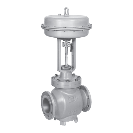
- Page 1 EB 8052 EN Translation of original instructions Type 3251 Valve with Type 3271 Actuator Type 3251 Valve · ANSI version In combination with an actuator, e.g. a Type 3271 or Type 3277 Pneumatic Actuator Edition July 2019...
- Page 2 Note on these mounting and operating instructions These mounting and operating instructions assist you in mounting and operating the device safely. The instructions are binding for handling SAMSON devices. The images shown in these instructions are for illustration purposes only. The actual product may vary.
-
Page 3: Table Of Contents
Contents Safety instructions and measures ..............1-1 Notes on possible severe personal injury ............1-4 Notes on possible personal injury ..............1-4 Notes on possible property damage .............1-6 Warnings on the device ................1-7 Markings on the device ................2-1 Valve nameplate ..................2-1 Actuator nameplate ..................2-2 Material numbers ..................2-2 Label when an adjustable packing is installed ..........2-2 Design and principle of operation ...............3-1... - Page 4 Removal ....................11-1 11.1 Removing the valve from the pipeline ............11-2 11.2 Removing the actuator from the valve ............11-2 Repairs ....................12-1 12.1 Returning devices to SAMSON ..............12-1 Disposal ....................13-1 Certificates ....................14-1 Appendix ....................15-1 15.1 Tightening torques, lubricants and tools ............15-1 15.2 Spare parts ....................15-1...
-
Page 5: Safety Instructions And Measures
SAMSON. SAMSON does not assume any liability for damage resulting from the failure to use the de- vice for its intended purpose or for damage caused by external forces or any other external factors. - Page 6 (see associated actuator documentation). When the valve is combined with a SAMSON Type 3271 or Type 3277 Pneumatic Actuator, the valve moves to a certain fail- safe position (see the 'Design and principle of operation' section) upon supply air or control signal failure.
- Page 7 The following documents apply in addition to these mounting and operating instructions: − Mounting and operating instructions for the mounted actuator, e.g. u EB 8310-X for Type 3271 or Type 3277 Pneumatic Actuator − Mounting and operating instructions for mounted valve accessories (positioner, solenoid valve etc.)
-
Page 8: Notes On Possible Severe Personal Injury
Safety instructions and measures 1.1 Notes on possible severe personal injury DANGER Risk of bursting in pressure equipment. Valves and pipelines are pressure equipment. Impermissible pressure or improper opening can lead to valve components bursting. Î Observe the maximum permissible pressure for valve and plant. Î... - Page 9 Risk of personal injury due to preloaded springs. Valves in combination with pneumatic actuators with preloaded springs are under ten- sion. These control valves with SAMSON pneumatic actuators can be identified by the long bolts protruding from the bottom of the actuator.
-
Page 10: Notes On Possible Property Damage
Parts that are too loose may cause leakage. Î Observe the specified tightening torques (u AB 0100). Risk of valve damage due to the use of unsuitable tools. Certain tools are required to work on the valve. Î Only use tools approved by SAMSON (u AB 0100). EB 8052 EN... -
Page 11: Warnings On The Device
The lubricants to be used depend on the valve material. Unsuitable lubricants may cor- rode and damage the valve surface. Î Only use lubricants approved by SAMSON (u AB 0100). Risk of contamination of the process medium through the use of unsuitable lubricant and/or contaminated tools and components. - Page 12 EB 8052 EN...
-
Page 13: Markings On The Device
Markings on the device 2 Markings on the device Note Fig. 2-1 and the inscription table list all pos- 2.1 Valve nameplate sible characteristics and options that may appear on a valve nameplate. Only the in- scriptions relevant to the ordered Type 3251 Valve actually appear on the nameplate. -
Page 14: Actuator Nameplate
Markings on the device 2.4 Label when an adjustable The nameplate (80) is affixed to the yoke of the valve (see Fig. 2-2). packing is installed An instructional label is affixed to the valve when an adjustable packing is installed (see Fig. 2-3). -
Page 15: Design And Principle Of Operation
Depending on how the compression springs The seat (4) and plug with plug stem (5) are are arranged in the SAMSON Type 3271 installed in the body (1). The plug stem is and Type 3277 Pneumatic Actuator, the connected to the actuator stem (A7) by the... - Page 16 Plug (with plug stem) Venting Travel indicator scale Threaded bushing Stem connector clamps (packing nut) Castellated nut Signal pressure Stem connector nut Actuator connection Fig. 3-1: Type 3251 Valve with Type 3271 Pneumatic Actuator (left) and Type 3277 Pneumatic Actu- ator (right) EB 8052 EN...
-
Page 17: Versions
The bypass line ensures that the plant does not need to be shut down for service In these instructions, the preferable combina- and repair work on the valve. tion with a SAMSON Type 3271 or Type 3277 Pneumatic Actuator is described. Insulation The pneumatic actuator (with or without... -
Page 18: Valve Accessories
See the 'Markings on the device' sec- Noise emission tion. SAMSON is unable to make general state- ments about noise emissions as they depend Note on the valve version, plant facilities and pro- More information is available in Data Sheet cess medium. - Page 19 Design and principle of operation Dimensions and weights Table 3-1 to Table 3-4 provide a summary of the dimensions and weights of the standard version of Type 3251 Valve. The lengths and heights in the dimension diagrams are shown on page 3-9. Dimensions in mm ·...
- Page 20 Design and principle of operation ½ 1½ Valve 11.61 11.61 11.61 16.46 1000 cm² 11.61 11.61 11.61 16.46 1400- 60 cm² 18.90 18.90 18.90 19.80 H8 for ac- 1400- – tuator 120 cm² 18.90 18.90 18.90 19.80 2800 cm² 18.90 18.90 18.90 19.80 2x2800 cm² 1.97 2.36 3.05...
- Page 21 Design and principle of operation Table 3-2: Dimensions of Type 3251 Valve, NPS 8 and larger Valve – 21.38 26.50 29.00 35.00 40.00 Class 150 On request 1016 22.38 27.88 30.50 36.50 41.62 Class 300 On request 1057 24.00 29.62 32.25 38.25 43.62 Length L Class 600...
- Page 22 Design and principle of operation Valve – 16.46 1000 cm² On request 16.46 1400- On request 60 cm² 19.80 19.80 25.59 25.59 25.59 25.59 H8 for 1400- actuator 120 cm² 3) 19.80 19.80 25.59 25.59 25.59 25.59 2800 cm² 3) 19.80 19.80 25.59 25.59 25.59 25.59 2x2800 cm²...
- Page 23 Design and principle of operation Dimensional drawings Type 3251 up to NPS 3 without foot Type 3251 in NPS 4 and larger with foot Table 3-3: Weights for standard version of Type 3251 up to DN 150 Valve ½ 1½ Class 150 Class 300 Valve Class 600 without actua- Class 900 1235 On re-...
- Page 24 The associated actuator documentation applies to actuators, e.g. for SAMSON pneumatic actuators: u T 8310-1 for Type 3271 or Type 3277 Pneumatic Actuators up to 750 cm² actuator area u T 8310-2 for Type 3271 Actuator with 1000 cm² actuator area and larger u T 8310-3 for Type 3271 Actuator with 1400-60 cm² actuator area...
-
Page 25: Shipment And On-Site Transport
Shipment and on-site transport 4 Shipment and on-site trans- Î Leave the control valve in its transport container or on the pallet to transport it port on site. The work described in this section is only to Î Do not remove the protective caps from be performed by personnel qualified for the the inlet and outlet until immediately be- assignment accordingly. -
Page 26: Transporting The Valve
Î Observe the valve's center of gravity. Î Secure the valve against tipping over or A swivel hoist can be screwed into turning. SAMSON actuators with a female thread on the top diaphragm case in place of the eyebolt (see associated actuator WARNING documentation). -
Page 27: Lifting The Valve
Shipment and on-site transport − Do not damage the corrosion protection Note (paint, surface coatings). Repair any Contact our after-sales service for the trans- damage immediately. portation temperatures of other valve ver- − Protect the piping and any mounted sions. valve accessories against damage. - Page 28 Shipment and on-site transport a) Version with flanges Lifting instructions − Use a hook with safety latch (see 1. Attach one sling to each flange of the Fig. 4-1) to secure the slings from slip- body and to the rigging equipment (e.g. ping during lifting and transporting.
-
Page 29: Storing The Valve
Elastomer, e.g. actuator diaphragm Î Avoid long storage times. − To keep elastomers in shape and to pre- Î Contact SAMSON in case of different vent cracking, do not bend them or hang storage conditions or long storage peri- them up. - Page 30 EB 8052 EN...
-
Page 31: Installation
–10 °C (14 °F) The work position for the control valve is the front view looking onto the operating con- Î Contact SAMSON if the mounting posi- trols (including valve accessories). tion is not as specified above. Plant operators must ensure that, after instal-... -
Page 32: Preparation For Installation
Installation 5.2 Preparation for installation Î Locate the vent plug on the opposite side to the work position of operating person- Before installation, make sure the following nel. conditions are met: Î During connection of valve accessories, − The valve is clean. make sure that they are easily accessible and can be operated safely from the −... -
Page 33: Assembly
Risk of valve damage due to the use of un- work. suitable tools. Î Flush the pipelines. Î Only use tools approved by SAMSON (u AB 0100). Note The plant operator is responsible for clean- ing the pipelines in the plant. -
Page 34: Mounting The Actuator Onto The Valve
Installation 5.3.1 Mounting the actuator 2x small V-ports onto the valve WARNING Risk of personal injury due to preloaded springs. Actuators with preloaded springs are under tension. They can be identified by the long bolts protruding from the bottom of the actu- ator. -
Page 35: Testing The Installed Valve
Installation a) Version with flanges 5.4 Testing the installed valve 1. Close the shut-off valves in the pipeline DANGER at the inlet and outlet of the plant section Risk of bursting due to incorrect opening of while the valve is being installed. pressurized equipment or components. -
Page 36: Leak Test
Installation cessories not fitted with noise-reducing fit- WARNING tings. Both can damage hearing. Risk of personal injury due to preloaded Î Wear hearing protection when working springs. near the valve. Actuators with preloaded springs are under tension. They can be identified by the long bolts protruding from the bottom of the actu- WARNING WARNING... -
Page 37: Travel Motion
Installation 5. Check the valve for leakage to the atmo- Î Open and close the valve, observing the sphere. movement of the actuator stem. 6. Depressurize the pipeline section and Î Apply the maximum and minimum con- valve. trol signals to check the end positions of the valve. - Page 38 EB 8052 EN...
-
Page 39: Start-Up
Start-up 6 Start-up Î Wear hearing protection when working near the valve. The work described in this section is only to be performed by personnel qualified for the assignment accordingly. WARNING WARNING Crush hazard arising from actuator and WARNING plug stem moving. Risk of burn injuries due to hot or cold com- Î... - Page 40 Start-up Before start-up or putting the valve back into operation, make sure the following condi- tions are met: − The valve is properly installed into the pipeline (see the 'Installation' section). − The leak and function tests have been completed successfully (see the 'Testing the installed valve' section).
-
Page 41: Operation
Operation 7 Operation Î Wear hearing protection when working near the valve. Immediately after completing start-up or put- ting the valve back into operation (see the 'Start-up' section), the valve is ready for use. WARNING WARNING Crush hazard arising from actuator and WARNING plug stem moving. -
Page 42: Working In Closed-Loop Operation
Operation 7.1 Working in closed-loop operation The handwheel of valves with actuators with a handwheel must be in the neutral position during normal closed-loop operation. 7.2 Working in manual mode Valves with actuators with a handwheel can be manually closed or opened in case of supply air failure. -
Page 43: Malfunctions
Malfunctions 8 Malfunctions 8.1 Troubleshooting Malfunction Possible reasons Recommended action Actuator and plug stem Actuator is blocked. Check attachment. does not move on de- Unblock the actuator. mand. WARNING! A blocked actuator or plug stem (e.g. due to seizing up after remaining in the same position for a long time) can suddenly start to move uncontrollably. -
Page 44: Emergency Action
Malfunctions Malfunction Possible reasons Recommended action The valve leaks to the Defective packing Replace packing (see the 'Servicing' section) or atmosphere (fugitive contact our after-sales service. emissions). Version with adjustable Adjust the packing (see information under 'Adjust- packing : packing not ing the packing' in the 'Testing the installed valve' 2) tightened correctly... -
Page 45: Servicing
− Mounting and operating instructions for components and process medium escaping the mounted actuator, e.g. u EB 8310-X under pressure. for Type 3271 or Type 3277 Pneumatic Î Do not loosen the screw of the test con- Actuator nection while the valve is pressurized. - Page 46 Risk of valve damage due to the use of un- Actuators with preloaded springs are under suitable tools. tension. They can be identified by the long Î Only use tools approved by SAMSON bolts protruding from the bottom of the actu- (u AB 0100). ator.
-
Page 47: Periodic Testing
Servicing 9.1 Periodic testing Note The control valve was checked by SAMSON Depending on the operating conditions, before it left the factory. check the valve at certain intervals to prevent − Certain test results (seat leakage and leak a possible failure before it can occur. Opera-... - Page 48 Servicing Inspection and testing Corrective action Check the test connection and bellows Put the control valve out of operation (see the 'Decommis- seal (if used) for external leakage. sioning' section). To repair the bellows section, contact our WARNING! Risk of personal injury due after-sales service (see the 'Repairs' section).
- Page 49 5 Plug (with plug stem) 17 Body gasket 7 Guide bushing 21 Insulating section 8 Threaded bushing 92 Castellated nut (packing nut) Fig. 9-1: Standard version of Type 3251 with Type 3271 Actuator (left) and Type 3251 in version with insulating section (right) EB 8052 EN...
-
Page 50: Preparing The Valve For Service Work
Servicing 9.2 Preparing the valve for − Replacing the seat and plug (see sec- tion 9.4.3) service work 9.3 Mounting the valve after 1. Lay out the necessary material and tools to have them ready for the service work. service work 2. -
Page 51: Replacing The Gasket
Servicing 9.4.1 Replacing the gasket crisscross pattern. Observe tightening torques. NOTICE b) Version with insulating sec- Risk of control valve damage due to incor- tion or bellows seal rect servicing. Î The gasket can only be replaced when 1. Undo the body nuts (14) gradually in a all the following conditions are met: crisscross pattern. - Page 52 Servicing − The valve does not have a balanced Version with V-port plug: place the plug. flange (2) onto the valve body, making − The valve does not have a bellows sure that the largest V-shaped port of the seal. V-port plug faces toward the valve outlet.
- Page 53 Servicing 8 Threaded bushing 11 Spring 12 Washer 16 Packing ring 19 Spacer Fig. 9-2: Standard packing: NPS ½ to 1½ (left) and NPS 2 to 4 (right) 4. Insert the red spacer ring (15.1) between 2. Undo the body nuts (14) gradually in a the threaded bushing (8) and retaining crisscross pattern.
- Page 54 Servicing 9. Apply a suitable lubricant to all the pack- making sure that the largest V-shaped ing parts and to the plug stem (5). port of the V-port plug faces toward the valve outlet. See the 'Mounting the actu- 10. Slide the plug with plug stem (5) into the ator onto the valve' section.
-
Page 55: Replacing The Seat And Plug
Servicing 9.4.3 Replacing the seat and 13. Firmly press the plug (5) into the seat (4). Fasten down the insulating section (21) plug with the body nuts (14). Tighten the nuts gradually in a crisscross pattern. Ob- NOTICE serve tightening torques. Risk of control valve damage due to incor- 14. - Page 56 Servicing a) Standard version 15. Place the flange (2) together with the plug stem and plug (5) onto the body 1. Unscrew the castellated nut (92) and lift (1). Version with V-port plug: place the the yoke (3) off the flange (2). flange (2) onto the valve body, making 2.
-
Page 57: Ordering Spare Parts And Operating Supplies
12. Screw in the seat (4). Observe tightening torques. Contact your nearest SAMSON subsidiary or SAMSON's After-sales Service for infor- 13. Apply a suitable lubricant to all the pack- mation on spare parts, lubricants and tools. ing parts and to the new plug stem (5). - Page 58 Servicing 9-14 EB 8052 EN...
-
Page 59: Decommissioning
Decommissioning 10 Decommissioning WARNING The work described in this section is only to Risk of personal injury due to pressurized be performed by personnel qualified for the components and process medium escaping assignment accordingly. under pressure. Î Do not loosen the screw of the test con- nection while the valve is pressurized. - Page 60 Decommissioning (e.g. due to seizing up after remaining in 2. Completely drain the pipelines and the same position for a long time), re- valve. lease any stored energy in the actuator 3. Disconnect and lock the pneumatic air (e.g. spring compression). See associat- supply to depressurize the actuator.
-
Page 61: Removal
Removal 11 Removal WARNING WARNING The work described in this section is only to Risk of personal injury due to residual pro- be performed by personnel qualified for the cess medium in the valve. assignment accordingly. While working on the valve, residual process medium can escape and, depending on its properties, may lead to personal injury, e.g. -
Page 62: Removing The Valve From The Pipeline
Removal 11.1 Removing the valve from the pipeline a) Version with flanges 1. Support the valve to hold it in place when separated from the pipeline (see the 'Shipment and on-site transport' sec- tion). 2. Unbolt the flange joint. 3. Remove the valve from the pipeline (see the 'Shipment and on-site transport' sec- tion). -
Page 63: Repairs
Further information on returned devices and Î Contact SAMSON's After-sales Service how they are handled can be found at for repair work. u www.samson.de > Service & Support > After Sales Service. 12.1 Returning devices to SAMSON Defective devices can be returned to SAMSON for repair. - Page 64 12-2 EB 8052 EN...
-
Page 65: Disposal
Disposal 13 Disposal Î Observe local, national and internation- al refuse regulations. Î Do not dispose of components, lubricants and hazardous substances together with your household waste. EB 8052 EN 13-1... - Page 66 13-2 EB 8052 EN...
-
Page 67: Certificates
Certificates 14 Certificates The declaration of conformity is provided on the next page: − Declaration of conformity in compliance with Pressure Equipment Directive 2014/68/EU on page 14-2. EB 8052 EN 14-1... - Page 68 Modul/Module H / N° CE-PED-H-SAM 001-13-DEU SAMSON erklärt in alleiniger Verantwortung für folgende Produkte/explaines in sole resposibility for the following products: Geräte/Devices Bauart/Series Typ/Type Ausführung/Version DIN, Gehäuse GG/Cast iron-Body ab/from DN150, Gehäuse GGG/Sph. gr. Durchgangsventil/Globe Valve 3241 iron-Body ab/from DN100, Fluide/Fluids G2, L1, L2 DIN/ANSI, Geh.
-
Page 69: Appendix
Appendix 15 Appendix 15.1 Tightening torques, lubricants and tools u AB 0100 for tools, tightening torques and lubricants 15.2 Spare parts 1 Body 29 Plug for version with 64 Gasket 2) bellows seal 2 Flange 65 Gasket 2) 30 Retaining washers 3 Yoke 80 Nameplate 32 Bolt 4 Seat... - Page 70 80 81 80 81 83 84 42/43 (DN 15...150) (NPS ½...6) 13 91 102/103 15-2 EB 8052 EN...
-
Page 71: After-Sales Service
You can reach our after-sales service at af- tersalesservice@samson.de. Addresses of SAMSON AG and its subsid- iaries The addresses of SAMSON AG, its subsid- iaries, representatives and service facilities worldwide can be found on our website (www.samson.de) or in all SAMSON prod- uct catalogs. - Page 72 15-4 EB 8052 EN...
- Page 76 EB 8052 EN SAMSON AKTIENGESELLSCHAFT Weismüllerstraße 3 · 60314 Frankfurt am Main, Germany Phone: +49 69 4009-0 · Fax: +49 69 4009-1507 samson@samson.de · www.samson.de...
Need help?
Do you have a question about the 3271 and is the answer not in the manual?
Questions and answers