
Related Manuals for Growatt MAX 80-150KTL3-X LV Series


Summary of Contents for Growatt MAX 80-150KTL3-X LV Series
- Page 1 编号:GR-UM-C -00 Installation & Operation Manual Guangdong Growatt New Energy Co., LTD No.28 Guangming Road, Shiyan Street, Bao'an District, Shenzhen, PR. China T: +86 0755 2747 1942 E: service@ginverter.com W: www.ginverter.com 1 / 56...
-
Page 2: Table Of Contents
编号:GR-UM-C -00 目录 1. Overview ............................. 5 1.1 Product Overview ........................5 1.2 Applicable Personnel ....................... 5 2. Safety Precautions ........................... 5 2.1 Safety Overview ......................... 5 2.2 Symbol Conventions ........................ 7 2.3 Lable Description ........................8 3. Product Introduction........................9 3.1 Appearance .......................... - Page 3 编号:GR-UM-C -00 5.1 Basic Installation Requirements ..................15 5.2 Installation Environment Requirements ................16 5.3 Moving Requirements ......................18 5.4 Wall Mount Bracket Installation ..................19 5.5 Installing The Inverter ......................20 6. Connecting Cable ........................... 21 6.1 Connection on AC side ......................21 6.2 Connection On DC Side ......................
- Page 4 编号:GR-UM-C -00 7.2.3 Fault mode ......................... 34 7.2.4 Off mode ........................34 7.3 LED Display ..........................34 8 Remote Data Monitoring ......................36 8.1 Remote Data Monitoring ..................... 36 8.1.1 Mobile phone APP(ShinePhone) remote monitoring ......... 36 8.2 Local Data Monitoring ......................39 8.2.1 Mobile phone app (Shinephone) Local Monitoring ........
-
Page 5: Overview
1.1 Product Overview This manual is aimed at providing sufficient information and installing instruction for consumers buying Shenzhen Growatt New Energy Co., Ltd (short as Growatt) MAX 80-150KTL3-X LV/MV Series solar inverters. Please read this manual carefully before using the MAX 80-150KTL3-X LV/MV series inverters and store the manual in a reachable place for an authorized technician. - Page 6 Installation: ●Before installation, please read through this manual, any damage cause by improper installation, Growatt reserve the right to disclaim any warranty. ●Ensure that the MAX is not connected to a power supply and is not power on before installation.
-
Page 7: Symbol Conventions
编号:GR-UM-C -00 Maintenance and replacement: ● Must be installed by trained and authorized electrical technician and accurately follow this manual. ● Please disconnect the DC and AC switch for at least five minutes, all the operations should be carried after power disconnection. -
Page 8: Lable Description
编号:GR-UM-C -00 Indicates potentially hazardous situation which, if not avoided, will result in minor or moderate injury. Indicates certain hazardous situation which, if not avoided, will Result in property damage. Reminds operator to read installation manual before operating or installing inverter. 2.3 Lable Description Symbol Name... -
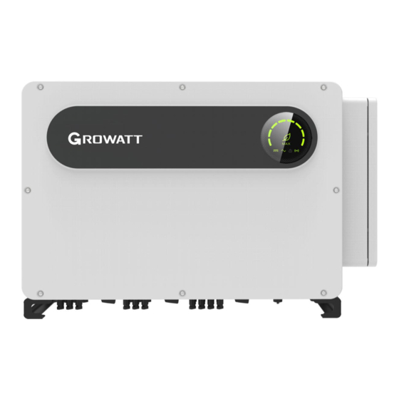
Page 9: Product Introduction
编号:GR-UM-C -00 3. Product Introduction 3.1 Appearance Front view: Fig 3.1 Bottom view (Termial): Fig 3.2 Mark Description Mark Description Front panel 9 / 56... -
Page 10: Basic Data
编号:GR-UM-C -00 PV terminal DC switch Breathing valve Safety ground screw USB interface COM interface Waterproof silicone Corner guard 3.2 Basic Data Size(mm) Weight Model (kg) Width Height Thickness MAX 80-150KTL3-X LV/MV Series Inverter MAX 80-150KTL3-X LV/MV 1100 Series Inverter with package 10 / 56... -
Page 11: Nameplate
编号:GR-UM-C -00 3.3 Nameplate Note: Other models of MAX 80-150KTL3-X LV/MV series share the same label design with MAX 125KTL3-X LV, only with different model name and parameters, detail parameter please refer to specification in Chapter 10. 3.4 Working Principle The MAX 80-150KTL3-X LV/MV series inverter works as follows: 1>The PV panels gather solar to generate DC power to inverter. -
Page 12: Inverter Storage
编号:GR-UM-C -00 On-grid connection system diagram: Fig 3.4 symbol Description symbol Description PV string Electric meter Inverter Gird 3.5 Inverter Storage 1>Do not unpack the inverter and store it in a ventilation dry place . 2>Keep the storage temperature at -30℃-+60℃ and humidity at 0-100%. 3>A maximum of four inverters with package can be stacked. -
Page 13: Afci Detection Function
编号:GR-UM-C -00 Fig 3.5 Fig 3.6 3.7 AFCI Detection Function AFCI (Arc Fault Circuit Interrupter) is a kind of circuit protection device, the main function is to prevent the fire caused by fault arc. The electrical insulation aging, breakage, loose connection, air breakdown caused by air humidity and so on, all of these may cause an electric spark, which is called arc. -
Page 14: Installation
编号:GR-UM-C -00 Package contents: Fig 4.1 Mark Descriptions Number Inverter Wall mount 14/14(7 MPPT) PV + terminal, PV- terminal 20/20(10MPPT) 14/14(7 MPPT) PV terminal metal core 20/20(10MPPT) Removal tool of PV terminals Installation manual Warranty card Rs485 terminal Removal handle(opt) Wall mount screw Ground screw Security screw... -
Page 15: Basic Installation Requirements
编号:GR-UM-C -00 under the inverter to protect its cover. 5.1 Basic Installation Requirements A. Ensure that the installation wall is solid enough to bear the inverter(Inverter weight please refer to installation manual Chapter3, 3.2 ). B. There must be enough installation space to fit the size of inverter. C. -
Page 16: Installation Environment Requirements
编号:GR-UM-C -00 Fig 5.2 J. Do not install inverter close to strong electromagnetic signal. K. Install the inverter out of children's reach. 5.2 Installation Environment Requirements A. Although the inverter's protection level is IP 66, to extent inverter lifespan you still need to avoid rain and snow, please refer to following drawings. - Page 17 编号:GR-UM-C -00 Fig 5.4 C. When you install multiple inverters on one surface, inverters should be installed as following drawing. Fig 5.5 D. Do not install inverter into an enclosed space like following drawing. Fig 5.6 17 / 56...
-
Page 18: Moving Requirements
编号:GR-UM-C -00 5.3 Moving Requirements •The inverter is heavy, please move it with care and keep balance to avoid personnel injury. •Do not place the inverter with its wiring and signal terminals at the bottom contacting with floor or any other object because the terminals are not designed to support the weight of inverter. -
Page 19: Wall Mount Bracket Installation
编号:GR-UM-C -00 5.4 Wall Mount Bracket Installation Before install the inverter you need install the wall mount bracket so that the inverter can be firmly installed on the wall. Wall mount plan: Fig 5.9 1>Use the wall mount plate as a template drill holes on the wall and put in expansion bolts. -
Page 20: Installing The Inverter
编号:GR-UM-C -00 Fig 5.11 Notice: Do not install inverter unless you have confirmed the wall mount plate has been firmly installed on the wall. 5.5 Installing The Inverter After the wall mount bracket has been firmly installed on the wall , put the inverter on that plate. -
Page 21: Connecting Cable
编号:GR-UM-C -00 Fig 5.13 Fig 5.14 6. Connecting Cable 6.1 Connection on AC side •Before electrical connection, please ensure the inverter DC switch is at "OFF” also disconnect AC switch, otherwise the high voltage from inverter may cause life risk. •Only trained authorized electrical technician can do the electric connection also please follow the connection procedures in this manual along with local country's regulations. - Page 22 编号:GR-UM-C -00 •Each inverter must install one AC breaker AC breaker is forbidden to share with other inverters. •It is forbidden to add load between inverter and breaker. Preparation before connection: 1>Disconnect inverter DC switch and AC breaker or switch. 2>When you lock the AC cable's screw, the torque force should be 100kgf·cm.
- Page 23 编号:GR-UM-C -00 MAX 150KTL3-X 70-240 Notice: The cable must be unbroken. If you connect the aluminum wire, please consult our technology. AC side connection steps: •If the cable is thick, after tightening the cable do not shake it and ensure the cable is well-connected and then start the inverter.
- Page 24 编号:GR-UM-C -00 Fig 6.2 Diagram of how to install a terminal: Fig 6.3 3>Put the water proof cover back to the inverter and fill the cover with fireproof mud, just as following drawing. Fig 6.4 • Must tighten the waterproof cover, otherwise there will be a risk of water leakage.
-
Page 25: Connection On Dc Side
If the inverter was damaged by higher maximum open circuit voltage (higher than 1100Vdc) product warranty will be forfeited and Growatt will not take any responsibility. •The inverter shall be used with IEC 61730 Class A rating PV module. -
Page 26: Connection Of Communication Cables
编号:GR-UM-C -00 Fig 6.5 5>Decide the length of peeling base on cable terminal, use the wire stripper to connect cable and terminal, and separately connect to specific connector. 6>Connect the positive and negative poles to inverter terminals, different inverter's maximum single string input current please refer to following table. Inverter model Max. - Page 27 编号:GR-UM-C -00 Inverters (Maximum 32 inverters) , the longest distance is 500 meters, high speed (Baud rate 38400) , the communication port as following. It is recommended to use shielded twisted pair for RS485 cable When a single inverter communicates, the shielding layer of the RS485 cable needs to be connected to the ground and can be connected to the PE of the inverter case;...
-
Page 28: Usb Port
编号:GR-UM-C -00 485-1 B1 REF/GEN 485-2 A1 485-1 Matching 485-2 B1 15/16 resistance Notice: When multiple inverters are connected in parallel or the transmission distance is long, The reason for this is to increase the matching resistance. Fig 6.7 6.3.2 USB port MAX 80-150KTL3-X LV/MV series inverter is configured with USB_A port ,can be connected to USB to WIFI module, Shine GPRS-X, Shine Wifi-X, Shine 4G-X, Shine Link-X, etc. -
Page 29: Connecting The Ground Cables
编号:GR-UM-C -00 6.4 Connecting The Ground Cables In this solar system all the unloaded metal components and cases should be connected to the ground. Single inverter need grounding over a PE point, multiple inverters need connect all the inverter PE cable and solar panels shelves to the same grounding point to achieve equipotential. - Page 30 编号:GR-UM-C -00 Fig 6.10 1)It is generally recommended to install lightning protection devices (such as lightning rods / lightning protection belts and down conductors) to prevent lightning from hitting the PV array. 2) Lightning protection devices and down-conductors and related equipment in photovoltaic systems (including photovoltaic panels, inverters, cables, power distribution equipment) should maintain a safe separation distance S.
-
Page 31: Commissioning
Click "Reset password" to enter the OSS account number and password. The distributor and installer can apply for the OSS account from Growatt. Click "Sign in" to set the password. After the setting is successful, you can start using it.) 3>Click top item “COM Address”;... - Page 32 编号:GR-UM-C -00 communication address of the inverter; 5> Set inverter com address; 6>Read inverter com address to ensure setting is successful; 32 / 56...
-
Page 33: Set Inverter Time And Date
编号:GR-UM-C -00 7.1.2 Set inverter time and date Method 1: Please refer to section 8.2.1 and login ShinePhone APP.Click "system time(45-50)"to set inverter time and date on the parameter setting page. Method 2: Please connect GPRS antenna to the inverter as section 6.3.3, when the inverter is powered on, connect the inverter to the server as section 8.1.2, then the inverter time will be updated automatically. -
Page 34: Fault Mode
编号:GR-UM-C -00 by the PV modules into AC power and supplies them to the grid. When the DC voltage is lower than 180Vdc, inverter will enter into “waiting” state and try to connect to the grid, at this status, inverter consume very small power to check the internal system status. - Page 35 编号:GR-UM-C -00 PV voltage reaches grid Green light is on PV voltage voltage indicator light PV voltage does not Light is not on reach the grid voltage Inverter is in the grid Green light is on state AC voltage No AC voltage Light is not on indicator light The green light flashes...
-
Page 36: Remote Data Monitoring
Note: 1.Make you it's the latest version. 2.Please find more details on http://server.growatt.com. 2>Users can register their mobile APP account by following the steps below: Run ShinePhone go to login page click register”.Registration is required to fill in the... - Page 37 编号:GR-UM-C -00 Device page: 1>Main page top middle is the name of current plant, user can click the "∨" button to switch to other plants under this account. 2>User can add datalogger, check datalogger and add plant by click“+”button at the top right corner.
- Page 38 编号:GR-UM-C -00 图 8.7 2>User can add datalogger at the datalogger list page to add a datalogger, edit, delete, configure etc. 3>User can add more plants with the add Plant function. Device page and function: 1>Device page: User can click the device to see more details, the device page show current power and Energy today and daily power chart, user can find more with control, parameter, data and Events page.
-
Page 39: Local Data Monitoring
编号:GR-UM-C -00 5>Events: User can see the fault message if there it is. 8.2 Local Data Monitoring MAX 80-150KTL3-X LV/MV Series Inverter local data monitoring mode has a mobile phone app phone) and PC direct connection, u disk, details are as follows. 8.2.1 Mobile phone app (Shinephone) Local Monitoring 8.2.1.1 Log on to app for local monitoring Method 1... - Page 40 编号:GR-UM-C -00 Method 2 Open app enter user name and password click login, enter me (personal center). Click the enter tool, find the local debugger to enter, and you can get the wifi name of the collector by scanning the QR code or barcode( The default password for WIFI is 12345678.
- Page 41 编号:GR-UM-C -00 modules that must connect to the collector can view information. A. Reset password Need network connection login oss account to set up or modify the local debug password. B. Setting configuration The configuration data of inverter, voltage, power and so on can be modified according to the usage (Fig 8.36).
- Page 42 编号:GR-UM-C -00 E. Intelligent I-V curve scanning Can remotely scan each mppt (Fig 8.39). F. Fault recording detection Remote, fast and accurate fault location (Fig 8.40). G. Real-time recording detection Inverter voltage and current quality can be observed in real time (Fig 8.41). 42 / 56...
- Page 43 编号:GR-UM-C -00 H. One click diagnosis I-V curve diagnosis, grid waveform, THDV and cable impedance detection all at one click (Fig 8.42). I High level setting According to the register address set parameters (professionals). J. Device information Check PV voltage/current, string voltage/current, AC voltage /current /power/ frequency, PID voltage/current, internal parameters and device detail information and parameters( Fig 8.43).
-
Page 44: U Disk Monitoring
编号:GR-UM-C -00 8.2.2 U Disk Monitoring Refer to 6.3.2 USB to WIFI/ U disk communicate connection, the local monitoring of U disk can realize the functions of software burning, fault recording, curve analysis and real time recording. Details are as follows: 1>Firmware Programming Create the bconfig.txt file under the root of the U disk, write to the following content, then insert the U disk to programming. - Page 45 编号:GR-UM-C -00 the insert U disk to record I-V curve, then generates a form under the files in the root directory. 4>Real Time Recording Create the bconfig.txt file under the root of the U disk, write the following content, then insert U disk to read real time recording information,then generates a form under the files in the root directory,...
-
Page 46: System Maintenance
•Do not use the air pump cleaning fan, which may cause fan damage. When the Growatt MAX series inverter work in high temperature environment, good ventilation and heat dissipation can effectively reduce the chance of load derating. Inverter equipped with internal cooling fans, when the internal temperature is too high, the fans work in to reduce the internal temperature. - Page 47 编号:GR-UM-C -00 1>Please ensure that the DC side and AC side of the inverter have been disconnected before cleaning or replacement of the fan. 1) Turn off DC switch. 2) Disconnect DC terminals from inverter (Users need tools to disconnect the DC connection terminals).
- Page 48 编号:GR-UM-C -00 Fig 9.3 Fig 9.4 External fan view Fig 9.5 Internal fan view Notice: MAX 80-150KTL3-X LV/MV series inverter has seven fans (internal fan*2Pcs, external fan*5Pcs). 4>Clean fan, fan guards and heat sink or replace fan. 1) Clean the fan and fan guards with air pump, brush or a damp cloth. 2) Remove each fan separately for cleaning if necessary.
-
Page 49: Trouble Shooting
编号:GR-UM-C -00 9.2 Trouble Shooting •Work on the Growatt Max must be carried out by qualified personnel. •Normally grounded conductors may be ungrounded and energized when a PV isolation low is indicated. •Risk of electric shock. 9.2.1 Warning Warnings identify the current status of the inverter(Max), warnings do not related to a fault and it does not affect the normal running of the inverter. -
Page 50: Error
Typically, the error code can be cleared once the cause or fault is removed. Some of error code as table shows below, may indicate a fatal error and require you to contact the supplier or Growatt for help. Error Code... -
Page 51: Specification
编号:GR-UM-C -00 10. Specification Specifications Model 80KTL3-X LV 100KTL3-X LV 110KTL3-X LV 120KTL3-X LV 125KTL3-X LV Input Data(DC) Max. recommended PV 120000W 150000W 165000W 180000W 187500W power(for module STC) Max. DC voltage 1100V Start voltage 195V Nominal voltage 600V MPP voltage range 550V-850V 550V-850V 550V-850V... - Page 52 编号:GR-UM-C -00 AC overvoltage category Category III efficiency Max. efficiency 98.80% 99.00% 99.00% 99.00% Euro-eta 98.50% Protection devices DC reverse-polarity protection DC switch DC Surge protection Type II Insulation resistance monitoring AC surge protection Type II AC short-circuit protection Grid monitoring Anti-islanding protection Residual-current monitoring unit...
- Page 53 编号:GR-UM-C -00 AS/NZS 4777.2,CEI 0-21,CEI 0-16,VDE-AR-N 4105, DIN V VDE V 0126-1-1,UTE C 15-712-1,EN 50438, Grid regulation IEC 60068,IEC 61683,IEC 62116,IEC 61727, MEA,PEA,DRRG/DEWA:2016,BDEW,G59/3 EN61000-6-2,EN61000-6-4 Safety IEC/EN62109-1,IEC/EN62109-2 Note1. Self-consumption less than 15W when AC power supply at night. Specifications Model 133KTL3-X LV 125KTL3-X MV 136KTL3-X MV 150KTL3-X MV...
- Page 54 编号:GR-UM-C -00 current/duration Adjustable power factor 0.8leading ...0.8lagging THDi <3% AC grid 3W/N/PE 3W+PE 3W+PE 3W+PE connection type AC overvoltage category Category III Efficiency Max. efficiency 98.80% 99.00% 99.00% 99.00% Euro-eta 98.50% Protection devices DC reverse-polarity protection DC switch DC Surge protection Type II Insulation resistance monitoring...
-
Page 55: Decommissioning
编号:GR-UM-C -00 RS485/USB PLC/GPRS/4G Optional Warranty: 5 /10 years Optional Certificates and approvals AS/NZS 4777.2,CEI 0-21,CEI 0-16,VDE-AR-N 4105, DIN V VDE V 0126-1-1,UTE C 15-712-1,EN 50438, Grid regulation IEC 60068,IEC 61683,IEC 62116,IEC 61727, MEA,PEA,DRRG/DEWA:2016,BDEW,G59/3 EN61000-6-2,EN61000-6-4 Safety IEC/EN62109-1,IEC/EN62109-2 Note1. Self-consumption less than 15W when AC power supply at night. 11. -
Page 56: Quality Assurance
Please refer to related file. 13. Contact If you have technical problems concerning our products, contact your installer or Growatt, please provide information below for better support. 1. Inverter type 2. Serial number of inverter 3. Error code of inverter 4.
Need help?
Do you have a question about the MAX 80-150KTL3-X LV Series and is the answer not in the manual?
Questions and answers