Advertisement
Shenzhen Growatt New Energy Technology CO.,LTD
1st East & 3rd Floor, Jiayu Industrial Zone, Xibianling, Shangwu Village,
Shiyan, Baoan District, Shenzhen,P.R.China
T
+ 86 755 2747 1900
F
+ 86 755 2747 1460
info@ginverter.com
E
W
www.growatt.com
GR - UM - 020 - 01A
Installation
&
Operation Manual
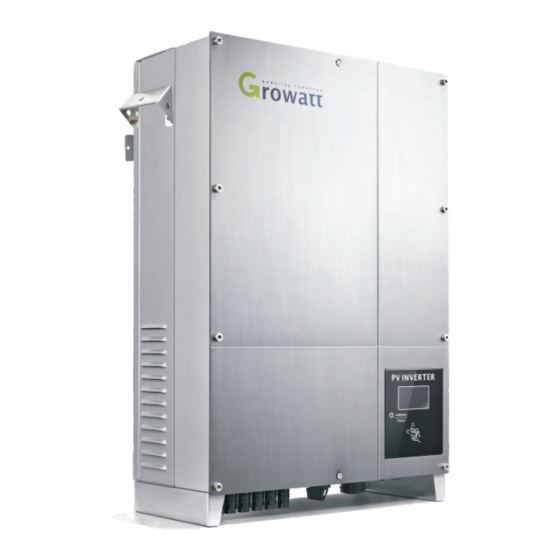
Growatt 7000UE
Growatt 8000UE
Growatt 9000UE
Growatt 10000UE
Growatt 12000UE
Growatt 18000UE
Growatt 20000UE
Advertisement


Need help?
Do you have a question about the UE Series and is the answer not in the manual?
Questions and answers
Growatt NEO 1000M - X installieren
Wie finde ich den Electrician Code